SlideShare a Scribd company logo
1 of 30
Download to read offline
Product: TRACK LOADER
Model: 977L TRACK LOADER 64X
Configuration: 977L TRACK-TYPE LOADER / POWER SHIFT / 64X00001-UP (MACHINE) POWERED BY 3306 ENGINE
Disassembly and Assembly
977L TRACK-TYPE TRACTOR POWER TRAIN
Media Number -SENR7794-00 Publication Date -01/09/1978 Date Updated -12/10/2001
Sprocket Assemblies
SMCS - 4164-11; 4164-12
Remove Sprocket Assemblies
start by:
a) remove track roller frame
1. Drain the oil from the final drive case.
1/12
977L TRACK-TYPE LOADER / POWER SHIFT / 64X00001-UP (MACHINE) POW...
2021/10/12
https://127.0.0.1/sisweb/sisweb/techdoc/techdoc_print_page.jsp?returnurl=/sis...
2. Remove guard (1), cap (2) and the gasket.
3. Remove lock (5), nut (4), washer assembly (3) and the shims from the sprocket shaft.
4. Remove bearing (6) and the seal from the holder assembly.
5. Remove bolt (8), the nut, lockwasher and lock (9) from holder assembly (7).
2/12
977L TRACK-TYPE LOADER / POWER SHIFT / 64X00001-UP (MACHINE) POW...
2021/10/12
https://127.0.0.1/sisweb/sisweb/techdoc/techdoc_print_page.jsp?returnurl=/sis...
6. Install washer assembly (3) and nut (4) on the sprocket shaft until there is a distance of
approximately .125 in. (3.175 mm) between washer assembly (3) and holder assembly (7). Make
sure the holes in washer assembly (3) are in alignment with the dowels in holder assembly (7).
7. Hit holder assembly (7) to loosen it from the taper on the sprocket shaft.
8. Fasten a hoist to holder assembly (7). Remove nut (4), washer assembly (3) and holder
assembly (7) and the adjustment nut as a unit. The weight of the unit is 80 lb. (36 kg).
9. Remove the outer half of Duo-Cone seal (10) from the adjustment nut.
10. Remove the inner half of Duo-Cone seal (10) from the sprocket.
NOTE: Keep the Duo-Cone seals for the sprocket and adjustment nut together so they will not be
mixed at assembly.
3/12
977L TRACK-TYPE LOADER / POWER SHIFT / 64X00001-UP (MACHINE) POW...
2021/10/12
https://127.0.0.1/sisweb/sisweb/techdoc/techdoc_print_page.jsp?returnurl=/sis...
11. Remove adjustment nut (11) from holder assembly (7).
12. Remove gasket (12) and seal (13) from hub assembly (7).
NOTE: Later machines do not have seal (13).
13. Remove cage (14) from holder assembly (7).
14. Remove bearing cup (15) from cage (14).
4/12
977L TRACK-TYPE LOADER / POWER SHIFT / 64X00001-UP (MACHINE) POW...
2021/10/12
https://127.0.0.1/sisweb/sisweb/techdoc/techdoc_print_page.jsp?returnurl=/sis...
15. Bend the tab of the lock from nut (16).
16. Use tool (A) to loosen nut (16) until it is free from the threads on the sprocket shaft. This will
push the bearing cone toward the end of the sprocket shaft.
17. Put tooling (B) in position and pull on nut (16) to remove the nut and bearing (17).
18. Remove the lock for nut (16) from the sprocket shaft.
19. Install nut (16) on the sprocket shaft until there is a clearance of .25 in. (6.35 mm) between the
nut and sprocket. Nut (16) is used for protection when the sprocket is loosened from the final drive
hub.
20. Remove key (18) from the sprocket shaft.
The sprocket is installed with a pressure of 45 to 50 tons (400 to 445
kN). Keep away from the area of the sprocket when it is loosened from
the hub with tooling (C).
5/12
977L TRACK-TYPE LOADER / POWER SHIFT / 64X00001-UP (MACHINE) POW...
2021/10/12
https://127.0.0.1/sisweb/sisweb/techdoc/techdoc_print_page.jsp?returnurl=/sis...
21. Install tooling (C) on the end of the sprocket shaft and sprocket (19) as shown.
22. Loosen the sprocket with tooling (C). Remove tooling (C) and nut (16).
23. Fasten a hoist to sprocket (19) and remove it from the final drive hub. The weight of the
sprocket is 400 lb. (180 kg).
24. Remove the outer half of Duo-Cone seal (20) from the sprocket.
25. Remove the inner half of Duo-Cone seal (20) from the final drive case. Keep the Duo-Cone
seals together so they will not be mixed at assembly.
Install Sprocket Assemblies
6/12
977L TRACK-TYPE LOADER / POWER SHIFT / 64X00001-UP (MACHINE) POW...
2021/10/12
https://127.0.0.1/sisweb/sisweb/techdoc/techdoc_print_page.jsp?returnurl=/sis...
1. Make sure the Duo-Cone seals for the final drive case and sprocket are clean and dry. Make
sure all metal surfaces that the seals make contact with are clean and dry. Install the Duo-Cone
seals in the final drive case and inner side of the sprocket with tool (A). Put a light amount of oil
on the metal surfaces of the seals that make contact with each other.
7/12
977L TRACK-TYPE LOADER / POWER SHIFT / 64X00001-UP (MACHINE) POW...
2021/10/12
https://127.0.0.1/sisweb/sisweb/techdoc/techdoc_print_page.jsp?returnurl=/sis...
2. Fasten a hoist to the sprocket (1) and put it in position on the final drive hub. Make sure the
splines of the sprocket and the hub are in alignment. Push the sprocket on the hub as far as
possible by hand.
NOTICE
Make sure the splines of the hub and sprocket are clean and dry.
3. Put tooling (B) in position to install sprocket (1) as follows:
a) Install the 1P5579 Adapter (2), spacer (3) and coupling (4) on the sprocket shaft as shown.
b) Put head (7) in position on cylinder group (9) and install the 6H4158 Pins (8). Install a ring on
each side of pins (8) to hold them.
c) Install 5P4183 Adapter (6) on the cylinder rod.
d) Put sleeve (5) in position as shown.
8/12
977L TRACK-TYPE LOADER / POWER SHIFT / 64X00001-UP (MACHINE) POW...
2021/10/12
https://127.0.0.1/sisweb/sisweb/techdoc/techdoc_print_page.jsp?returnurl=/sis...
e) Fasten a hoist to cylinder group (9) and put it in position. Install the 7M9772 Pin (10) to hold
the adapters together.
4. Install the sprocket with tooling (B) with a force of 45 to 50 tons (400 to 445 kN).
5. Remove tooling (B) from the sprocket shaft. Check the distance between the end of the splines
on the hub and the end of the sprocket with a depth micrometer. The distance must be .281 ± .060
in. (7.14 ± 1.52 mm).
6. Install the lock and nut (11) on the hub. Tighten the nut with tool (C).
7. Bend the tab of the lock over nut (11) to hold it in position.
8. Heat bearing (12) to a maximum temperature of 275° F (135° C). Install the bearing on the hub
and against the nut as shown.
9/12
977L TRACK-TYPE LOADER / POWER SHIFT / 64X00001-UP (MACHINE) POW...
2021/10/12
https://127.0.0.1/sisweb/sisweb/techdoc/techdoc_print_page.jsp?returnurl=/sis...
9. Lower the temperature of bearing cup (13). Install the bearing cup in cage (14) until it makes
contact with the bottom edge of the cage.
10. Put cage (14) in position in holder assembly (15) with the groove in the cage in alignment with
the dowel in the holder assembly.
11. Make sure the groove for the gasket in holder assembly (15) is clean and dry. Install a new
seal (17) and gasket (16) in holder assembly (15).
NOTE: Put liquid soap on seal (17) for easier installation. Later machines do not have seal (17).
12. Put a thin layer of 5P960 Multipurpose Type Grease on the threads and face of nut (18) that
makes contact with the gasket in the holder assembly. Install the nut on the holder.
10/12
977L TRACK-TYPE LOADER / POWER SHIFT / 64X00001-UP (MACHINE) PO...
2021/10/12
https://127.0.0.1/sisweb/sisweb/techdoc/techdoc_print_page.jsp?returnurl=/sis...
13. Install the outer half of the Duo-Cone seal in nut (18) with tool (A).
NOTE: The rubber seals and all of the surfaces that make contact with the rubber seals must be
clean and dry. Put clean SAE 30 oil on the contact surfaces of the metal seals.
14. Install the inner half of the Duo-Cone seal in the sprocket with tool (A).
15. Fasten a hoist to the holder assembly and put it in position on the sprocket shaft. Make sure the
groove in the holder assembly is in alignment with the key on the sprocket shaft.
16. Install lock (19), the bolt, lockwasher and nut for the holder assembly.
11/12
977L TRACK-TYPE LOADER / POWER SHIFT / 64X00001-UP (MACHINE) PO...
2021/10/12
https://127.0.0.1/sisweb/sisweb/techdoc/techdoc_print_page.jsp?returnurl=/sis...
17. Put 1P808 General Purpose Lubricant on the seal for bearing (20) and on the inside diameter
of bearing (20). Install the seal in bearing (20) and put the bearing in position.
18. Install shims (21) for the correct alignment of the sprocket and track roller frame. See
Alignment of Track Roller Frame in SPECIFICATIONS to find the correct amount of shims
needed.
19. Install washer assembly (22) and nut (23). Tighten the nut to a torque of 600 to 700 lb.ft. (810
to 950 N·m).
20. Install lock (24) to hold the nut in position.
21. Install guard (25), the gasket and cap (26) on the bearing.
22. Make an adjustment of the final drive bearings before the track roller frames are installed. See
Adjustment for Final Drive Bearings.
23. Fill the final drive case with oil to the correct level.
end by:
a) install track roller frames
12/12
977L TRACK-TYPE LOADER / POWER SHIFT / 64X00001-UP (MACHINE) PO...
2021/10/12
https://127.0.0.1/sisweb/sisweb/techdoc/techdoc_print_page.jsp?returnurl=/sis...
Product: TRACK LOADER
Model: 977L TRACK LOADER 64X
Configuration: 977L TRACK-TYPE LOADER / POWER SHIFT / 64X00001-UP (MACHINE) POWERED BY 3306 ENGINE
Disassembly and Assembly
977L TRACK-TYPE TRACTOR POWER TRAIN
Media Number -SENR7794-00 Publication Date -01/09/1978 Date Updated -12/10/2001
Adjustment For Final Drive Bearings
SMCS - 4164-11; 4164-12
Adjustment For Final Drive Bearings
1. Use tooling (A) to lift one side of the machine until the track is off the ground.
1/4
977L TRACK-TYPE LOADER / POWER SHIFT / 64X00001-UP (MACHINE) POW...
2021/10/12
https://127.0.0.1/sisweb/sisweb/techdoc/techdoc_print_page.jsp?returnurl=/sis...
2. Install tooling (B) and lower the weight of the machine on tooling (B).
3. Remove guards (1) and (2) from the track roller frame.
4. Remove cap (3) and the gasket from the bearing.
5. Remove bolt (4), the nut, lockwasher and lock (5) from the holder assembly.
6. Remove lock (7) and check the torque on nut (8). The nut must be tightened to a torque of 600
to 700 lb.ft. (810 to 950 N·m). Install lock (7).
7. Use tool (C) to loosen adjustment nut (6). Turn the nut in a clockwise direction to loosen it.
2/4
977L TRACK-TYPE LOADER / POWER SHIFT / 64X00001-UP (MACHINE) POW...
2021/10/12
https://127.0.0.1/sisweb/sisweb/techdoc/techdoc_print_page.jsp?returnurl=/sis...
8. Start the machine and turn the sprocket slowly while adjustment nut (6) is tightened with
tooling (D) to a torque of 2500 ± 300 lb.ft. (3380 ± 410 N·m). Tighten nut (6) in a
counterclockwise direction. On the left side of the machine the nut is tightened in a
counterclockwise direction also.
9. Turn adjustment nut (6) clockwise with tooling (D) (about six to ten lugs) to lower the torque to
less than 350 lb.ft. (470 N·m).
NOTE: If it is not possible to get a torque below 350 lb.ft. after the adjustment nut is loosened, a
separation of the tracks must be made to make the adjustment of the bearings.
10. Use tooling (D) to tighten adjustment nut (6) again to a torque of 350 ± 10 lb.ft. (470 ± 14
N·m).
11. Make a mark on nut (6) and the holder assembly. Tighten nut (6) in a counterclockwise
direction 6.36 ± .06 in. (161.5 ± 1.52 mm) of the circumference as measured on the holder
assembly outside diameter.
12. If necessary, tighten nut (6) more to install lock (5) in one of the notches of adjustment nut (6).
Install the bolt, nut and lockwasher to hold the lock in position.
13. Install the gasket and cap (3).
3/4
977L TRACK-TYPE LOADER / POWER SHIFT / 64X00001-UP (MACHINE) POW...
2021/10/12
https://127.0.0.1/sisweb/sisweb/techdoc/techdoc_print_page.jsp?returnurl=/sis...
14. Install guards (1) and (2) on the track roller frame.
15. Lift the machine with tooling (A) and remove tooling (B). Lower the machine to the ground
and remove tooling (A).
4/4
977L TRACK-TYPE LOADER / POWER SHIFT / 64X00001-UP (MACHINE) POW...
2021/10/12
https://127.0.0.1/sisweb/sisweb/techdoc/techdoc_print_page.jsp?returnurl=/sis...
Product: TRACK LOADER
Model: 977L TRACK LOADER 64X
Configuration: 977L TRACK-TYPE LOADER / POWER SHIFT / 64X00001-UP (MACHINE) POWERED BY 3306 ENGINE
Disassembly and Assembly
977L TRACK-TYPE TRACTOR POWER TRAIN
Media Number -SENR7794-00 Publication Date -01/09/1978 Date Updated -12/10/2001
Final Drive Cases, Gears, Idler Pinions And Bearings
SMCS - 4059; 4075-11; 4075-12
Remove Final Drive Cases, Gears, Idler Pinions And
Bearings
start by:
a) remove sprocket assemblies
1/9
977L TRACK-TYPE LOADER / POWER SHIFT / 64X00001-UP (MACHINE) POW...
2021/10/12
https://127.0.0.1/sisweb/sisweb/techdoc/techdoc_print_page.jsp?returnurl=/sis...
1. Remove the bolts that hold final drive case (1) in position.
2. Install three 1/2"-13 NC guide pins (3) through the final drive case and into the steering clutch
case. Install two 1/2"-13 NC forcing screws (2) in the final drive case. Tighten the screws evenly
until the case is approximately .25 in. (6.35 mm) away from the steering clutch case.
3. Install a piece of wire around two of the guide pins to hold the idler pinion in place.
NOTICE
The wire is to keep the planet carrier in position so it will not fall from
the steering clutch case when the final drive case is removed.
4. Tighten the forcing screws until tool (A) and a hoist can be fastened to final drive case (1).
Remove case (1) from the guide pins. The weight of the final drive case is 250 lb. (113 kg).
5. Remove the plugs from case (1) with tool group (B).
2/9
977L TRACK-TYPE LOADER / POWER SHIFT / 64X00001-UP (MACHINE) POW...
2021/10/12
https://127.0.0.1/sisweb/sisweb/techdoc/techdoc_print_page.jsp?returnurl=/sis...
6. Remove the dowels from case (1) with a 1/4"-20 NC bolt.
7. Use tooling (C) to remove race and roller assemblies (4) and (5) from the final drive case.
8. Fasten a hoist to the gear and hub (6). Remove the gear and hub from the sprocket shaft. The
weight of the gear and hub is 265 lb. (119 kg).
9. Put the gear and hub on wood blocks. Remove the bearing cone from the hub with tooling (D).
10. Remove the nuts from bolts (8). Use a hammer and soft punch to remove bolts (8) from gear
(7) and hub (6) as shown.
3/9
977L TRACK-TYPE LOADER / POWER SHIFT / 64X00001-UP (MACHINE) POW...
2021/10/12
https://127.0.0.1/sisweb/sisweb/techdoc/techdoc_print_page.jsp?returnurl=/sis...
11. Use a nylon strap and a pin or bolt with a length that is longer than the inside diameter of hub
(6) to fasten a hoist to the hub. Remove hub (6) from gear (7). The weight of the hub is 145 lb. (65
kg).
12. If necessary, remove bearing cup (9) from the steering clutch case.
13. Remove the wire from the gear and pinion. Fasten a hoist and remove gear (10) and the pinion
from the steering clutch case. The weight of the gear and pinion is 75 lb. (34 kg).
14. Put the gear and pinion on wood blocks. Use tooling (E) to remove the bearing races (11) from
each end of the pinion shaft.
15. Remove the pinion shaft from the gear as follows:
a) Put the gear and pinion shaft in a press as shown.
4/9
977L TRACK-TYPE LOADER / POWER SHIFT / 64X00001-UP (MACHINE) POW...
2021/10/12
https://127.0.0.1/sisweb/sisweb/techdoc/techdoc_print_page.jsp?returnurl=/sis...
TYPICAL EXAMPLE
b) Put a small amount of pressure on the pinion shaft with the press. Push the ring in the groove
on the pinion shaft with a hammer and punch. The ring will stay in the groove because of the
pressure on the pinion shaft.
c) When the ring is completely in the groove, the pinion shaft will slide out of the gear.
NOTICE
Too much pressure on the pinion shaft can cause damage to the gear.
16. If necessary, remove bearing race (12) with tooling (E).
17. Use three 1/2"-13 NC forcing screws to remove cage (13) from the steering clutch case.
5/9
977L TRACK-TYPE LOADER / POWER SHIFT / 64X00001-UP (MACHINE) POW...
2021/10/12
https://127.0.0.1/sisweb/sisweb/techdoc/techdoc_print_page.jsp?returnurl=/sis...
18. Use a 1/4"-20 NC bolt to remove the dowel from cage (13). Remove O-ring seal (14) from the
cage.
19. Use tooling (C) to remove the race and roller assembly from the cage.
Install Final Drive Cases, Gears, Idler Pinions And Bearings
1. Lower the temperature of roller and race assembly (1) and install it in cage (2). Make sure the
hole in the race and roller assembly is in alignment with the hole in cage (2) at assembly.
2. Put clean oil on O-ring seal (4) and install it on cage (2).
6/9
977L TRACK-TYPE LOADER / POWER SHIFT / 64X00001-UP (MACHINE) POW...
2021/10/12
https://127.0.0.1/sisweb/sisweb/techdoc/techdoc_print_page.jsp?returnurl=/sis...
3. Install dowel (3) to hold the race and roller assembly in cage (2).
4. Heat bearing race (5) to a maximum temperature of 275°F (135°C). Install bearing race (5) on
the pinion as shown.
5. Lower the temperature of bearing cup (6) and install it in the steering clutch case as shown.
6. Install the bearing and cage (2) in the steering clutch case. Make sure the oil groove next to the
bearing in the cage is at the bottom before the bolts are tightened.
7. If a separation of the idler gear and pinion was made, install a new retainer in the pinion. Install
the gear over the pinion so the deep chamfer is used to put the retainer under compression. Make
sure the retainer is engaged in the groove of the gear.
8. Heat bearing races (7) and (8) to a maximum temperature of 275°F (135°C) and install them on
the idler pinion.
9. Put 1P808 General Purpose Lubricant in the bearing to hold the rollers out for installation of
gear (9) and the pinion. Fasten a hoist to the gear and pinion. Install the gear (9) and pinion in the
steering clutch case.
10. Install three 1/2"-13 NC guide pins in the steering clutch case for installation of the final drive
case. Fasten a wire around the guide bolts, idler gear (9) and the pinion.
7/9
977L TRACK-TYPE LOADER / POWER SHIFT / 64X00001-UP (MACHINE) POW...
2021/10/12
https://127.0.0.1/sisweb/sisweb/techdoc/techdoc_print_page.jsp?returnurl=/sis...
NOTE: The wire will hold idler gear (9) and the pinion in position until the final drive case is
installed.
11. Fasten a hoist to hub (10) and put it in position in gear (11). Install the bolts, washers and nuts
that hold the hub and gear together.
12. Heat bearing cone (12) to a maximum temperature of 275° F (135° C). Install the bearing cone
on the hub as shown.
13. Fasten a hoist to hub (10) and the gear. Put hub (10) and the gear in position on the sprocket
shaft.
14. Lower the temperature of race and roller assemblies (14) and (15). Install the race and roller
assemblies in case (13). Make sure the hole in the race and roller assemblies are in alignment with
the dowel holes in case (13).
8/9
977L TRACK-TYPE LOADER / POWER SHIFT / 64X00001-UP (MACHINE) POW...
2021/10/12
https://127.0.0.1/sisweb/sisweb/techdoc/techdoc_print_page.jsp?returnurl=/sis...
15. Install dowel (16) and the plug in case (13) to hold race and roller assembly (15). Install the
dowel and plug to hold race and roller assembly (14). Put 1P808 General Purpose Lubricant in the
race and roller assemblies to hold the rollers out to prevent damage of parts when case (13) is
installed.
16. Fasten a hoist to case (13) with tool (A). Put 7M7260 Liquid Gasket Material on the machined
surface of the steering clutch case and case (13).
17. Put case (13) on the guide pins. Removo tool (A) and the wire used to hold the idler pinion.
Install the bolts and washers that hold case (13). Tighten the bolts to a torque of 100 ± 10 lb.ft.
(135 ± 14 N·m).
18. Fill the steering clutch case and final drive cases with oil to the correct level. See
LUBRICATION AND MAINTENANCE GUIDE.
end by:
a) install sprocket assemblies
9/9
977L TRACK-TYPE LOADER / POWER SHIFT / 64X00001-UP (MACHINE) POW...
2021/10/12
https://127.0.0.1/sisweb/sisweb/techdoc/techdoc_print_page.jsp?returnurl=/sis...
Product: TRACK LOADER
Model: 977L TRACK LOADER 64X
Configuration: 977L TRACK-TYPE LOADER / POWER SHIFT / 64X00001-UP (MACHINE) POWERED BY 3306 ENGINE
Disassembly and Assembly
977L TRACK-TYPE TRACTOR POWER TRAIN
Media Number -SENR7794-00 Publication Date -01/09/1978 Date Updated -12/10/2001
Sprocket Shafts
SMCS - 4058-11; 4058-12
Remove Sprocket Shafts
start by:
a) remove final drive cases, gears, idler pinions and bearings
1/5
977L TRACK-TYPE LOADER / POWER SHIFT / 64X00001-UP (MACHINE) POW...
2021/10/12
https://127.0.0.1/sisweb/sisweb/techdoc/techdoc_print_page.jsp?returnurl=/sis...
VIEW FROM UNDER MACHINE
1. Remove ring (2) and the pin from spanner nut (1).
2. Loosen nut (1) with tool (A) until there is a clearance of .125 in. (3.2 mm) between the nut and
the steering clutch case.
Do not remove nut (1) from the sprocket shaft threads until the shaft is
loosened with tooling (B). The nut will hold the shaft when it is loosened
from the taper in the steering clutch case.
3. Install tooling (B) to remove the sprocket shaft as follows:
a) Install the 5P4183 Adapter on the end of the sprocket shaft. Put the 5P4181 Adapter in the
5P4183 Adapter and install a 7M9772 Pin to hold the adapters together. Install a wire or 3P1770
Pin on each side of the pin to hold it in position.
b) Install the 7M9773 Adapter on the 5P4181 Adapter.
c) Connect the 9H3992 Head to the cylinder group with the 6H4158 Pins. Put a 7B2499 Ring on
each side of the pins to hold them.
d) Install the 7M9774 Coupling on the end of the cylinder group.
e) Fasten a hoist to the cylinder group and put it in position on the sleeve.
f) Install a 7M9772 Pin through the 7M9774 Coupling and 5P4181 Adapter. Put a wire or 3P1770
Pin on each side of the 7M9772 Pin to hold it.
4. Fasten a hoist to tooling (B) and loosen the sprocket shaft. Remove tooling (B). Remove nut (1)
from the sprocket shaft threads.
2/5
977L TRACK-TYPE LOADER / POWER SHIFT / 64X00001-UP (MACHINE) POW...
2021/10/12
https://127.0.0.1/sisweb/sisweb/techdoc/techdoc_print_page.jsp?returnurl=/sis...
5. Fasten a hoist to sprocket shaft (3) and remove it from the steering clutch case. The weight of
the sprocket shaft is 100 lb. (45 kg).
Install Sprocket Shafts
1. Fasten a hoist to sprocket shaft (1) and put it in the steering clutch case as far as possible by
hand.
2. Put the spanner nut on the end of the sprocket shaft under the steering clutch case.
3/5
977L TRACK-TYPE LOADER / POWER SHIFT / 64X00001-UP (MACHINE) POW...
2021/10/12
https://127.0.0.1/sisweb/sisweb/techdoc/techdoc_print_page.jsp?returnurl=/sis...
Suggest:
If the above button click is invalid.
Please download this document
first, and then click the above link
to download the complete manual.
Thank you so much for reading
3. Install tooling (A) on the end of the sprocket shaft. Use a hammer to push sprocket shaft (1)
until the spanner nut can be installed on the threads.
4. Install tooling (B) on the sprocket shaft as shown. Fasten a hoist to the tooling. Install the
sprocket shaft with tooling (B) with a force of 20 to 30 tons (180 to 265 kN).
5. Tighten the spanner nut with tool (C) while the pressure is still on the sprocket shaft. Tighten
the nut to a torque of 700 ± 50 lb.ft. (950 ± 70 N·m).
6. After the spanner nut is tightened, release the pressure on the sprocket shaft and remove tooling
(B).
7. Install holder assembly (2), the shims, washer assembly and nut on the sprocket shaft. Tighten
the nut to a torque of 600 to 700 lb.ft. (810 to 950 N·m).
8. Measure the distance from the face of the holder assembly to the steering clutch case. Distance
"X" must be 11.995 ± .062 in. (304.7 ± 1.57 mm) for a standard size sprocket shaft and 14.995
± .062 in. (380.9 ± 1.57 mm) for a Low Ground Pressure sprocket shaft.
9. To fasten nut (3) in position make a .368 in. (9.35 mm) hole in one of the grooves in nut (3).
Drill the hole through the nut and .75 in. (19.1 mm) deep in the sprocket shaft. Install pin (5) and
ring (4).
end by:
4/5
977L TRACK-TYPE LOADER / POWER SHIFT / 64X00001-UP (MACHINE) POW...
2021/10/12
https://127.0.0.1/sisweb/sisweb/techdoc/techdoc_print_page.jsp?returnurl=/sis...

More Related Content

Similar to Caterpillar Cat 977L TRACK LOADER (Prefix 64X) Service Repair Manual Instant Download.pdf

Caterpillar Cat 120H Motor Grader (Prefix 2AN) Service Repair Manual (2AN0000...
Caterpillar Cat 120H Motor Grader (Prefix 2AN) Service Repair Manual (2AN0000...Caterpillar Cat 120H Motor Grader (Prefix 2AN) Service Repair Manual (2AN0000...
Caterpillar Cat 120H Motor Grader (Prefix 2AN) Service Repair Manual (2AN0000...fujskkmdmdm
 
Caterpillar Cat 120H Motor Grader (Prefix 2AN) Service Repair Manual Instant ...
Caterpillar Cat 120H Motor Grader (Prefix 2AN) Service Repair Manual Instant ...Caterpillar Cat 120H Motor Grader (Prefix 2AN) Service Repair Manual Instant ...
Caterpillar Cat 120H Motor Grader (Prefix 2AN) Service Repair Manual Instant ...hean57759707
 
Caterpillar cat 120 h es motor grader (prefix 9yr) service repair manual (9yr...
Caterpillar cat 120 h es motor grader (prefix 9yr) service repair manual (9yr...Caterpillar cat 120 h es motor grader (prefix 9yr) service repair manual (9yr...
Caterpillar cat 120 h es motor grader (prefix 9yr) service repair manual (9yr...fjskekdmjekm
 
Caterpillar cat 120 h es motor grader (prefix 9yr) service repair manual (9yr...
Caterpillar cat 120 h es motor grader (prefix 9yr) service repair manual (9yr...Caterpillar cat 120 h es motor grader (prefix 9yr) service repair manual (9yr...
Caterpillar cat 120 h es motor grader (prefix 9yr) service repair manual (9yr...f9oseikkdks
 
Caterpillar cat 120 h es motor grader (prefix 6nm) service repair manual (6nm...
Caterpillar cat 120 h es motor grader (prefix 6nm) service repair manual (6nm...Caterpillar cat 120 h es motor grader (prefix 6nm) service repair manual (6nm...
Caterpillar cat 120 h es motor grader (prefix 6nm) service repair manual (6nm...dkdmidkkdk
 
Caterpillar cat 120 h es motor grader (prefix 6nm) service repair manual (6nm...
Caterpillar cat 120 h es motor grader (prefix 6nm) service repair manual (6nm...Caterpillar cat 120 h es motor grader (prefix 6nm) service repair manual (6nm...
Caterpillar cat 120 h es motor grader (prefix 6nm) service repair manual (6nm...fjjsekkdmme
 
Caterpillar cat 120 h es motor grader (prefix 6nm) service repair manual (6nm...
Caterpillar cat 120 h es motor grader (prefix 6nm) service repair manual (6nm...Caterpillar cat 120 h es motor grader (prefix 6nm) service repair manual (6nm...
Caterpillar cat 120 h es motor grader (prefix 6nm) service repair manual (6nm...fjsekdmmeed
 

Similar to Caterpillar Cat 977L TRACK LOADER (Prefix 64X) Service Repair Manual Instant Download.pdf (7)

Caterpillar Cat 120H Motor Grader (Prefix 2AN) Service Repair Manual (2AN0000...
Caterpillar Cat 120H Motor Grader (Prefix 2AN) Service Repair Manual (2AN0000...Caterpillar Cat 120H Motor Grader (Prefix 2AN) Service Repair Manual (2AN0000...
Caterpillar Cat 120H Motor Grader (Prefix 2AN) Service Repair Manual (2AN0000...
 
Caterpillar Cat 120H Motor Grader (Prefix 2AN) Service Repair Manual Instant ...
Caterpillar Cat 120H Motor Grader (Prefix 2AN) Service Repair Manual Instant ...Caterpillar Cat 120H Motor Grader (Prefix 2AN) Service Repair Manual Instant ...
Caterpillar Cat 120H Motor Grader (Prefix 2AN) Service Repair Manual Instant ...
 
Caterpillar cat 120 h es motor grader (prefix 9yr) service repair manual (9yr...
Caterpillar cat 120 h es motor grader (prefix 9yr) service repair manual (9yr...Caterpillar cat 120 h es motor grader (prefix 9yr) service repair manual (9yr...
Caterpillar cat 120 h es motor grader (prefix 9yr) service repair manual (9yr...
 
Caterpillar cat 120 h es motor grader (prefix 9yr) service repair manual (9yr...
Caterpillar cat 120 h es motor grader (prefix 9yr) service repair manual (9yr...Caterpillar cat 120 h es motor grader (prefix 9yr) service repair manual (9yr...
Caterpillar cat 120 h es motor grader (prefix 9yr) service repair manual (9yr...
 
Caterpillar cat 120 h es motor grader (prefix 6nm) service repair manual (6nm...
Caterpillar cat 120 h es motor grader (prefix 6nm) service repair manual (6nm...Caterpillar cat 120 h es motor grader (prefix 6nm) service repair manual (6nm...
Caterpillar cat 120 h es motor grader (prefix 6nm) service repair manual (6nm...
 
Caterpillar cat 120 h es motor grader (prefix 6nm) service repair manual (6nm...
Caterpillar cat 120 h es motor grader (prefix 6nm) service repair manual (6nm...Caterpillar cat 120 h es motor grader (prefix 6nm) service repair manual (6nm...
Caterpillar cat 120 h es motor grader (prefix 6nm) service repair manual (6nm...
 

More from fujskekkdm8ik

Caterpillar Cat D6T XL TRACK-TYPE TRACTOR (Prefix KMR) Service Repair Manual ...
Caterpillar Cat D6T XL TRACK-TYPE TRACTOR (Prefix KMR) Service Repair Manual ...Caterpillar Cat D6T XL TRACK-TYPE TRACTOR (Prefix KMR) Service Repair Manual ...
Caterpillar Cat D6T XL TRACK-TYPE TRACTOR (Prefix KMR) Service Repair Manual ...fujskekkdm8ik
 
Caterpillar Cat D6T TRACK-TYPE TRACTOR (Prefix SMC) Service Repair Manual Ins...
Caterpillar Cat D6T TRACK-TYPE TRACTOR (Prefix SMC) Service Repair Manual Ins...Caterpillar Cat D6T TRACK-TYPE TRACTOR (Prefix SMC) Service Repair Manual Ins...
Caterpillar Cat D6T TRACK-TYPE TRACTOR (Prefix SMC) Service Repair Manual Ins...fujskekkdm8ik
 
Caterpillar Cat D7G2 TRACK-TYPE TRACTOR (Prefix C7G) Service Repair Manual In...
Caterpillar Cat D7G2 TRACK-TYPE TRACTOR (Prefix C7G) Service Repair Manual In...Caterpillar Cat D7G2 TRACK-TYPE TRACTOR (Prefix C7G) Service Repair Manual In...
Caterpillar Cat D7G2 TRACK-TYPE TRACTOR (Prefix C7G) Service Repair Manual In...fujskekkdm8ik
 
Caterpillar Cat 311F LRR Excavator (Prefix LZF) Service Repair Manual Instant...
Caterpillar Cat 311F LRR Excavator (Prefix LZF) Service Repair Manual Instant...Caterpillar Cat 311F LRR Excavator (Prefix LZF) Service Repair Manual Instant...
Caterpillar Cat 311F LRR Excavator (Prefix LZF) Service Repair Manual Instant...fujskekkdm8ik
 
Caterpillar Cat 120 MOTOR GRADER (Prefix 10R) Service Repair Manual Instant D...
Caterpillar Cat 120 MOTOR GRADER (Prefix 10R) Service Repair Manual Instant D...Caterpillar Cat 120 MOTOR GRADER (Prefix 10R) Service Repair Manual Instant D...
Caterpillar Cat 120 MOTOR GRADER (Prefix 10R) Service Repair Manual Instant D...fujskekkdm8ik
 
Caterpillar Cat 340 Excavator (Prefix TYH) Service Repair Manual Instant Down...
Caterpillar Cat 340 Excavator (Prefix TYH) Service Repair Manual Instant Down...Caterpillar Cat 340 Excavator (Prefix TYH) Service Repair Manual Instant Down...
Caterpillar Cat 340 Excavator (Prefix TYH) Service Repair Manual Instant Down...fujskekkdm8ik
 
Caterpillar Cat 215B EXCAVATOR (Prefix 2XC) Service Repair Manual Instant Dow...
Caterpillar Cat 215B EXCAVATOR (Prefix 2XC) Service Repair Manual Instant Dow...Caterpillar Cat 215B EXCAVATOR (Prefix 2XC) Service Repair Manual Instant Dow...
Caterpillar Cat 215B EXCAVATOR (Prefix 2XC) Service Repair Manual Instant Dow...fujskekkdm8ik
 
Caterpillar Cat 120 MOTOR GRADER (Prefix 10R) Service Repair Manual Instant D...
Caterpillar Cat 120 MOTOR GRADER (Prefix 10R) Service Repair Manual Instant D...Caterpillar Cat 120 MOTOR GRADER (Prefix 10R) Service Repair Manual Instant D...
Caterpillar Cat 120 MOTOR GRADER (Prefix 10R) Service Repair Manual Instant D...fujskekkdm8ik
 
Caterpillar Cat 231D EXCAVATOR (Prefix 1NK) Service Repair Manual Instant Dow...
Caterpillar Cat 231D EXCAVATOR (Prefix 1NK) Service Repair Manual Instant Dow...Caterpillar Cat 231D EXCAVATOR (Prefix 1NK) Service Repair Manual Instant Dow...
Caterpillar Cat 231D EXCAVATOR (Prefix 1NK) Service Repair Manual Instant Dow...fujskekkdm8ik
 
Caterpillar Cat 12H Motor Grader (Prefix AMZ) Service Repair Manual Instant D...
Caterpillar Cat 12H Motor Grader (Prefix AMZ) Service Repair Manual Instant D...Caterpillar Cat 12H Motor Grader (Prefix AMZ) Service Repair Manual Instant D...
Caterpillar Cat 12H Motor Grader (Prefix AMZ) Service Repair Manual Instant D...fujskekkdm8ik
 
Caterpillar Cat D6R III TRACK-TYPE TRACTOR (Prefix GMT) Service Repair Manual...
Caterpillar Cat D6R III TRACK-TYPE TRACTOR (Prefix GMT) Service Repair Manual...Caterpillar Cat D6R III TRACK-TYPE TRACTOR (Prefix GMT) Service Repair Manual...
Caterpillar Cat D6R III TRACK-TYPE TRACTOR (Prefix GMT) Service Repair Manual...fujskekkdm8ik
 
Caterpillar Cat D6T TRACK-TYPE TRACTOR (Prefix HYT) Service Repair Manual Ins...
Caterpillar Cat D6T TRACK-TYPE TRACTOR (Prefix HYT) Service Repair Manual Ins...Caterpillar Cat D6T TRACK-TYPE TRACTOR (Prefix HYT) Service Repair Manual Ins...
Caterpillar Cat D6T TRACK-TYPE TRACTOR (Prefix HYT) Service Repair Manual Ins...fujskekkdm8ik
 
Caterpillar Cat D6H XL TRACK-TYPE TRACTOR (Prefix 8KK) Service Repair Manual ...
Caterpillar Cat D6H XL TRACK-TYPE TRACTOR (Prefix 8KK) Service Repair Manual ...Caterpillar Cat D6H XL TRACK-TYPE TRACTOR (Prefix 8KK) Service Repair Manual ...
Caterpillar Cat D6H XL TRACK-TYPE TRACTOR (Prefix 8KK) Service Repair Manual ...fujskekkdm8ik
 
Caterpillar Cat D6H TRACK-TYPE TRACTOR (Prefix 4GG) Service Repair Manual Ins...
Caterpillar Cat D6H TRACK-TYPE TRACTOR (Prefix 4GG) Service Repair Manual Ins...Caterpillar Cat D6H TRACK-TYPE TRACTOR (Prefix 4GG) Service Repair Manual Ins...
Caterpillar Cat D6H TRACK-TYPE TRACTOR (Prefix 4GG) Service Repair Manual Ins...fujskekkdm8ik
 
Caterpillar Cat CB-534D, CB-534DXW Vibratory Compactor (Prefix GCA) Service R...
Caterpillar Cat CB-534D, CB-534DXW Vibratory Compactor (Prefix GCA) Service R...Caterpillar Cat CB-534D, CB-534DXW Vibratory Compactor (Prefix GCA) Service R...
Caterpillar Cat CB-534D, CB-534DXW Vibratory Compactor (Prefix GCA) Service R...fujskekkdm8ik
 
Caterpillar Cat 990H Wheel Loader (Prefix BWX) Service Repair Manual Instant ...
Caterpillar Cat 990H Wheel Loader (Prefix BWX) Service Repair Manual Instant ...Caterpillar Cat 990H Wheel Loader (Prefix BWX) Service Repair Manual Instant ...
Caterpillar Cat 990H Wheel Loader (Prefix BWX) Service Repair Manual Instant ...fujskekkdm8ik
 
Caterpillar Cat 966M Wheel Loader (Prefix R8D) Service Repair Manual Instant ...
Caterpillar Cat 966M Wheel Loader (Prefix R8D) Service Repair Manual Instant ...Caterpillar Cat 966M Wheel Loader (Prefix R8D) Service Repair Manual Instant ...
Caterpillar Cat 966M Wheel Loader (Prefix R8D) Service Repair Manual Instant ...fujskekkdm8ik
 
Caterpillar Cat 992C Wheel Loader (Prefix 49Z) Service Repair Manual Instant ...
Caterpillar Cat 992C Wheel Loader (Prefix 49Z) Service Repair Manual Instant ...Caterpillar Cat 992C Wheel Loader (Prefix 49Z) Service Repair Manual Instant ...
Caterpillar Cat 992C Wheel Loader (Prefix 49Z) Service Repair Manual Instant ...fujskekkdm8ik
 

More from fujskekkdm8ik (18)

Caterpillar Cat D6T XL TRACK-TYPE TRACTOR (Prefix KMR) Service Repair Manual ...
Caterpillar Cat D6T XL TRACK-TYPE TRACTOR (Prefix KMR) Service Repair Manual ...Caterpillar Cat D6T XL TRACK-TYPE TRACTOR (Prefix KMR) Service Repair Manual ...
Caterpillar Cat D6T XL TRACK-TYPE TRACTOR (Prefix KMR) Service Repair Manual ...
 
Caterpillar Cat D6T TRACK-TYPE TRACTOR (Prefix SMC) Service Repair Manual Ins...
Caterpillar Cat D6T TRACK-TYPE TRACTOR (Prefix SMC) Service Repair Manual Ins...Caterpillar Cat D6T TRACK-TYPE TRACTOR (Prefix SMC) Service Repair Manual Ins...
Caterpillar Cat D6T TRACK-TYPE TRACTOR (Prefix SMC) Service Repair Manual Ins...
 
Caterpillar Cat D7G2 TRACK-TYPE TRACTOR (Prefix C7G) Service Repair Manual In...
Caterpillar Cat D7G2 TRACK-TYPE TRACTOR (Prefix C7G) Service Repair Manual In...Caterpillar Cat D7G2 TRACK-TYPE TRACTOR (Prefix C7G) Service Repair Manual In...
Caterpillar Cat D7G2 TRACK-TYPE TRACTOR (Prefix C7G) Service Repair Manual In...
 
Caterpillar Cat 311F LRR Excavator (Prefix LZF) Service Repair Manual Instant...
Caterpillar Cat 311F LRR Excavator (Prefix LZF) Service Repair Manual Instant...Caterpillar Cat 311F LRR Excavator (Prefix LZF) Service Repair Manual Instant...
Caterpillar Cat 311F LRR Excavator (Prefix LZF) Service Repair Manual Instant...
 
Caterpillar Cat 120 MOTOR GRADER (Prefix 10R) Service Repair Manual Instant D...
Caterpillar Cat 120 MOTOR GRADER (Prefix 10R) Service Repair Manual Instant D...Caterpillar Cat 120 MOTOR GRADER (Prefix 10R) Service Repair Manual Instant D...
Caterpillar Cat 120 MOTOR GRADER (Prefix 10R) Service Repair Manual Instant D...
 
Caterpillar Cat 340 Excavator (Prefix TYH) Service Repair Manual Instant Down...
Caterpillar Cat 340 Excavator (Prefix TYH) Service Repair Manual Instant Down...Caterpillar Cat 340 Excavator (Prefix TYH) Service Repair Manual Instant Down...
Caterpillar Cat 340 Excavator (Prefix TYH) Service Repair Manual Instant Down...
 
Caterpillar Cat 215B EXCAVATOR (Prefix 2XC) Service Repair Manual Instant Dow...
Caterpillar Cat 215B EXCAVATOR (Prefix 2XC) Service Repair Manual Instant Dow...Caterpillar Cat 215B EXCAVATOR (Prefix 2XC) Service Repair Manual Instant Dow...
Caterpillar Cat 215B EXCAVATOR (Prefix 2XC) Service Repair Manual Instant Dow...
 
Caterpillar Cat 120 MOTOR GRADER (Prefix 10R) Service Repair Manual Instant D...
Caterpillar Cat 120 MOTOR GRADER (Prefix 10R) Service Repair Manual Instant D...Caterpillar Cat 120 MOTOR GRADER (Prefix 10R) Service Repair Manual Instant D...
Caterpillar Cat 120 MOTOR GRADER (Prefix 10R) Service Repair Manual Instant D...
 
Caterpillar Cat 231D EXCAVATOR (Prefix 1NK) Service Repair Manual Instant Dow...
Caterpillar Cat 231D EXCAVATOR (Prefix 1NK) Service Repair Manual Instant Dow...Caterpillar Cat 231D EXCAVATOR (Prefix 1NK) Service Repair Manual Instant Dow...
Caterpillar Cat 231D EXCAVATOR (Prefix 1NK) Service Repair Manual Instant Dow...
 
Caterpillar Cat 12H Motor Grader (Prefix AMZ) Service Repair Manual Instant D...
Caterpillar Cat 12H Motor Grader (Prefix AMZ) Service Repair Manual Instant D...Caterpillar Cat 12H Motor Grader (Prefix AMZ) Service Repair Manual Instant D...
Caterpillar Cat 12H Motor Grader (Prefix AMZ) Service Repair Manual Instant D...
 
Caterpillar Cat D6R III TRACK-TYPE TRACTOR (Prefix GMT) Service Repair Manual...
Caterpillar Cat D6R III TRACK-TYPE TRACTOR (Prefix GMT) Service Repair Manual...Caterpillar Cat D6R III TRACK-TYPE TRACTOR (Prefix GMT) Service Repair Manual...
Caterpillar Cat D6R III TRACK-TYPE TRACTOR (Prefix GMT) Service Repair Manual...
 
Caterpillar Cat D6T TRACK-TYPE TRACTOR (Prefix HYT) Service Repair Manual Ins...
Caterpillar Cat D6T TRACK-TYPE TRACTOR (Prefix HYT) Service Repair Manual Ins...Caterpillar Cat D6T TRACK-TYPE TRACTOR (Prefix HYT) Service Repair Manual Ins...
Caterpillar Cat D6T TRACK-TYPE TRACTOR (Prefix HYT) Service Repair Manual Ins...
 
Caterpillar Cat D6H XL TRACK-TYPE TRACTOR (Prefix 8KK) Service Repair Manual ...
Caterpillar Cat D6H XL TRACK-TYPE TRACTOR (Prefix 8KK) Service Repair Manual ...Caterpillar Cat D6H XL TRACK-TYPE TRACTOR (Prefix 8KK) Service Repair Manual ...
Caterpillar Cat D6H XL TRACK-TYPE TRACTOR (Prefix 8KK) Service Repair Manual ...
 
Caterpillar Cat D6H TRACK-TYPE TRACTOR (Prefix 4GG) Service Repair Manual Ins...
Caterpillar Cat D6H TRACK-TYPE TRACTOR (Prefix 4GG) Service Repair Manual Ins...Caterpillar Cat D6H TRACK-TYPE TRACTOR (Prefix 4GG) Service Repair Manual Ins...
Caterpillar Cat D6H TRACK-TYPE TRACTOR (Prefix 4GG) Service Repair Manual Ins...
 
Caterpillar Cat CB-534D, CB-534DXW Vibratory Compactor (Prefix GCA) Service R...
Caterpillar Cat CB-534D, CB-534DXW Vibratory Compactor (Prefix GCA) Service R...Caterpillar Cat CB-534D, CB-534DXW Vibratory Compactor (Prefix GCA) Service R...
Caterpillar Cat CB-534D, CB-534DXW Vibratory Compactor (Prefix GCA) Service R...
 
Caterpillar Cat 990H Wheel Loader (Prefix BWX) Service Repair Manual Instant ...
Caterpillar Cat 990H Wheel Loader (Prefix BWX) Service Repair Manual Instant ...Caterpillar Cat 990H Wheel Loader (Prefix BWX) Service Repair Manual Instant ...
Caterpillar Cat 990H Wheel Loader (Prefix BWX) Service Repair Manual Instant ...
 
Caterpillar Cat 966M Wheel Loader (Prefix R8D) Service Repair Manual Instant ...
Caterpillar Cat 966M Wheel Loader (Prefix R8D) Service Repair Manual Instant ...Caterpillar Cat 966M Wheel Loader (Prefix R8D) Service Repair Manual Instant ...
Caterpillar Cat 966M Wheel Loader (Prefix R8D) Service Repair Manual Instant ...
 
Caterpillar Cat 992C Wheel Loader (Prefix 49Z) Service Repair Manual Instant ...
Caterpillar Cat 992C Wheel Loader (Prefix 49Z) Service Repair Manual Instant ...Caterpillar Cat 992C Wheel Loader (Prefix 49Z) Service Repair Manual Instant ...
Caterpillar Cat 992C Wheel Loader (Prefix 49Z) Service Repair Manual Instant ...
 

Recently uploaded

Somya Surve Escorts Service Bilaspur ❣️ 7014168258 ❣️ High Cost Unlimited Har...
Somya Surve Escorts Service Bilaspur ❣️ 7014168258 ❣️ High Cost Unlimited Har...Somya Surve Escorts Service Bilaspur ❣️ 7014168258 ❣️ High Cost Unlimited Har...
Somya Surve Escorts Service Bilaspur ❣️ 7014168258 ❣️ High Cost Unlimited Har...nirzagarg
 
Top Rated Call Girls Mumbai Central : 9920725232 We offer Beautiful and sexy ...
Top Rated Call Girls Mumbai Central : 9920725232 We offer Beautiful and sexy ...Top Rated Call Girls Mumbai Central : 9920725232 We offer Beautiful and sexy ...
Top Rated Call Girls Mumbai Central : 9920725232 We offer Beautiful and sexy ...amitlee9823
 
Vip Mumbai Call Girls Mumbai Call On 9920725232 With Body to body massage wit...
Vip Mumbai Call Girls Mumbai Call On 9920725232 With Body to body massage wit...Vip Mumbai Call Girls Mumbai Call On 9920725232 With Body to body massage wit...
Vip Mumbai Call Girls Mumbai Call On 9920725232 With Body to body massage wit...amitlee9823
 
Is Your BMW PDC Malfunctioning Discover How to Easily Reset It
Is Your BMW PDC Malfunctioning Discover How to Easily Reset ItIs Your BMW PDC Malfunctioning Discover How to Easily Reset It
Is Your BMW PDC Malfunctioning Discover How to Easily Reset ItEuroService Automotive
 
➥🔝 7737669865 🔝▻ Asansol Call-girls in Women Seeking Men 🔝Asansol🔝 Escorts...
➥🔝 7737669865 🔝▻ Asansol Call-girls in Women Seeking Men  🔝Asansol🔝   Escorts...➥🔝 7737669865 🔝▻ Asansol Call-girls in Women Seeking Men  🔝Asansol🔝   Escorts...
➥🔝 7737669865 🔝▻ Asansol Call-girls in Women Seeking Men 🔝Asansol🔝 Escorts...amitlee9823
 
一比一原版(PU学位证书)普渡大学毕业证学历认证加急办理
一比一原版(PU学位证书)普渡大学毕业证学历认证加急办理一比一原版(PU学位证书)普渡大学毕业证学历认证加急办理
一比一原版(PU学位证书)普渡大学毕业证学历认证加急办理ezgenuh
 
Call Girls in Malviya Nagar Delhi 💯 Call Us 🔝9205541914 🔝( Delhi) Escorts Ser...
Call Girls in Malviya Nagar Delhi 💯 Call Us 🔝9205541914 🔝( Delhi) Escorts Ser...Call Girls in Malviya Nagar Delhi 💯 Call Us 🔝9205541914 🔝( Delhi) Escorts Ser...
Call Girls in Malviya Nagar Delhi 💯 Call Us 🔝9205541914 🔝( Delhi) Escorts Ser...Delhi Call girls
 
Is Your Volvo XC90 Displaying Anti-Skid Service Required Alert Here's Why
Is Your Volvo XC90 Displaying Anti-Skid Service Required Alert Here's WhyIs Your Volvo XC90 Displaying Anti-Skid Service Required Alert Here's Why
Is Your Volvo XC90 Displaying Anti-Skid Service Required Alert Here's WhyBavarium Autoworks
 
Sanjay Nagar Call Girls: 🍓 7737669865 🍓 High Profile Model Escorts | Bangalor...
Sanjay Nagar Call Girls: 🍓 7737669865 🍓 High Profile Model Escorts | Bangalor...Sanjay Nagar Call Girls: 🍓 7737669865 🍓 High Profile Model Escorts | Bangalor...
Sanjay Nagar Call Girls: 🍓 7737669865 🍓 High Profile Model Escorts | Bangalor...amitlee9823
 
FULL NIGHT — 9999894380 Call Girls In Jagat Puri | Delhi
FULL NIGHT — 9999894380 Call Girls In Jagat Puri | DelhiFULL NIGHT — 9999894380 Call Girls In Jagat Puri | Delhi
FULL NIGHT — 9999894380 Call Girls In Jagat Puri | DelhiSaketCallGirlsCallUs
 
Top Rated Call Girls South Mumbai : 9920725232 We offer Beautiful and sexy Ca...
Top Rated Call Girls South Mumbai : 9920725232 We offer Beautiful and sexy Ca...Top Rated Call Girls South Mumbai : 9920725232 We offer Beautiful and sexy Ca...
Top Rated Call Girls South Mumbai : 9920725232 We offer Beautiful and sexy Ca...amitlee9823
 
ELECTRICITÉ TMT 55.pdf electrick diagram manitout
ELECTRICITÉ TMT 55.pdf electrick diagram manitoutELECTRICITÉ TMT 55.pdf electrick diagram manitout
ELECTRICITÉ TMT 55.pdf electrick diagram manitoutssjews46
 
Vip Mumbai Call Girls Colaba Call On 9920725232 With Body to body massage wit...
Vip Mumbai Call Girls Colaba Call On 9920725232 With Body to body massage wit...Vip Mumbai Call Girls Colaba Call On 9920725232 With Body to body massage wit...
Vip Mumbai Call Girls Colaba Call On 9920725232 With Body to body massage wit...amitlee9823
 
Call Girls in Malviya Nagar Delhi 💯 Call Us 🔝9205541914 🔝( Delhi) Escorts Ser...
Call Girls in Malviya Nagar Delhi 💯 Call Us 🔝9205541914 🔝( Delhi) Escorts Ser...Call Girls in Malviya Nagar Delhi 💯 Call Us 🔝9205541914 🔝( Delhi) Escorts Ser...
Call Girls in Malviya Nagar Delhi 💯 Call Us 🔝9205541914 🔝( Delhi) Escorts Ser...Delhi Call girls
 
What Does The Engine Malfunction Reduced Power Message Mean For Your BMW X5
What Does The Engine Malfunction Reduced Power Message Mean For Your BMW X5What Does The Engine Malfunction Reduced Power Message Mean For Your BMW X5
What Does The Engine Malfunction Reduced Power Message Mean For Your BMW X5Bavarian Workshop
 
+971565801893>>SAFE AND ORIGINAL ABORTION PILLS FOR SALE IN ABUDHABI,DUBAI MA...
+971565801893>>SAFE AND ORIGINAL ABORTION PILLS FOR SALE IN ABUDHABI,DUBAI MA...+971565801893>>SAFE AND ORIGINAL ABORTION PILLS FOR SALE IN ABUDHABI,DUBAI MA...
+971565801893>>SAFE AND ORIGINAL ABORTION PILLS FOR SALE IN ABUDHABI,DUBAI MA...Health
 
Why Does My Porsche Cayenne's Exhaust Sound So Loud
Why Does My Porsche Cayenne's Exhaust Sound So LoudWhy Does My Porsche Cayenne's Exhaust Sound So Loud
Why Does My Porsche Cayenne's Exhaust Sound So LoudRoyalty Auto Service
 

Recently uploaded (20)

Somya Surve Escorts Service Bilaspur ❣️ 7014168258 ❣️ High Cost Unlimited Har...
Somya Surve Escorts Service Bilaspur ❣️ 7014168258 ❣️ High Cost Unlimited Har...Somya Surve Escorts Service Bilaspur ❣️ 7014168258 ❣️ High Cost Unlimited Har...
Somya Surve Escorts Service Bilaspur ❣️ 7014168258 ❣️ High Cost Unlimited Har...
 
Stay Cool and Compliant: Know Your Window Tint Laws Before You Tint
Stay Cool and Compliant: Know Your Window Tint Laws Before You TintStay Cool and Compliant: Know Your Window Tint Laws Before You Tint
Stay Cool and Compliant: Know Your Window Tint Laws Before You Tint
 
Top Rated Call Girls Mumbai Central : 9920725232 We offer Beautiful and sexy ...
Top Rated Call Girls Mumbai Central : 9920725232 We offer Beautiful and sexy ...Top Rated Call Girls Mumbai Central : 9920725232 We offer Beautiful and sexy ...
Top Rated Call Girls Mumbai Central : 9920725232 We offer Beautiful and sexy ...
 
Vip Mumbai Call Girls Mumbai Call On 9920725232 With Body to body massage wit...
Vip Mumbai Call Girls Mumbai Call On 9920725232 With Body to body massage wit...Vip Mumbai Call Girls Mumbai Call On 9920725232 With Body to body massage wit...
Vip Mumbai Call Girls Mumbai Call On 9920725232 With Body to body massage wit...
 
Is Your BMW PDC Malfunctioning Discover How to Easily Reset It
Is Your BMW PDC Malfunctioning Discover How to Easily Reset ItIs Your BMW PDC Malfunctioning Discover How to Easily Reset It
Is Your BMW PDC Malfunctioning Discover How to Easily Reset It
 
➥🔝 7737669865 🔝▻ Asansol Call-girls in Women Seeking Men 🔝Asansol🔝 Escorts...
➥🔝 7737669865 🔝▻ Asansol Call-girls in Women Seeking Men  🔝Asansol🔝   Escorts...➥🔝 7737669865 🔝▻ Asansol Call-girls in Women Seeking Men  🔝Asansol🔝   Escorts...
➥🔝 7737669865 🔝▻ Asansol Call-girls in Women Seeking Men 🔝Asansol🔝 Escorts...
 
Call Girls in Patel Nagar, Delhi 💯 Call Us 🔝9953056974 🔝 Escort Service
Call Girls in Patel Nagar, Delhi 💯 Call Us 🔝9953056974 🔝 Escort ServiceCall Girls in Patel Nagar, Delhi 💯 Call Us 🔝9953056974 🔝 Escort Service
Call Girls in Patel Nagar, Delhi 💯 Call Us 🔝9953056974 🔝 Escort Service
 
一比一原版(PU学位证书)普渡大学毕业证学历认证加急办理
一比一原版(PU学位证书)普渡大学毕业证学历认证加急办理一比一原版(PU学位证书)普渡大学毕业证学历认证加急办理
一比一原版(PU学位证书)普渡大学毕业证学历认证加急办理
 
Call Girls in Malviya Nagar Delhi 💯 Call Us 🔝9205541914 🔝( Delhi) Escorts Ser...
Call Girls in Malviya Nagar Delhi 💯 Call Us 🔝9205541914 🔝( Delhi) Escorts Ser...Call Girls in Malviya Nagar Delhi 💯 Call Us 🔝9205541914 🔝( Delhi) Escorts Ser...
Call Girls in Malviya Nagar Delhi 💯 Call Us 🔝9205541914 🔝( Delhi) Escorts Ser...
 
Is Your Volvo XC90 Displaying Anti-Skid Service Required Alert Here's Why
Is Your Volvo XC90 Displaying Anti-Skid Service Required Alert Here's WhyIs Your Volvo XC90 Displaying Anti-Skid Service Required Alert Here's Why
Is Your Volvo XC90 Displaying Anti-Skid Service Required Alert Here's Why
 
Sanjay Nagar Call Girls: 🍓 7737669865 🍓 High Profile Model Escorts | Bangalor...
Sanjay Nagar Call Girls: 🍓 7737669865 🍓 High Profile Model Escorts | Bangalor...Sanjay Nagar Call Girls: 🍓 7737669865 🍓 High Profile Model Escorts | Bangalor...
Sanjay Nagar Call Girls: 🍓 7737669865 🍓 High Profile Model Escorts | Bangalor...
 
FULL NIGHT — 9999894380 Call Girls In Jagat Puri | Delhi
FULL NIGHT — 9999894380 Call Girls In Jagat Puri | DelhiFULL NIGHT — 9999894380 Call Girls In Jagat Puri | Delhi
FULL NIGHT — 9999894380 Call Girls In Jagat Puri | Delhi
 
Top Rated Call Girls South Mumbai : 9920725232 We offer Beautiful and sexy Ca...
Top Rated Call Girls South Mumbai : 9920725232 We offer Beautiful and sexy Ca...Top Rated Call Girls South Mumbai : 9920725232 We offer Beautiful and sexy Ca...
Top Rated Call Girls South Mumbai : 9920725232 We offer Beautiful and sexy Ca...
 
ELECTRICITÉ TMT 55.pdf electrick diagram manitout
ELECTRICITÉ TMT 55.pdf electrick diagram manitoutELECTRICITÉ TMT 55.pdf electrick diagram manitout
ELECTRICITÉ TMT 55.pdf electrick diagram manitout
 
Vip Mumbai Call Girls Colaba Call On 9920725232 With Body to body massage wit...
Vip Mumbai Call Girls Colaba Call On 9920725232 With Body to body massage wit...Vip Mumbai Call Girls Colaba Call On 9920725232 With Body to body massage wit...
Vip Mumbai Call Girls Colaba Call On 9920725232 With Body to body massage wit...
 
(INDIRA) Call Girl Surat Call Now 8250077686 Surat Escorts 24x7
(INDIRA) Call Girl Surat Call Now 8250077686 Surat Escorts 24x7(INDIRA) Call Girl Surat Call Now 8250077686 Surat Escorts 24x7
(INDIRA) Call Girl Surat Call Now 8250077686 Surat Escorts 24x7
 
Call Girls in Malviya Nagar Delhi 💯 Call Us 🔝9205541914 🔝( Delhi) Escorts Ser...
Call Girls in Malviya Nagar Delhi 💯 Call Us 🔝9205541914 🔝( Delhi) Escorts Ser...Call Girls in Malviya Nagar Delhi 💯 Call Us 🔝9205541914 🔝( Delhi) Escorts Ser...
Call Girls in Malviya Nagar Delhi 💯 Call Us 🔝9205541914 🔝( Delhi) Escorts Ser...
 
What Does The Engine Malfunction Reduced Power Message Mean For Your BMW X5
What Does The Engine Malfunction Reduced Power Message Mean For Your BMW X5What Does The Engine Malfunction Reduced Power Message Mean For Your BMW X5
What Does The Engine Malfunction Reduced Power Message Mean For Your BMW X5
 
+971565801893>>SAFE AND ORIGINAL ABORTION PILLS FOR SALE IN ABUDHABI,DUBAI MA...
+971565801893>>SAFE AND ORIGINAL ABORTION PILLS FOR SALE IN ABUDHABI,DUBAI MA...+971565801893>>SAFE AND ORIGINAL ABORTION PILLS FOR SALE IN ABUDHABI,DUBAI MA...
+971565801893>>SAFE AND ORIGINAL ABORTION PILLS FOR SALE IN ABUDHABI,DUBAI MA...
 
Why Does My Porsche Cayenne's Exhaust Sound So Loud
Why Does My Porsche Cayenne's Exhaust Sound So LoudWhy Does My Porsche Cayenne's Exhaust Sound So Loud
Why Does My Porsche Cayenne's Exhaust Sound So Loud
 

Caterpillar Cat 977L TRACK LOADER (Prefix 64X) Service Repair Manual Instant Download.pdf

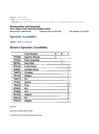
  • 1. Product: TRACK LOADER Model: 977L TRACK LOADER 64X Configuration: 977L TRACK-TYPE LOADER / POWER SHIFT / 64X00001-UP (MACHINE) POWERED BY 3306 ENGINE Disassembly and Assembly 977L TRACK-TYPE TRACTOR POWER TRAIN Media Number -SENR7794-00 Publication Date -01/09/1978 Date Updated -12/10/2001 Sprocket Assemblies SMCS - 4164-11; 4164-12 Remove Sprocket Assemblies start by: a) remove track roller frame 1. Drain the oil from the final drive case. 1/12 977L TRACK-TYPE LOADER / POWER SHIFT / 64X00001-UP (MACHINE) POW... 2021/10/12 https://127.0.0.1/sisweb/sisweb/techdoc/techdoc_print_page.jsp?returnurl=/sis...
  • 2. 2. Remove guard (1), cap (2) and the gasket. 3. Remove lock (5), nut (4), washer assembly (3) and the shims from the sprocket shaft. 4. Remove bearing (6) and the seal from the holder assembly. 5. Remove bolt (8), the nut, lockwasher and lock (9) from holder assembly (7). 2/12 977L TRACK-TYPE LOADER / POWER SHIFT / 64X00001-UP (MACHINE) POW... 2021/10/12 https://127.0.0.1/sisweb/sisweb/techdoc/techdoc_print_page.jsp?returnurl=/sis...
  • 3. 6. Install washer assembly (3) and nut (4) on the sprocket shaft until there is a distance of approximately .125 in. (3.175 mm) between washer assembly (3) and holder assembly (7). Make sure the holes in washer assembly (3) are in alignment with the dowels in holder assembly (7). 7. Hit holder assembly (7) to loosen it from the taper on the sprocket shaft. 8. Fasten a hoist to holder assembly (7). Remove nut (4), washer assembly (3) and holder assembly (7) and the adjustment nut as a unit. The weight of the unit is 80 lb. (36 kg). 9. Remove the outer half of Duo-Cone seal (10) from the adjustment nut. 10. Remove the inner half of Duo-Cone seal (10) from the sprocket. NOTE: Keep the Duo-Cone seals for the sprocket and adjustment nut together so they will not be mixed at assembly. 3/12 977L TRACK-TYPE LOADER / POWER SHIFT / 64X00001-UP (MACHINE) POW... 2021/10/12 https://127.0.0.1/sisweb/sisweb/techdoc/techdoc_print_page.jsp?returnurl=/sis...
  • 4. 11. Remove adjustment nut (11) from holder assembly (7). 12. Remove gasket (12) and seal (13) from hub assembly (7). NOTE: Later machines do not have seal (13). 13. Remove cage (14) from holder assembly (7). 14. Remove bearing cup (15) from cage (14). 4/12 977L TRACK-TYPE LOADER / POWER SHIFT / 64X00001-UP (MACHINE) POW... 2021/10/12 https://127.0.0.1/sisweb/sisweb/techdoc/techdoc_print_page.jsp?returnurl=/sis...
  • 5. 15. Bend the tab of the lock from nut (16). 16. Use tool (A) to loosen nut (16) until it is free from the threads on the sprocket shaft. This will push the bearing cone toward the end of the sprocket shaft. 17. Put tooling (B) in position and pull on nut (16) to remove the nut and bearing (17). 18. Remove the lock for nut (16) from the sprocket shaft. 19. Install nut (16) on the sprocket shaft until there is a clearance of .25 in. (6.35 mm) between the nut and sprocket. Nut (16) is used for protection when the sprocket is loosened from the final drive hub. 20. Remove key (18) from the sprocket shaft. The sprocket is installed with a pressure of 45 to 50 tons (400 to 445 kN). Keep away from the area of the sprocket when it is loosened from the hub with tooling (C). 5/12 977L TRACK-TYPE LOADER / POWER SHIFT / 64X00001-UP (MACHINE) POW... 2021/10/12 https://127.0.0.1/sisweb/sisweb/techdoc/techdoc_print_page.jsp?returnurl=/sis...
  • 6. 21. Install tooling (C) on the end of the sprocket shaft and sprocket (19) as shown. 22. Loosen the sprocket with tooling (C). Remove tooling (C) and nut (16). 23. Fasten a hoist to sprocket (19) and remove it from the final drive hub. The weight of the sprocket is 400 lb. (180 kg). 24. Remove the outer half of Duo-Cone seal (20) from the sprocket. 25. Remove the inner half of Duo-Cone seal (20) from the final drive case. Keep the Duo-Cone seals together so they will not be mixed at assembly. Install Sprocket Assemblies 6/12 977L TRACK-TYPE LOADER / POWER SHIFT / 64X00001-UP (MACHINE) POW... 2021/10/12 https://127.0.0.1/sisweb/sisweb/techdoc/techdoc_print_page.jsp?returnurl=/sis...
  • 7. 1. Make sure the Duo-Cone seals for the final drive case and sprocket are clean and dry. Make sure all metal surfaces that the seals make contact with are clean and dry. Install the Duo-Cone seals in the final drive case and inner side of the sprocket with tool (A). Put a light amount of oil on the metal surfaces of the seals that make contact with each other. 7/12 977L TRACK-TYPE LOADER / POWER SHIFT / 64X00001-UP (MACHINE) POW... 2021/10/12 https://127.0.0.1/sisweb/sisweb/techdoc/techdoc_print_page.jsp?returnurl=/sis...
  • 8. 2. Fasten a hoist to the sprocket (1) and put it in position on the final drive hub. Make sure the splines of the sprocket and the hub are in alignment. Push the sprocket on the hub as far as possible by hand. NOTICE Make sure the splines of the hub and sprocket are clean and dry. 3. Put tooling (B) in position to install sprocket (1) as follows: a) Install the 1P5579 Adapter (2), spacer (3) and coupling (4) on the sprocket shaft as shown. b) Put head (7) in position on cylinder group (9) and install the 6H4158 Pins (8). Install a ring on each side of pins (8) to hold them. c) Install 5P4183 Adapter (6) on the cylinder rod. d) Put sleeve (5) in position as shown. 8/12 977L TRACK-TYPE LOADER / POWER SHIFT / 64X00001-UP (MACHINE) POW... 2021/10/12 https://127.0.0.1/sisweb/sisweb/techdoc/techdoc_print_page.jsp?returnurl=/sis...
  • 9. e) Fasten a hoist to cylinder group (9) and put it in position. Install the 7M9772 Pin (10) to hold the adapters together. 4. Install the sprocket with tooling (B) with a force of 45 to 50 tons (400 to 445 kN). 5. Remove tooling (B) from the sprocket shaft. Check the distance between the end of the splines on the hub and the end of the sprocket with a depth micrometer. The distance must be .281 ± .060 in. (7.14 ± 1.52 mm). 6. Install the lock and nut (11) on the hub. Tighten the nut with tool (C). 7. Bend the tab of the lock over nut (11) to hold it in position. 8. Heat bearing (12) to a maximum temperature of 275° F (135° C). Install the bearing on the hub and against the nut as shown. 9/12 977L TRACK-TYPE LOADER / POWER SHIFT / 64X00001-UP (MACHINE) POW... 2021/10/12 https://127.0.0.1/sisweb/sisweb/techdoc/techdoc_print_page.jsp?returnurl=/sis...
  • 10. 9. Lower the temperature of bearing cup (13). Install the bearing cup in cage (14) until it makes contact with the bottom edge of the cage. 10. Put cage (14) in position in holder assembly (15) with the groove in the cage in alignment with the dowel in the holder assembly. 11. Make sure the groove for the gasket in holder assembly (15) is clean and dry. Install a new seal (17) and gasket (16) in holder assembly (15). NOTE: Put liquid soap on seal (17) for easier installation. Later machines do not have seal (17). 12. Put a thin layer of 5P960 Multipurpose Type Grease on the threads and face of nut (18) that makes contact with the gasket in the holder assembly. Install the nut on the holder. 10/12 977L TRACK-TYPE LOADER / POWER SHIFT / 64X00001-UP (MACHINE) PO... 2021/10/12 https://127.0.0.1/sisweb/sisweb/techdoc/techdoc_print_page.jsp?returnurl=/sis...
  • 11. 13. Install the outer half of the Duo-Cone seal in nut (18) with tool (A). NOTE: The rubber seals and all of the surfaces that make contact with the rubber seals must be clean and dry. Put clean SAE 30 oil on the contact surfaces of the metal seals. 14. Install the inner half of the Duo-Cone seal in the sprocket with tool (A). 15. Fasten a hoist to the holder assembly and put it in position on the sprocket shaft. Make sure the groove in the holder assembly is in alignment with the key on the sprocket shaft. 16. Install lock (19), the bolt, lockwasher and nut for the holder assembly. 11/12 977L TRACK-TYPE LOADER / POWER SHIFT / 64X00001-UP (MACHINE) PO... 2021/10/12 https://127.0.0.1/sisweb/sisweb/techdoc/techdoc_print_page.jsp?returnurl=/sis...
  • 12. 17. Put 1P808 General Purpose Lubricant on the seal for bearing (20) and on the inside diameter of bearing (20). Install the seal in bearing (20) and put the bearing in position. 18. Install shims (21) for the correct alignment of the sprocket and track roller frame. See Alignment of Track Roller Frame in SPECIFICATIONS to find the correct amount of shims needed. 19. Install washer assembly (22) and nut (23). Tighten the nut to a torque of 600 to 700 lb.ft. (810 to 950 N·m). 20. Install lock (24) to hold the nut in position. 21. Install guard (25), the gasket and cap (26) on the bearing. 22. Make an adjustment of the final drive bearings before the track roller frames are installed. See Adjustment for Final Drive Bearings. 23. Fill the final drive case with oil to the correct level. end by: a) install track roller frames 12/12 977L TRACK-TYPE LOADER / POWER SHIFT / 64X00001-UP (MACHINE) PO... 2021/10/12 https://127.0.0.1/sisweb/sisweb/techdoc/techdoc_print_page.jsp?returnurl=/sis...
  • 13. Product: TRACK LOADER Model: 977L TRACK LOADER 64X Configuration: 977L TRACK-TYPE LOADER / POWER SHIFT / 64X00001-UP (MACHINE) POWERED BY 3306 ENGINE Disassembly and Assembly 977L TRACK-TYPE TRACTOR POWER TRAIN Media Number -SENR7794-00 Publication Date -01/09/1978 Date Updated -12/10/2001 Adjustment For Final Drive Bearings SMCS - 4164-11; 4164-12 Adjustment For Final Drive Bearings 1. Use tooling (A) to lift one side of the machine until the track is off the ground. 1/4 977L TRACK-TYPE LOADER / POWER SHIFT / 64X00001-UP (MACHINE) POW... 2021/10/12 https://127.0.0.1/sisweb/sisweb/techdoc/techdoc_print_page.jsp?returnurl=/sis...
  • 14. 2. Install tooling (B) and lower the weight of the machine on tooling (B). 3. Remove guards (1) and (2) from the track roller frame. 4. Remove cap (3) and the gasket from the bearing. 5. Remove bolt (4), the nut, lockwasher and lock (5) from the holder assembly. 6. Remove lock (7) and check the torque on nut (8). The nut must be tightened to a torque of 600 to 700 lb.ft. (810 to 950 N·m). Install lock (7). 7. Use tool (C) to loosen adjustment nut (6). Turn the nut in a clockwise direction to loosen it. 2/4 977L TRACK-TYPE LOADER / POWER SHIFT / 64X00001-UP (MACHINE) POW... 2021/10/12 https://127.0.0.1/sisweb/sisweb/techdoc/techdoc_print_page.jsp?returnurl=/sis...
  • 15. 8. Start the machine and turn the sprocket slowly while adjustment nut (6) is tightened with tooling (D) to a torque of 2500 ± 300 lb.ft. (3380 ± 410 N·m). Tighten nut (6) in a counterclockwise direction. On the left side of the machine the nut is tightened in a counterclockwise direction also. 9. Turn adjustment nut (6) clockwise with tooling (D) (about six to ten lugs) to lower the torque to less than 350 lb.ft. (470 N·m). NOTE: If it is not possible to get a torque below 350 lb.ft. after the adjustment nut is loosened, a separation of the tracks must be made to make the adjustment of the bearings. 10. Use tooling (D) to tighten adjustment nut (6) again to a torque of 350 ± 10 lb.ft. (470 ± 14 N·m). 11. Make a mark on nut (6) and the holder assembly. Tighten nut (6) in a counterclockwise direction 6.36 ± .06 in. (161.5 ± 1.52 mm) of the circumference as measured on the holder assembly outside diameter. 12. If necessary, tighten nut (6) more to install lock (5) in one of the notches of adjustment nut (6). Install the bolt, nut and lockwasher to hold the lock in position. 13. Install the gasket and cap (3). 3/4 977L TRACK-TYPE LOADER / POWER SHIFT / 64X00001-UP (MACHINE) POW... 2021/10/12 https://127.0.0.1/sisweb/sisweb/techdoc/techdoc_print_page.jsp?returnurl=/sis...
  • 16. 14. Install guards (1) and (2) on the track roller frame. 15. Lift the machine with tooling (A) and remove tooling (B). Lower the machine to the ground and remove tooling (A). 4/4 977L TRACK-TYPE LOADER / POWER SHIFT / 64X00001-UP (MACHINE) POW... 2021/10/12 https://127.0.0.1/sisweb/sisweb/techdoc/techdoc_print_page.jsp?returnurl=/sis...
  • 17. Product: TRACK LOADER Model: 977L TRACK LOADER 64X Configuration: 977L TRACK-TYPE LOADER / POWER SHIFT / 64X00001-UP (MACHINE) POWERED BY 3306 ENGINE Disassembly and Assembly 977L TRACK-TYPE TRACTOR POWER TRAIN Media Number -SENR7794-00 Publication Date -01/09/1978 Date Updated -12/10/2001 Final Drive Cases, Gears, Idler Pinions And Bearings SMCS - 4059; 4075-11; 4075-12 Remove Final Drive Cases, Gears, Idler Pinions And Bearings start by: a) remove sprocket assemblies 1/9 977L TRACK-TYPE LOADER / POWER SHIFT / 64X00001-UP (MACHINE) POW... 2021/10/12 https://127.0.0.1/sisweb/sisweb/techdoc/techdoc_print_page.jsp?returnurl=/sis...
  • 18. 1. Remove the bolts that hold final drive case (1) in position. 2. Install three 1/2"-13 NC guide pins (3) through the final drive case and into the steering clutch case. Install two 1/2"-13 NC forcing screws (2) in the final drive case. Tighten the screws evenly until the case is approximately .25 in. (6.35 mm) away from the steering clutch case. 3. Install a piece of wire around two of the guide pins to hold the idler pinion in place. NOTICE The wire is to keep the planet carrier in position so it will not fall from the steering clutch case when the final drive case is removed. 4. Tighten the forcing screws until tool (A) and a hoist can be fastened to final drive case (1). Remove case (1) from the guide pins. The weight of the final drive case is 250 lb. (113 kg). 5. Remove the plugs from case (1) with tool group (B). 2/9 977L TRACK-TYPE LOADER / POWER SHIFT / 64X00001-UP (MACHINE) POW... 2021/10/12 https://127.0.0.1/sisweb/sisweb/techdoc/techdoc_print_page.jsp?returnurl=/sis...
  • 19. 6. Remove the dowels from case (1) with a 1/4"-20 NC bolt. 7. Use tooling (C) to remove race and roller assemblies (4) and (5) from the final drive case. 8. Fasten a hoist to the gear and hub (6). Remove the gear and hub from the sprocket shaft. The weight of the gear and hub is 265 lb. (119 kg). 9. Put the gear and hub on wood blocks. Remove the bearing cone from the hub with tooling (D). 10. Remove the nuts from bolts (8). Use a hammer and soft punch to remove bolts (8) from gear (7) and hub (6) as shown. 3/9 977L TRACK-TYPE LOADER / POWER SHIFT / 64X00001-UP (MACHINE) POW... 2021/10/12 https://127.0.0.1/sisweb/sisweb/techdoc/techdoc_print_page.jsp?returnurl=/sis...
  • 20. 11. Use a nylon strap and a pin or bolt with a length that is longer than the inside diameter of hub (6) to fasten a hoist to the hub. Remove hub (6) from gear (7). The weight of the hub is 145 lb. (65 kg). 12. If necessary, remove bearing cup (9) from the steering clutch case. 13. Remove the wire from the gear and pinion. Fasten a hoist and remove gear (10) and the pinion from the steering clutch case. The weight of the gear and pinion is 75 lb. (34 kg). 14. Put the gear and pinion on wood blocks. Use tooling (E) to remove the bearing races (11) from each end of the pinion shaft. 15. Remove the pinion shaft from the gear as follows: a) Put the gear and pinion shaft in a press as shown. 4/9 977L TRACK-TYPE LOADER / POWER SHIFT / 64X00001-UP (MACHINE) POW... 2021/10/12 https://127.0.0.1/sisweb/sisweb/techdoc/techdoc_print_page.jsp?returnurl=/sis...
  • 21. TYPICAL EXAMPLE b) Put a small amount of pressure on the pinion shaft with the press. Push the ring in the groove on the pinion shaft with a hammer and punch. The ring will stay in the groove because of the pressure on the pinion shaft. c) When the ring is completely in the groove, the pinion shaft will slide out of the gear. NOTICE Too much pressure on the pinion shaft can cause damage to the gear. 16. If necessary, remove bearing race (12) with tooling (E). 17. Use three 1/2"-13 NC forcing screws to remove cage (13) from the steering clutch case. 5/9 977L TRACK-TYPE LOADER / POWER SHIFT / 64X00001-UP (MACHINE) POW... 2021/10/12 https://127.0.0.1/sisweb/sisweb/techdoc/techdoc_print_page.jsp?returnurl=/sis...
  • 22. 18. Use a 1/4"-20 NC bolt to remove the dowel from cage (13). Remove O-ring seal (14) from the cage. 19. Use tooling (C) to remove the race and roller assembly from the cage. Install Final Drive Cases, Gears, Idler Pinions And Bearings 1. Lower the temperature of roller and race assembly (1) and install it in cage (2). Make sure the hole in the race and roller assembly is in alignment with the hole in cage (2) at assembly. 2. Put clean oil on O-ring seal (4) and install it on cage (2). 6/9 977L TRACK-TYPE LOADER / POWER SHIFT / 64X00001-UP (MACHINE) POW... 2021/10/12 https://127.0.0.1/sisweb/sisweb/techdoc/techdoc_print_page.jsp?returnurl=/sis...
  • 23. 3. Install dowel (3) to hold the race and roller assembly in cage (2). 4. Heat bearing race (5) to a maximum temperature of 275°F (135°C). Install bearing race (5) on the pinion as shown. 5. Lower the temperature of bearing cup (6) and install it in the steering clutch case as shown. 6. Install the bearing and cage (2) in the steering clutch case. Make sure the oil groove next to the bearing in the cage is at the bottom before the bolts are tightened. 7. If a separation of the idler gear and pinion was made, install a new retainer in the pinion. Install the gear over the pinion so the deep chamfer is used to put the retainer under compression. Make sure the retainer is engaged in the groove of the gear. 8. Heat bearing races (7) and (8) to a maximum temperature of 275°F (135°C) and install them on the idler pinion. 9. Put 1P808 General Purpose Lubricant in the bearing to hold the rollers out for installation of gear (9) and the pinion. Fasten a hoist to the gear and pinion. Install the gear (9) and pinion in the steering clutch case. 10. Install three 1/2"-13 NC guide pins in the steering clutch case for installation of the final drive case. Fasten a wire around the guide bolts, idler gear (9) and the pinion. 7/9 977L TRACK-TYPE LOADER / POWER SHIFT / 64X00001-UP (MACHINE) POW... 2021/10/12 https://127.0.0.1/sisweb/sisweb/techdoc/techdoc_print_page.jsp?returnurl=/sis...
  • 24. NOTE: The wire will hold idler gear (9) and the pinion in position until the final drive case is installed. 11. Fasten a hoist to hub (10) and put it in position in gear (11). Install the bolts, washers and nuts that hold the hub and gear together. 12. Heat bearing cone (12) to a maximum temperature of 275° F (135° C). Install the bearing cone on the hub as shown. 13. Fasten a hoist to hub (10) and the gear. Put hub (10) and the gear in position on the sprocket shaft. 14. Lower the temperature of race and roller assemblies (14) and (15). Install the race and roller assemblies in case (13). Make sure the hole in the race and roller assemblies are in alignment with the dowel holes in case (13). 8/9 977L TRACK-TYPE LOADER / POWER SHIFT / 64X00001-UP (MACHINE) POW... 2021/10/12 https://127.0.0.1/sisweb/sisweb/techdoc/techdoc_print_page.jsp?returnurl=/sis...
  • 25. 15. Install dowel (16) and the plug in case (13) to hold race and roller assembly (15). Install the dowel and plug to hold race and roller assembly (14). Put 1P808 General Purpose Lubricant in the race and roller assemblies to hold the rollers out to prevent damage of parts when case (13) is installed. 16. Fasten a hoist to case (13) with tool (A). Put 7M7260 Liquid Gasket Material on the machined surface of the steering clutch case and case (13). 17. Put case (13) on the guide pins. Removo tool (A) and the wire used to hold the idler pinion. Install the bolts and washers that hold case (13). Tighten the bolts to a torque of 100 ± 10 lb.ft. (135 ± 14 N·m). 18. Fill the steering clutch case and final drive cases with oil to the correct level. See LUBRICATION AND MAINTENANCE GUIDE. end by: a) install sprocket assemblies 9/9 977L TRACK-TYPE LOADER / POWER SHIFT / 64X00001-UP (MACHINE) POW... 2021/10/12 https://127.0.0.1/sisweb/sisweb/techdoc/techdoc_print_page.jsp?returnurl=/sis...
  • 26. Product: TRACK LOADER Model: 977L TRACK LOADER 64X Configuration: 977L TRACK-TYPE LOADER / POWER SHIFT / 64X00001-UP (MACHINE) POWERED BY 3306 ENGINE Disassembly and Assembly 977L TRACK-TYPE TRACTOR POWER TRAIN Media Number -SENR7794-00 Publication Date -01/09/1978 Date Updated -12/10/2001 Sprocket Shafts SMCS - 4058-11; 4058-12 Remove Sprocket Shafts start by: a) remove final drive cases, gears, idler pinions and bearings 1/5 977L TRACK-TYPE LOADER / POWER SHIFT / 64X00001-UP (MACHINE) POW... 2021/10/12 https://127.0.0.1/sisweb/sisweb/techdoc/techdoc_print_page.jsp?returnurl=/sis...
  • 27. VIEW FROM UNDER MACHINE 1. Remove ring (2) and the pin from spanner nut (1). 2. Loosen nut (1) with tool (A) until there is a clearance of .125 in. (3.2 mm) between the nut and the steering clutch case. Do not remove nut (1) from the sprocket shaft threads until the shaft is loosened with tooling (B). The nut will hold the shaft when it is loosened from the taper in the steering clutch case. 3. Install tooling (B) to remove the sprocket shaft as follows: a) Install the 5P4183 Adapter on the end of the sprocket shaft. Put the 5P4181 Adapter in the 5P4183 Adapter and install a 7M9772 Pin to hold the adapters together. Install a wire or 3P1770 Pin on each side of the pin to hold it in position. b) Install the 7M9773 Adapter on the 5P4181 Adapter. c) Connect the 9H3992 Head to the cylinder group with the 6H4158 Pins. Put a 7B2499 Ring on each side of the pins to hold them. d) Install the 7M9774 Coupling on the end of the cylinder group. e) Fasten a hoist to the cylinder group and put it in position on the sleeve. f) Install a 7M9772 Pin through the 7M9774 Coupling and 5P4181 Adapter. Put a wire or 3P1770 Pin on each side of the 7M9772 Pin to hold it. 4. Fasten a hoist to tooling (B) and loosen the sprocket shaft. Remove tooling (B). Remove nut (1) from the sprocket shaft threads. 2/5 977L TRACK-TYPE LOADER / POWER SHIFT / 64X00001-UP (MACHINE) POW... 2021/10/12 https://127.0.0.1/sisweb/sisweb/techdoc/techdoc_print_page.jsp?returnurl=/sis...
  • 28. 5. Fasten a hoist to sprocket shaft (3) and remove it from the steering clutch case. The weight of the sprocket shaft is 100 lb. (45 kg). Install Sprocket Shafts 1. Fasten a hoist to sprocket shaft (1) and put it in the steering clutch case as far as possible by hand. 2. Put the spanner nut on the end of the sprocket shaft under the steering clutch case. 3/5 977L TRACK-TYPE LOADER / POWER SHIFT / 64X00001-UP (MACHINE) POW... 2021/10/12 https://127.0.0.1/sisweb/sisweb/techdoc/techdoc_print_page.jsp?returnurl=/sis...
  • 29. Suggest: If the above button click is invalid. Please download this document first, and then click the above link to download the complete manual. Thank you so much for reading
  • 30. 3. Install tooling (A) on the end of the sprocket shaft. Use a hammer to push sprocket shaft (1) until the spanner nut can be installed on the threads. 4. Install tooling (B) on the sprocket shaft as shown. Fasten a hoist to the tooling. Install the sprocket shaft with tooling (B) with a force of 20 to 30 tons (180 to 265 kN). 5. Tighten the spanner nut with tool (C) while the pressure is still on the sprocket shaft. Tighten the nut to a torque of 700 ± 50 lb.ft. (950 ± 70 N·m). 6. After the spanner nut is tightened, release the pressure on the sprocket shaft and remove tooling (B). 7. Install holder assembly (2), the shims, washer assembly and nut on the sprocket shaft. Tighten the nut to a torque of 600 to 700 lb.ft. (810 to 950 N·m). 8. Measure the distance from the face of the holder assembly to the steering clutch case. Distance "X" must be 11.995 ± .062 in. (304.7 ± 1.57 mm) for a standard size sprocket shaft and 14.995 ± .062 in. (380.9 ± 1.57 mm) for a Low Ground Pressure sprocket shaft. 9. To fasten nut (3) in position make a .368 in. (9.35 mm) hole in one of the grooves in nut (3). Drill the hole through the nut and .75 in. (19.1 mm) deep in the sprocket shaft. Install pin (5) and ring (4). end by: 4/5 977L TRACK-TYPE LOADER / POWER SHIFT / 64X00001-UP (MACHINE) POW... 2021/10/12 https://127.0.0.1/sisweb/sisweb/techdoc/techdoc_print_page.jsp?returnurl=/sis...