
Recommended
Recommended
More Related Content
What's hot
What's hot (20)
Similar to QUICK REFERENCE FOR 2004 SENTRA 1.8L AND 2.5L ENGINES
Similar to QUICK REFERENCE FOR 2004 SENTRA 1.8L AND 2.5L ENGINES (20)
Recently uploaded
Recently uploaded (20)
QUICK REFERENCE FOR 2004 SENTRA 1.8L AND 2.5L ENGINES
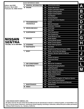
- 1. -1 QUICK REFERENCE INDEX A GENERAL INFORMATION GI General Information B ENGINE EM Engine Mechanical LU Engine Lubrication System CO Engine Cooling System EC Engine Control System FL Fuel System EX Exhaust System ACC Accelerator Control System C TRANSMISSION/ TRANSAXLE CL Clutch MT Manual Transaxle AT Automatic Transaxle D DRIVELINE/AXLE FAX Front Axle RAX Rear Axle E SUSPENSION FSU Front Suspension RSU Rear Suspension WT Road Wheels & Tires F BRAKES BR Brake System PB Parking Brake System BRC Brake Control System G STEERING PS Power Steering System H RESTRAINTS SB Seat Belts SRS Supplemental Restraint System (SRS) I BODY BL Body, Lock & Security System GW Glasses, Window System & Mirrors RF Roof EI Exterior & Interior IP Instrument Panel SE Seat J AIR CONDITIONER MTC Manual Air Conditioner K ELECTRICAL SC Starting & Charging System LT Lighting System DI Driver Information System WW Wiper, Washer & Horn BCS Body Control System LAN LAN System AV Audio Visual, Navigation & Telephone System ACS Auto Cruise Control System PG Power Supply, Ground & Circuit Elements L MAINTENANCE MA Maintenance M INDEX IDX Alphabetical Index Edition: April 2003 Revision: March 2004 Publication No. SM4E-1B15U1 B D © 2004 NISSAN NORTH AMERICA, INC. All rights reserved. No part of this Service Manual may be reproduced or stored in a retrieval system, or transmitted in any form, or by any means, electronic, mechanical, photo-copying, recording or otherwise, without the prior written permission of Nissan North America, Inc., Gardena, California. A C E F G H I J K L M
- 2. -2 This manual contains maintenance and repair procedures for the 2004 NISSAN SENTRA. In order to assure your safety and the efficient functioning of the vehicle, this manual should be read thoroughly. It is especially important that the PRECAUTIONS in the GI section be completely understood before starting any repair task. All information in this manual is based on the latest product information at the time of publication. The right is reserved to make changes in specifi- cations and methods at any time without notice. IMPORTANT SAFETY NOTICE The proper performance of service is essential for both the safety of the technician and the efficient functioning of the vehicle. The service methods in this Service Manual are described in such a manner that the service may be performed safely and accurately. Service varies with the procedures used, the skills of the technician and the tools and parts available. Accordingly, anyone using service procedures, tools or parts which are not specifically recommended by NISSAN must first be completely satisfied that neither personal safety nor the vehicle’s safety will be jeopardized by the service method selected.
- 3. QUICK REFERENCE CHART: SENTRA (EQUIPPED WITH 1.8L, QG ENGINE) 2004 QUICK REFERENCE CHART: SENTRA (EQUIPPED WITH 1.8L, QG ENGINE) PFP:00027 Engine Tune-Up Data ELS000L4 Drive Belt Deflection and Tension *1: If the belt tension gauge cannot be installed at check points shown, check belt tension at a different location on the belt. Spark Plugs (Double Platinum - Tipped) Front Wheel Alignment (Unladen*1) ELS000L6 Unit: degree minute (decimal degree) Engine QG18DE Classification Gasoline Cylinder arrangement 4 in-line Displacement 1,769 cm3 (107.94 cu in) Bore × stroke 80.0 × 88.0 mm (3.150 × 3.465 in) Valve arrangement DOHC Firing order 1-3-4-2 Number of piston rings Compression 2 Oil 1 Number of main bearings 5 Compression ratio 9.5: 1 Component Deflection Adjustment Unit: mm (in) Tension Adjustment*1 Unit: N (kg, lb) Used Belt New Belt Used Belt New Belt Limit After Adjustment Limit After Adjustment Generator With air con- ditioner com- pressor 8.1 (0.319) 5.3 - 5.7 (0.209 - 0.244) 4.5 - 5.0 (0.177- 0.197) 292 (30, 66) 652 - 740 (66.5 - 75.5, 146.6 - 166.4) 789 - 877 (80.5 - 89.5, 177.4 - 197.1) Without air conditioner compressor 10.2 (0.402) 6.5 - 7.0 (0.256 - 0.276) 5.5 - 6.1 (0.217 - 0.240) 292 (30, 60) 652 - 740 (66.5 - 75.5, 146.6 - 166.4) 789 - 877 (80.5 - 89.5, 177.4 - 197.1) Power steering oil pump 7.1 (0.280) 4.4 - 4.9 (0.173 - 0.193) 3.9 - 4.4 (0.154 - 0.173) 196 (20, 44) 495 - 583 (50.5 -59.5, 111.4 - 131.2) 603- 691 (61.5 - 70.5, 135.6 - 155.5) Applied pushing force 98 N (10 kg, 22 lb) — Type Hot PLFR4A-11 Standard PLFR5A-11 Cold PLFR6A-11 Plug gap (nominal) 1.1 mm (0.043 in) Camber Minimum −1°10' (−1.17°) Nominal −0°25' (−0.42°) Maximum 0°20′ (0.33°) Left and right difference 45′ (0.75°) or less Caster Minimum 0°51′ (0.85°) Nominal 1°36′ (1.60°) Maximum 2°21′ (2.35°) Left and right difference 45′ (0.75°) or less
- 4. 2004 QUICK REFERENCE CHART: SENTRA (EQUIPPED WITH 1.8L, QG ENGINE) *1: Fuel, radiator coolant and engine oil full. Spare tire, jack, hand tools and floor mats in designated positions. *2: On power steering models, wheel turning force (at circumference of steering wheel) of 98 - 147 N (10 - 15 kg, 22 - 33 lb) with engine running at idle. Rear Wheel Alignment (Unladen*) ELS000L7 Unit: degree minute (decimal degree) *: Fuel, radiator coolant and engine oil full. Spare tire, jack, hand tools and mats in designated positions. Brake ELS000L8 Unit: mm (in) Kingpin inclination Degree minute (decimal degree) Minimum 13°58′ (13.97°) Nominal 14°43′ (14.72°) Maximum 15°28′ (15.47°) Total toe-in Distance Minimum 1 mm (0.039 in) Nominal 2 mm (0.079 in) Maximum 3 mm (0.118 in) Angle (left plus right) Minimum 5.5′ (0.08°) Nominal 11′ (0.18°) Maximum 16′ (0.27°) Wheel turning angle Full turn*2 Inside Minimum 34° (34.0°) Nominal 37° (37.0°) Maximum 38° (38.0°) Outside Nominal 31° (31.0°) Camber Minimum −1°45′ (−1.75°) Nominal −1°00′ (−1.00°) Maximum −0°15′ (−0.25°) Total toe-in Distance Minimum −3 mm (−0.12 in) Nominal 1 mm (0.04 in) Maximum 5 mm (0.20 in) Angle (left plus right) Minimum −16′ (−0.27°) Nominal 5′30″ (0.09°) Maximum 26′ (0.43°) Front brake Brake model CL25VA Cylinder bore diameter 57.2 (2.252) Pad length × width × thickness 125.6 × 46.0 × 11.0 (4.94 × 1.811 × 0.433) Rotor outer diameter × thickness 257 × 22 (10.12 × 0.87) Rear brake Brake model LT20G Cylinder bore diameter/caliper bore diameter 15.87 (5/8) type a 17.45 (11/16) type b Lining length × width × thickness 219.4 × 35 × 4.5 (8.64 × 1.38 × 0.177) Drum inner diameter/Disc diameter × thickness 203.2 (8) Master cylinder Cylinder bore diameter 23.81 (15/16) Control valve Valve model Dual proportioning valve Split point 1,961 kPa (20 kg/cm2, 284 psi)] × 0.2 reducing ratio
- 5. QUICK REFERENCE CHART: SENTRA (EQUIPPED WITH 1.8L, QG ENGINE) 2004 Disc Brake - Repair Limits Unit: mm (in) Drum Brake - Repair Limits Unit: mm (in) Refill Capacities ELS000LC Engine Coolant Capacity (Approximate) Unit: (US qt, Imp qt) Engine Oil Capacity (Approximate) Unit: (US qt, Imp qt) Miscellaneous Capacities (Approximate) Brake booster Booster model M215T Diaphragm diameter Primary: 230 (9.06) Secondary: 205 (8.07) Brake fluid Recommended brake fluid Genuine NISSAN Super Heavy Duty Brake Fluid or equivalent DOT 3 (US FMVSS No. 116) Brake model CL25VA Pad wear limit Minimum thickness 2.0 (0.079) Rotor repair limit Minimum thickness 20 (0.79) Brake model LT20G Lining wear limit Minimum thickness 1.5 (0.059) Drum repair limit Maximum inner diameter 204.5 (8.05) Maximum out-of round 0.03 (0.0012) Drain and refill without reservoir M/T (RS5F70A) 6.0 (6 3/8, 5 1/4) A/T (RE4F03B) 5.9 (6 1/4, 5 1/4) Reservoir tank (at MAX level) 0.7 (3/4, 5/8) Drain and refill With oil filter change 2.7 (2 7/8, 2 3/8) Without oil filter change 2.5 (2 5/8, 2 1/4) Dry engine (engine overhaul) 3.1 (3 1/4, 2 3/4) Fuel tank 50 13 1/4 US gal 11 Imp gal Power steering system 1.0 1 1/8 US qt 1 3/4 Imp qt Transaxle M/T (RS5F70A) 3.0 3 1/8 US qt 2 5/8 Imp qt A/T (RE4F03B) 7.0 7 3/8 US qt 6 1/8 Imp qt Air conditioning system Refrigerant 0.45 - 0.55 kg 0.99 - 1.21 lb 0.99 - 1.21 lb Compressor oil 180 m 6.1 US fl oz 6.3 Imp fl oz
- 6. QUICK REFERENCE CHART: SENTRA (EQUIPPED WITH 2.5L, QR ENGINE) 2004 QUICK REFERENCE CHART: SENTRA (EQUIPPED WITH 2.5L, QR ENGINE) PFP:00027 Engine Tune-Up Data ELS000LF Drive Belt Deflection and Tension Spark Plugs (Double Platinum Tipped) Front Wheel Alignment (Unladen*1) ELS000LI Unit: degree minute (decimal degree) Engine QR25DE Cylinder arrangement 4 in-line Displacement 2,488 cm3 (151.82 cu in) Bore and stroke 89.0 x 100 mm (3.50 - 3.94 in) Valve arrangement DOHC Firing order 1-3-4-2 Number of piston rings Compression 2 Oil 1 Compression ratio 9.5 Compression pressure Standard 1,250 kPa (12.8 kg/cm2, 182 psi) / 250 rpm Minimum 1,060 kPa (10.8 kg/cm2 , 154 psi) / 250 rpm Differential limit between cylinders 100 kPa (1.0 kg/cm2, 14 psi) / 250 rpm Tension of drive belts Auto adjustment by auto-tensioner Type Standard PLFR5A-11 Hot PLFR4A-11 Cold PLFR6A-11 Plug gap (nominal) 1.1 mm (0.043 in) Camber Minimum −1°12' (−1.2°) Nominal −0°27' (−0.45°) Maximum 0°18′ (0.3°) Left and right difference 45′ (0.75°) or less Caster Minimum 0°58′ (0.97°) Nominal 1°43′ (1.72°) Maximum 2°28′ (2.47°) Left and right difference 45′ (0.75°) or less Kingpin inclination Minimum 14°03′ (14.05°) Nominal 14°46′ (14.77°) Maximum 15°31′ (15.52°) Total toe-in Distance Minimum 1 mm (0.039 in) Nominal 2 mm (0.079 in) Maximum 3 mm (0.118 in) Angle (left plus right) Minimum 5.5′ (0.08°) Nominal 11′ (0.18°) Maximum 16′ (0.27°)
- 7. 2004 QUICK REFERENCE CHART: SENTRA (EQUIPPED WITH 2.5L, QR ENGINE) *1: Fuel, radiator coolant and engine oil full. Spare tire, jack, hand tools and mats in designated positions. *2: On power steering models, wheel turning force (at circumference of steering wheel) of 98 to 147 N (10 to 15 kg, 22 to 33 lb) with engine idle. Rear Wheel Alignment (Unladen*) ELS000LJ Unit: degree minute (decimal degree) *: Fuel, radiator coolant and engine oil full. Spare tire, jack, hand tools and mats in designated positions. Brake ELS000LK Unit: mm (in) Disc Brake - Repair Limits Unit: mm (in) Wheel turning angle Full turn*2 Inside Minimum 29° (29.0°) Nominal 32° (32.0°) Maximum 33° (33.0°) Outside Nominal 27° (27.0°) Camber Minimum −1°45′ (−1.75°) Nominal −1°00′ (−1.00°) Maximum −0°15′ (−0.25°) Total toe-in Distance Minimum −3 mm (−0.12 in) Nominal 1 mm (0.04 in) Maximum 5 mm (0.20 in) Angle (left plus right) Minimum −16′ (−0.27°) Nominal 5′30″ (0.09°) Maximum 26′ (0.43°) Front brake Brake model CL25VB OPB27VA Cylinder bore diameter 57.2 (2.252) 38 (1.50) x 2 + 44 (1.73) x 2 Pad length × width × thickness 125.6 × 46.0 × 11.0 (4.94 × 1.811 × 0.433) 117.1 x 53.3 x 9.3 (4.61 x 2.098 x 0.366) Rotor outer diameter × thickness 280 × 22 (11.02 × 0.87) 324 x 30.0 (12.76 x 1.181) Rear brake Brake model CL9HC Cylinder bore diameter/caliper bore diameter 33.96 (1 11/32) Lining length × width × thickness 89.1 × 39.5 × 10 (3.508 × 1.555 × 0.39) Drum inner diameter/Disc diameter × thickness 258 × 9 (10.16 × 0.35) Master cylinder Cylinder bore diameter 23.81 (15/16) Control valve Valve model Dual proportioning valve Split point 2,942 kPa (30 kg/cm2 , 427 psi)] × 0.2 reducing ratio Brake booster Booster model M215T Diaphragm diameter Primary: 230 (9.06) Secondary: 205 (8.07) Brake fluid Recommended brake fluid Genuine NISSAN Super Heavy Duty Brake Fluid or equivalent DOT 3 (US FMVSS No. 116) Brake model CL25VB (Front) OPB27VA (Front) CL9HC (Rear) Pad wear limit Minimum thickness 2.0 (0.079) 2.0 (0.079) 2.0 (0.079) Rotor repair limit Minimum thickness 20 (0.79) 28.4 (1.118) 8.0 (0.31)
- 8. QUICK REFERENCE CHART: SENTRA (EQUIPPED WITH 2.5L, QR ENGINE) 2004 Refill Capacities ELS000LN Engine Coolant Capacity (Approximate) Unit: (US qt, Imp qt) Engine Oil Capacity (Approximate) Unit: (US qt, Imp qt) Miscellaneous Capacity (Approximate) Drain and refill (without reservoir) M/T (RS5F51A, RS6F51H) 6.1 (6 1/2, 5 3/8) A/T (RE4F04B) 6.0 (6 3/8, 5 1/4) Reservoir tank (at MAX level) 0.7 (3/4, 5/8) Drain and refill With oil filter change 4.0 (4 1/4, 3 1/2) Without oil filter change 3.8 (4, 3 3/8) Dry engine (engine overhaul) 4.5 (4 3/4, 4) Fuel tank 50 13 1/4 US gal 11 Imp gal Power steering system 1.0 1 1/8 US qt 1 3/4 Imp qt Transaxle M/T (RS5F51A, RS6F51H) 2.3 2 3/8 US qt 2 Imp qt A/T (RE4F04B) 8.5 9 US qt 7 1/2 Imp qt Air conditioning system Refrigerant 0.45 - 0.55 kg 0.99 - 1.21 lb 0.99 - 1.21 lb Compressor oil 180 m 6.1 US fl oz 6.3 Imp fl oz
- 9. Thank you very much for your reading. Please Click Here Then Get More Information. NOTE: If there is no response to click on the link above, please download the PDF document first and then click on it.
- 10. Attachment No.34 TID CID P0420 01H 01H Max. 1/128 P0420 02H 81H Max. 1 EVAP control system (Small leak) P0442 05H 03H Max. 1/128mm2 EVAP control system purge flow monitoring P0441 06H 83H Min. 20mV EVAP control system (Very small leak) P0456 07H 03H Max. 1/128mm2 P1281 4CH 8FH Min. 5mV P1282 4DH 0FH Max. 5mV P1283 4EH 0FH Max. 0.002 P1284 4FH 8FH Min. 0.002 P1288 50H 8FH Min. 0.004 P1286 51H 0FH Max. 5mV P1286 52H 8FH Min. 5mV P1289 53H 8FH Min. 0.004 P0139 19H 86H Min. 10mV/500ms P1147 1AH 86H Min. 10mV P1146 1BH 06H Max. 10mV P0138 1CH 06H Max. 10mV P1032 57H 04H Max. 5mV P1031 58H 04H Min. 5mV P0038 2DH 0AH Max. 10mV P0037 2EH 8AH Min. 10mV TEST VALUE AND TEST LIMIT (GST ONLY — NOT APPLICABLE TO CONSULT-II) These data (test value and test limit) are specified by Test ID (TID) and Component ID (CID) and can be dis- played on the GST screen. The following is the information specified in Mode 6 of SAE J1979. The test value is a parameter used to determine whether a system/circuit diagnostic test is “OK” or “NG” while being monitored by the ECM during self-diagnosis. The test limit is a reference value which is specified as the maximum or minimum value and is compared with the test value being monitored. Test limit Conversion CATALYST Three way catalyst function SRT item Self-diagnostic test item DTC Test value (GST display) HO2S HTR A/F sensor 1 heater Heated oxygen sensor 2 heater EVAP SYSTEM HO2S A/F sensor 1 Heated oxygen sensor 2
- 11. Attachment No.33 TID CID P0420 01H 01H Max. 1/128 P0420 02H 81H Min. 1 EVAP control system (Small leak) P0442 05H 03H Max. 1/128mm2 EVAP control system purge flow monitoring P0441 06H 83H Min. 20mV EVAP control system (Very small leak) P0456 07H 03H Max. 1/128mm2 P0133 09H 04H Max. 16ms P1143 0AH 84H Min. 10mV P1144 0BH 04H Max. 10mV P0132 0CH 04H Max. 10mV P0134 0DH 04H Max. 1s P0139 19H 86H Min. 10mV/500ms P1147 1AH 86H Min. 10mV P1146 1BH 06H Max. 10mV P0138 1CH 06H Max. 10mV P0032 29H 08H Max. 20mV P0031 2AH 88H Min. 20mV P0038 2DH 0AH Max. 20mV P0037 2EH 8AH Min. 20mV TEST VALUE AND TEST LIMIT (GST ONLY — NOT APPLICABLE TO CONSULT-II) The following is the information specified in Mode 6 of SAE J1979. The test value is a parameter used to determine whether a system/circuit diagnostic test is “OK” or “NG” while being monitored by the ECM during self-diagnosis. The test limit is a reference value which is specified as the Test limit Conversion maximum or minimum value and is compared with the test value being monitored. These data (test value and test limit) are specified by Test ID (TID) and Component ID (CID) and can be dis- played on the GST screen. SRT item Self-diagnostic test item DTC Test value (GST display) CATALYST Three way catalyst function EVAP SYSTEM HO2S Heated oxygen sensor 1 Heated oxygen sensor 2 HO2S HTR Heated oxygen sensor 1 heater Heated oxygen sensor 2 heater