Plano de teste Denso 096000-5260 (VE4/10F2500RND526)
•
0 likes•320 views

Plano de teste bomba denso 096000-526# (VE4/10F2500RND526)

Recommended
Recommended
More Related Content
What's hot
What's hot (20)
Similar to Plano de teste Denso 096000-5260 (VE4/10F2500RND526)
Similar to Plano de teste Denso 096000-5260 (VE4/10F2500RND526) (19)
More from Junior Iung
More from Junior Iung (12)
Recently uploaded
Recently uploaded (20)
Plano de teste Denso 096000-5260 (VE4/10F2500RND526)
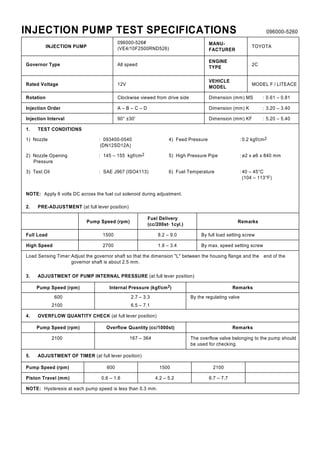
- 1. INJECTION PUMP TEST SPECIFICATIONS 096000-5260 INJECTION PUMP 096000-526# (VE4/10F2500RND526) MANU- FACTURER TOYOTA Governor Type All speed ENGINE TYPE 2C Rated Voltage 12V VEHICLE MODEL MODEL F / LITEACE Rotation Clockwise viewed from drive side Dimension (mm) MS : 0.61 – 0.81 Injection Order A – B – C – D Dimension (mm) K : 3.20 – 3.40 Injection Interval 90° ±30' Dimension (mm) KF : 5.20 – 5.40 1. TEST CONDITIONS 1) Nozzle : 093400-0540 (DN12SD12A) 4) Feed Pressure : 0.2 kgf/cm2 2) Nozzle Opening Pressure : 145 – 155 kgf/cm2 5) High Pressure Pipe : ø2 x ø6 x 840 mm 3) Test Oil : SAE J967 (ISO4113) 6) Fuel Temperature : 40 – 45°C (104 – 113°F) NOTE: Apply 6 volts DC across the fuel cut solenoid during adjustment. 2. PRE-ADJUSTMENT (at full lever position) Pump Speed (rpm) Fuel Delivery (cc/200st. 1cyl.) Remarks Full Load 1500 8.2 – 9.0 By full load setting screw High Speed 2700 1.8 – 3.4 By max. speed setting screw Load Sensing Timer:Adjust the governor shaft so that the dimension "L" between the housing flange and the end of the governor shaft is about 2.5 mm. 3. ADJUSTMENT OF PUMP INTERNAL PRESSURE (at full lever position) Pump Speed (rpm) Internal Pressure (kgf/cm2) Remarks 600 2.7 – 3.3 By the regulating valve 2100 6.5 – 7.1 4. OVERFLOW QUANTITY CHECK (at full lever position) Pump Speed (rpm) Overflow Quantity (cc/1000st) Remarks 2100 167 – 364 The overflow valve belonging to the pump should be used for checking. 5. ADJUSTMENT OF TIMER (at full lever position) Pump Speed (rpm) 600 1500 2100 Piston Travel (mm) 0.6 – 1.6 4.2 – 5.2 6.7 – 7.7 NOTE: Hysteresis at each pump speed is less than 0.3 mm.
- 2. 096000-5260 6. ADJUSTMENT OF FUEL DELIVERY Lever Position Pump speed (rpm) Fuel Delivery (cc/200st, 1cyl) Max. Spread In Delivery (cc) Boost Pressure Absolute Pressure (mmHg) Remarks FULL 1500 8.4 – 8.8 0.4 — By full load setting screw 2700 2600 2.0 – 3.2 4.5 – 6.3 — — — — By max. speed setting screw 100 8.6 – 13.4 0.4 — Lever position : full/idle 500 2350 2500 7.0 – 7.9 7.3 – 8.2 6.3 – 8.2 0.5 0.5 0.5 — — — By governor sleeve plug — — — — 7. SETTING OF LOAD SENSING TIMER N.A. : Not Applicable Pump Speed (rpm) Fuel Delivery (cc/200st, 1cyl) Remarks Start of Load Sensing 1500 Full-load delivery – (0.7 – 1.3 ) By governor shaft End of Pressure Drop 1500 Full-load delivery – (1.7 – 2.3 ) Check CHECK POINTS 1. Change of Piston Travel : 1.03 – 1.43 mm (pump speed 1250 rpm) 2. Dimension of Governor Shaft : L = 0.5 – 2.0 mm 8. SETTING OF ADJUSTING LEVER AT LOW SPEED Lever Position Pump Speed (rpm) Fuel Delivery (cc/500st, 1cyl) Max. Spread In Delivery (cc) Remarks IDLE 400 375 475 Q = 6.875 – 8.125 Q = (more than 1.25) Q - (4.0 to 6.5) 0.85 — — By idle setting screw 9. ADJUSTMENT OF BOOST COMPENSATOR N.A. : Not Applicable Pump Speed (rpm) Boost Pressure (mmHg) Fuel Delivery (cc/200st, 1cyl) Remarks N.A. N.A. N.A. 10. ADJUSTMENT OF T.C.V. (with no power supply to T.C.V.) N.A. : Not Applicable Pump Speed (rpm) Boost Pressure (mmHg) Piston Stroke (mm) N.A. N.A. N.A.
- 3. INJECTION PUMP TEST SPECIFICATIONS 096000-5260 11. ADJUSTMENT OF THROTTLE POSITION SENSOR. (Applying 5.0 ±0.005V to sensor.) N.A.: Not Applicable Pump Speed (rpm) Condition Sensor Output Voltage Set point N.A. N.A. N.A. Check point N.A. N.A. N.A. 12. CHARACTERISTIC OF A.C.S.D. Lever Position Pump Speed (rpm) Fuel Temperature (°C) Measuring Value Remarks IDLE 400 24 – 26 Piston Travel (mm) : 1.01 – 1.21 400 24 – 26 Idle-up Quantity (cc/500st) : A + (1.75 to 2.25) 13. ADJUSTMENT OF POWER CONTROL(Adjustment should be done while the power control lever is in contact with the stopper.) N.A. : Not Applicable Lever Position Pump Speed (rpm) Boost Pressure (mmHg) Fuel Delivery (cc/200st. 1cyl) Remarks FULL N.A. N.A. N.A. 14. ADJUSTMENT OF DASH POT N.A.: Not Applicable Pump Speed (rpm) Boost Pressure (mmHg) Fuel Delivery (cc/500st) Remarks N.A. N.A. N.A. 15. FINAL CHECK AFTER ADJUSTMENT (1) After adjustment has been completed, confirm that there is no injection when voltage at fuel cut solenoid is reduced to zero. (pump speed NP = 100rpm, at full lever position) (2) Adjusting lever position. (3) Resistance of pick-up tachometer must be 600 – 800 ½.