SlideShare a Scribd company logo
1 of 13
Download to read offline
-1
QUICK REFERENCE INDEX
A GENERAL INFORMATION GI General Information
B ENGINE EM Engine Mechanical
LU Engine Lubrication System
CO Engine Cooling System
EC Engine Control System
FL Fuel System
EX Exhaust System
ACC Accelerator Control System
C TRANSMISSION/
TRANSAXLE
CL Clutch
MT Manual Transmission
AT Automatic Transmission
D DRIVELINE/AXLE TF Transfer
PR Propeller Shaft
FFD Front Final Drive
RFD Rear Final Drive
FAX Front Axle
RAX Rear Axle
E SUSPENSION FSU Front Suspension
RSU Rear Suspension
WT Road Wheels & Tires
F BRAKES BR Brake System
PB Parking Brake System
BRC Brake Control System
G STEERING PS Power Steering System
H RESTRAINTS SB Seat Belts
SRS Supplemental Restraint System (SRS)
I BODY BL Body, Lock & Security System
GW Glasses, Window System & Mirrors
RF Roof
EI Exterior & Interior
IP Instrument Panel
SE Seat
J AIR CONDITIONER MTC Manual Air Conditioner
K ELECTRICAL SC Starting & Charging System
LT Lighting System
DI Driver Information System
WW Wiper, Washer & Horn
BCS Body Control System
LAN LAN System
AV Audio Visual & Telephone System
ACS Auto Cruise Control System
PG Power Supply, Ground & Circuit Elements
L MAINTENANCE MA Maintenance
M INDEX IDX Alphabetical Index
Edition: November 2004
Revision: November 2005
Publication No. SM5E-1D40U2
B
D
© 2005 NISSAN NORTH AMERICA, INC.
All rights reserved. No part of this Service Manual may be reproduced or stored in a retrieval system, or transmitted in any
form, or by any means, electronic, mechanical, photo-copying, recording or otherwise, without the prior written permission
of Nissan North America, Inc., Gardena, California.
A
C
E
F
G
H
I
J
K
L
M
-2
This manual contains maintenance and repair procedures for the
2005 NISSAN FRONTIER.
In order to assure your safety and the efficient functioning of the vehicle,
this manual should be read thoroughly. It is especially important that the
PRECAUTIONS in the GI section be completely understood before starting
any repair task.
All information in this manual is based on the latest product information
at the time of publication. The right is reserved to make changes in specifi-
cations and methods at any time without notice.
IMPORTANT SAFETY NOTICE
The proper performance of service is essential for both the safety of
the technician and the efficient functioning of the vehicle.
The service methods in this Service Manual are described in such a
manner that the service may be performed safely and accurately.
Service varies with the procedures used, the skills of the technician
and the tools and parts available. Accordingly, anyone using service
procedures, tools or parts which are not specifically recommended
by NISSAN must first be completely satisfied that neither personal
safety nor the vehicle’s safety will be jeopardized by the service
method selected.
QUICK REFERENCE CHART; FRONTIER 2005
QUICK REFERENCE CHART; FRONTIER PFP:00000
Engine Tune-Up Data ELS001KR
QR Engine Specifications
VQ Engine Specifications
Cylinder arrangement In-line 4
Displacement 2,488 cm3
(151.82 in3
)
Bore and stroke 89.0 x 100.0 mm (3.504 x 3.937 in)
Valve arrangement DOHC
Firing order 1-3-4-2
Number of piston rings
Compression 2
Oil 1
Compression ratio 9.5:1
Compression pressure
Standard 1,304 kPa (13.3 kg/cm2
, 189 psi) / 250
rpm
Minimum 1,108 kPa (11.3 kg/cm2 , 161 psi) / 250
rpm
Differential limit between cylinders 100 kPa (1.0 kg/cm2
, 14 psi) / 250 rpm
Valve timing
Unit: degree
a b c d e f
236° 224° -4° 60° 32° 37°
Cylinder arrangement V-6
Displacement 3,954 cm3
(241.30 in3
)
Bore and stroke 95.5 × 92.0 mm (3.76 × 3.622 in)
Valve arrangement DOHC
Firing order 1-2-3-4-5-6
Number of piston rings
Compression 2
Oil 1
Number of main bearings 4
Compression ratio 9.7:1
Compression pressure
Standard 1,275 kPa (13.0 kg/cm2
, 185 psi) / 300
rpm
Minimum 981 kPa (10.0 kg/cm2 , 142 psi) / 300 rpm
Differential limit between cylinders 98 kPa (1.0 kg/cm2 , 14 psi) / 300 rpm
PBIC0187E
2005
QUICK REFERENCE CHART; FRONTIER
QR and VQ Engine Drive Belt Deflection and Tension
QR Engine Spark Plugs (Double Platinum Tipped)
VQ Engine Spark Plugs (Double Platinum Tipped)
Wheel Alignment (Unladen*1 )*6 ELS001KS
Cylinder number
Valve timing
(Intake valve timing control - “OFF”)
Unit: degree
a b c d e f
244° 240° −4° 64° 6° 58°
Tension of drive belt Auto adjustment by auto-tensioner
Make NGK
Standard type PLZKAR6A-11
Hot type PLZKAR5A-11
Cold type PLZKAR7A-11
Gap (nominal) 1.1 mm (0.043 in)
Make NGK
Standard type PLFR5A-11
Hot type PLFR4A-11
Cold type PLFR6A-11
Gap (nominal) 1.1 mm (0.043 in)
SEM713A
PBIC0187E
Drive type 2WD 4WD
Camber
Degree minute (decimal degree)
Minimum -0° 30′ (-0.50°) -0° 15′ (-0.25°)
Nominal 0° 15′ (0.25°) 0° 30′ (0.50°)
Maximum 1° 00′ (1.00°) 1° 15′ (1.25°)
Cross camber 0° 45′ (0.75°) or less 0° 45′ (0.75°) or less
QUICK REFERENCE CHART; FRONTIER
2005
*1: Fuel, radiator coolant and engine oil full. Spare tire, jack, hand tools and mats in designated positions.
*2: Target value 35° 26′ (35.43°)
*3: Target value 31° 22′ (31.37°)
*4: Target value 35° 36′ (35.60°)
*5: Target value 31° 44′ (31.73°)
*6: Some vehicles may be equipped with straight (non-adjustable) lower link bolts and washers. In order to adjust camber and caster on
these vehicles, first replace the lower link bolts and washers with adjustable (cam) bolts and washers.
Brake ELS001KU
Unit: mm (in)
Caster
Degree minute (decimal degree)
Minimum 2° 15′ (2.25°) 2° 00′ (2.00°)
Nominal 3° 0′ (3.00°) 2° 45′ (2.75°)
Maximum 3° 45′ (3.75°) 3° 30′ (3.50°)
Cross caster 0° 45′ (0.75°) or less 0° 45′ (0.75°) or less
Kingpin inclination
Degree minute (decimal degree)
Nominal 13° 0′ (13.00°) 12° 45′ (12.75°)
Total toe-in
Distance (A − B)
2.1 mm (0.08 in) 2.1 mm (0.08 in)
3.1 mm (0.12 in) 3.1 mm (0.12 in)
4.1 mm (0.16 in) 4.1 mm (0.16 in)
Angle (left wheel or right wheel)
Degree minute (decimal degree)
0° 5′ (0.08°) 0° 5′ (0.08°)
0° 7′ (0.12°) 0° 7′ (0.12°)
0° 9′ (0.15°) 0° 9′ (0.15°)
Wheel turning angle (full turn)
Inside
Degree minute (decimal degree)
33° 26′ – 35° 26′ *2
(33.43° – 35.43°)
33° 36′ – 35° 36′ *4
(33.60° – 35.60°)
Outside
Degree minute (decimal degree)
29° 22′ – 31° 22′ *3
(29.37° – 31.37°)
29° 44′ – 31° 44′ *5
(29.73° – 31.73°)
Drive type 2WD 4WD
SFA234AC
Engine QR25DE VQ40DE
Front brake Brake model CLZ33VA
Rotor outer diameter × thickness 296 × 28 (11.65 × 1.10)
Pad Length × width × thickness 140 × 49 × 10 (5.51 × 1.93 × 0.39)
Cylinder bore diameter (Dual pis-
ton)
46.4 (1.83)
Rear brake Brake model CLZ11VA
Rotor outer diameter × thickness 286 × 18 (11.26 × 0.71)
Pad Length × width × thickness 87.6 × 35 × 11 (3.45 × 1.38 × 0.43)
Cylinder bore diameter (Single pis-
ton)
38.1 (1.50)
Control valve Valve model EBD
2005
QUICK REFERENCE CHART; FRONTIER
Disc Brake - Repair Limits ELS001KV
FRONT DISC BRAKE
Unit: mm (in)
REAR DISC BRAKE
Unit: mm (in)
Brake Pedal ELS001KW
Unit: mm (in)
Brake booster Booster model C215T
Diaphragm diameter 215 (8.46)
Recommended brake fluid
Genuine NISSAN Super Heavy Duty Brake Fluid or equivalent DOT 3 (US
FMVSS No. 116)
Brake model CLZ33VA
Brake pad
Standard thickness (new) 10 (0.394)
Repair limit thickness 2 (0.079)
Disc rotor
Standard thickness (new) 28 (1.10)
Repair limit thickness 26 (1.024)
Maximum uneven wear (measured at 8 positions) 0.015 (0.0006)
Runout limit (with it attached to the vehicle) 0.05 (0.0020)
Brake model CLZ11VA
Brake pad
Standard thickness (new) 11 (0.433)
Repair limit thickness 2 (0.079)
Disc rotor
Standard thickness (new) 18 (0.709)
Repair limit thickness 16 (0.630)
Maximum uneven wear (measured at 8 positions) 0.015 (0.0006)
Runout limit (with it attached to the vehicle) 0.05 (0.0020)
Free height "H"
A/T 182.1 - 192.1 (7.17 - 7.56)
M/T 174.7 - 184.7 (6.88 - 7.27)
WFIA0160E
QUICK REFERENCE CHART; FRONTIER
2005
Refill Capacities ELS001KX
QR Engine
VQ Engine
Depressed pedal height ("D" [under a force of 490 N (50 kg, 110 lb) with engine
running]
103 - 123 (4.06 - 4.84)
Clearance between pedal stopper and threaded end of stop lamp switch and
ASCD switch "C1 " or “C2 ”
0.74 - 1.96 (0.029 - 0.077)
Pedal play "A" 3 - 11 (0.12 - 0.43)
Description
Capacity (Approximate)
Metric US measure Imp measure
Fuel 80 21 1/8 gal 17 5/8 gal
Engine oil
Drain and refill
With oil filter change 4.9 5 1/8 qt 4 3/8 qt
Without oil filter change 4.6 4 7/8 qt 4 qt
Dry engine (engine overhaul) 5.0 5 1/4 qt 4 3/8 qt
Cooling system With reservoir at MAX level 9.4 2 1/2 gal 2 1/8 gal
Automatic transmission fluid (ATF) 10.3 10 7/8 qt 9 1/8 qt
Manual transmission fluid (MTF)
(5 M/T model)
2.89 3 qt 2 1/2 qt
Rear final drive oil C200 1.6 3 3/8 pt 2 7/8 pt
Power steering fluid (PSF) 1.0 2 1/8 pt 1 3/4 pt
Windshield washer fluid 4.5 1 1/4 gal 1 gal
Air conditioning system refrigerant 0.70 ± 0.05 kg 1.54 ± 0.11 lb 1.54 ± 0.11 lb
Air conditioning system lubricant 180 m 6.1 fl oz 6.3 fl oz
Description
Capacity (Approximate)
Metric US measure Imp measure
Fuel 80 21 1/8 gal 17 5/8 gal
Engine oil
Drain and refill
With oil filter change 5.1 5 3/8 qt 4 1/2 qt
Without oil filter change 4.8 5 1/8 qt 4 1/4 qt
Dry engine (engine overhaul) 6.3 6 5/8 qt 5 1/2 qt
Cooling system With reservoir at MAX level 10.2 2 3/4 gal 2 1/4 gal
Automatic transmission fluid (ATF) 10.3 10 7/8 qt 9 1/8 qt
Manual transmission fluid (MTF)
(6 M/T model)
2WD 3.98 4 1/4 qt 3 1/2 qt
4WD 4.18 4 3/8 qt 3 5/8 qt
Rear final drive oil
C200 1.6 3 3/8 pt 2 7/8 pt
M226 2.01 4 1/4 pt 3 1/2 pt
Transfer fluid TX15B 2.0 2 1/8 qt 1 3/4 qt
Front final drive oil 0.85 1 3/4 pt 1 1/2 pt
Power steering fluid (PSF) 1.0 2 1/8 pt 1 3/4 pt
Windshield washer fluid 4.5 1 1/4 gal 1 gal
A/C system refrigerant 0.70 ± 0.05 kg 1.54 ± 0.11 lb 1.54 ± 0.11 lb
A/C system lubricant 180 m 6.1 fl oz 6.3 fl oz
GI-1
GENERAL INFORMATION
A GENERAL INFORMATION
CONTENTS
C
D
E
F
G
H
I
J
K
L
M
B
GI
SECTION GI
Revision: November 2005 2005 Frontier
PRECAUTIONS .....................................................
..... 3
Description ..........................................................
..... 3
Precautions for Supplemental Restraint System
(SRS) “AIR BAG” and “SEAT BELT PRE-TEN-
SIONER” .............................................................
..... 3
Precautions for NVIS/IVIS (NISSAN/INFINITI
VEHICLE IMMOBILIZER SYSTEM - NATS) (If
Equipped) ............................................................
..... 3
General Precautions ...........................................
..... 4
Precautions for Three Way Catalyst ....................
..... 5
Precautions for Fuel ............................................
..... 5
QR25DE MODELS ...........................................
..... 5
VQ40DE MODELS ...........................................
..... 5
Precautions for Multiport Fuel Injection System or
Engine Control System .......................................
..... 6
Precautions for Hoses .........................................
..... 6
HOSE REMOVAL AND INSTALLATION ..........
..... 6
HOSE CLAMPING ...........................................
..... 7
Precautions for Engine Oils .................................
..... 7
HEALTH PROTECTION PRECAUTIONS ........
..... 7
ENVIRONMENTAL PROTECTION PRECAU-
TIONS ..............................................................
..... 7
Precautions for Air Conditioning ..........................
..... 8
HOW TO USE THIS MANUAL ..............................
..... 9
Description ..........................................................
..... 9
Terms ..................................................................
..... 9
Units ....................................................................
..... 9
Contents ..............................................................
..... 9
Relation between Illustrations and Descriptions .
... 10
Components ........................................................
... 10
SYMBOLS ........................................................
....11
How to Follow Trouble Diagnoses .......................
....11
DESCRIPTION .................................................
... 12
HOW TO FOLLOW TEST GROUPS IN TROU-
BLE DIAGNOSES ............................................
... 13
HARNESS WIRE COLOR AND CONNECTOR
NUMBER INDICATION ....................................
... 13
KEY TO SYMBOLS SIGNIFYING MEASURE-
MENTS OR PROCEDURES ............................
... 15
How to Read Wiring Diagrams ............................
... 17
CONNECTOR SYMBOLS ................................
... 17
SAMPLE/WIRING DIAGRAM - EXAMPL - .......
... 18
DESCRIPTION .................................................
... 19
Abbreviations .......................................................
... 24
SERVICE INFORMATION FOR ELECTRICALINCI-
DENT ......................................................................
... 26
How to Check Terminal ........................................
... 26
CONNECTOR AND TERMINAL PIN KIT .........
... 26
HOW TO PROBE CONNECTORS ...................
... 26
How to Perform Efficient Diagnosis for an Electrical
Incident ................................................................
... 29
WORK FLOW ...................................................
... 29
INCIDENT SIMULATION TESTS .....................
... 29
CIRCUIT INSPECTION ....................................
... 32
Control Units and Electrical Parts ........................
... 37
PRECAUTIONS ...............................................
... 37
SMJ INSTALLATION ........................................
... 38
CONSULT-II CHECKING SYSTEM .......................
... 39
Description ...........................................................
... 39
Function and System Application ........................
... 39
Nickel Metal Hydride Battery Replacement .........
... 39
Checking Equipment ...........................................
... 39
CONSULT-II Start Procedure ...............................
... 40
CONSULT-II Data Link Connector (DLC) Circuit .
... 40
INSPECTION PROCEDURE ...........................
... 40
LIFTING POINT ......................................................
... 42
Pantograph Jack ..................................................
... 42
Garage Jack and Safety Stand ............................
... 42
2-Pole Lift ............................................................
... 43
TOW TRUCK TOWING ..........................................
... 44
Tow Truck Towing ................................................
... 44
2WD MODEL ....................................................
... 44
4WD MODEL ....................................................
... 45
Vehicle Recovery (Freeing a stuck vehicle) .........
... 45
TIGHTENING TORQUE OF STANDARD BOLTS .
... 46
Tightening Torque Table ......................................
... 46
RECOMMENDED CHEMICAL PRODUCTS AND
SEALANTS ............................................................
... 47
Recommended Chemical Products and Sealants... 47
IDENTIFICATION INFORMATION .........................
... 48
Thank you very much
for your reading. Please
Click Here Then Get
More Information.
NOTE:
If there is no response to
click on the link above,
please download the PDF
document first and then
click on it.
PRECAUTIONS
GI-3
C
D
E
F
G
H
I
J
K
L
M
B
GI
Revision: November 2005 2005 Frontier
PRECAUTIONS PFP:00001
Description EAS001G7
Observe the following precautions to ensure safe and proper servicing. These precautions are not
described in each individual section.
Precautions for Supplemental Restraint System (SRS) “AIR BAG” and “SEAT
BELT PRE-TENSIONER” EAS001G8
The Supplemental Restraint System such as “AIR BAG” and “SEAT BELT PRE-TENSIONER”, used along
with a front seat belt, helps to reduce the risk or severity of injury to the driver and front passenger for certain
types of collision. This system includes seat belt switch inputs and dual stage front air bag modules. The SRS
system uses the seat belt switches to determine the front air bag deployment, and may only deploy one front
air bag, depending on the severity of a collision and whether the front occupants are belted or unbelted.
Information necessary to service the system safely is included in the SRS and SB section of this Service Man-
ual.
WARNING:
● To avoid rendering the SRS inoperative, which could increase the risk of personal injury or death
in the event of a collision which would result in air bag inflation, all maintenance must be per-
formed by an authorized NISSAN/INFINITI dealer.
● Improper maintenance, including incorrect removal and installation of the SRS, can lead to per-
sonal injury caused by unintentional activation of the system. For removal of Spiral Cable and Air
Bag Module, see the SRS section.
● Do not use electrical test equipment on any circuit related to the SRS unless instructed to in this
Service Manual. SRS wiring harnesses can be identified by yellow and/or orange harnesses or
harness connectors.
Precautions for NVIS/IVIS (NISSAN/INFINITI VEHICLE IMMOBILIZER SYSTEM -
NATS) (If Equipped) EAS001YS
NVIS/IVIS (NATS) will immobilize the engine if someone tries to start it without the registered key of NVIS/IVIS
(NATS).
Both of the originally supplied ignition key IDs have been NVIS/IVIS (NATS) registered.
The security indicator is located on the instrument panel. The indicator blinks when the immobilizer system is
functioning.
Therefore, NVIS/IVIS (NATS) warns outsiders that the vehicle is equipped with the anti-theft system.
● When NVIS/IVIS (NATS) detects trouble, the security indicator lamp lights up while ignition switch is in
"ON" position.
This lighting up indicates that the anti-theft is not functioning, so prompt service is required.
● When servicing NVIS/IVIS (NATS) (trouble diagnoses, system initialization and additional registration of
other NVIS/IVIS (NATS) ignition key IDs), CONSULT-II hardware and CONSULT-II NVIS/IVIS (NATS)
software is necessary.
Regarding the procedures of NVIS/IVIS (NATS) initialization and NVIS/IVIS (NATS) ignition key ID regis-
tration, refer to CONSULT-II operation manual, NVIS/IVIS (NATS).
Therefore, CONSULT-II NVIS/IVIS (NATS) software (program card and operation manual) must be kept
strictly confidential to maintain the integrity of the anti-theft function.
● When servicing NVIS/IVIS (NATS) (trouble diagnoses, system initialization and additional registration of
other NVIS/IVIS (NATS) ignition key IDs), it may be necessary to re-register original key identification.
Therefore, be sure to receive all keys from vehicle owner. A maximum of four or five key IDs can be regis-
tered into NVIS/IVIS (NATS).
● When failing to start the engine first time using the key of NVIS/IVIS (NATS), start as follows.
1. Leave the ignition key in "ON" position for approximately 5 seconds.
2. Turn ignition key to "OFF" or "LOCK" position and wait approximately 5 seconds.
3. Repeat step 1 and 2 again.
4. Restart the engine while keeping the key separate from any others on key-chain.
GI-4
PRECAUTIONS
Revision: November 2005 2005 Frontier
General Precautions EAS001G9
● Do not operate the engine for an extended period of time without
proper exhaust ventilation.
Keep the work area well ventilated and free of any inflammable
materials. Special care should be taken when handling any
inflammable or poisonous materials, such as gasoline, refriger-
ant gas, etc. When working in a pit or other enclosed area, be
sure to properly ventilate the area before working with hazard-
ous materials.
Do not smoke while working on the vehicle.
● Before jacking up the vehicle, apply wheel chocks or other tire
blocks to the wheels to prevent the vehicle from moving. After
jacking up the vehicle, support the vehicle weight with safety
stands at the points designated for proper lifting before working
on the vehicle.
These operations should be done on a level surface.
● When removing a heavy component such as the engine or tran-
saxle/transmission, be careful not to lose your balance and drop
them. Also, do not allow them to strike adjacent parts, especially
the brake tubes and master cylinder.
● Before starting repairs which do not require battery power:
Turn off ignition switch.
Disconnect the negative battery terminal.
● If the battery terminals are disconnected, recorded memory of
radio and each control unit is erased.
● To prevent serious burns:
Avoid contact with hot metal parts.
Do not remove the radiator cap when the engine is hot.
● Dispose of drained oil or the solvent used for cleaning parts in
an appropriate manner.
● Do not attempt to top off the fuel tank after the fuel pump nozzle
shuts off automatically.
Continued refueling may cause fuel overflow, resulting in fuel
spray and possibly a fire.
● Clean all disassembled parts in the designated liquid or solvent
prior to inspection or assembly.
● Replace oil seals, gaskets, packings, O-rings, locking washers, cotter pins, self-locking nuts, etc. with new
ones.
● Replace inner and outer races of tapered roller bearings and needle bearings as a set.
● Arrange the disassembled parts in accordance with their assembled locations and sequence.
● Do not touch the terminals of electrical components which use microcomputers (such as ECM).
Static electricity may damage internal electronic components.
● After disconnecting vacuum or air hoses, attach a tag to indicate the proper connection.
● Use only the fluids and lubricants specified in this manual.
SGI285
SGI231
SEF289H
SGI233
PRECAUTIONS
GI-5
C
D
E
F
G
H
I
J
K
L
M
B
GI
Revision: November 2005 2005 Frontier
● Use approved bonding agent, sealants or their equivalents when required.
● Use hand tools, power tools (disassembly only) and recom-
mended special tools where specified for safe and efficient ser-
vice repairs.
● When repairing the fuel, oil, water, vacuum or exhaust systems,
check all affected lines for leaks.
● Before servicing the vehicle:
Protect fenders, upholstery and carpeting with appropriate cov-
ers.
Take caution that keys, buckles or buttons do not scratch paint.
WARNING:
To prevent ECM from storing the diagnostic trouble codes, do not carelessly disconnect the harness
connectors which are related to the engine control system and TCM (transmission control module)
system. The connectors should be disconnected only when working according to the WORK FLOW of
TROUBLE DIAGNOSES in EC and AT sections.
Precautions for Three Way Catalyst EAS001GA
If a large amount of unburned fuel flows into the catalyst, the catalyst temperature will be excessively high. To
prevent this, follow the instructions.
● Use unleaded gasoline only. Leaded gasoline will seriously damage the three way catalyst.
● When checking for ignition spark or measuring engine compression, make tests quickly and only when
necessary.
● Do not run engine when the fuel tank level is low, otherwise the engine may misfire, causing damage to
the catalyst.
Do not place the vehicle on flammable material. Keep flammable material off the exhaust pipe and the three
way catalyst.
Precautions for Fuel EAS001MP
QR25DE MODELS
Use unleaded regular gasoline with an octane rating of at least 87 AKI (Anti-Knock Index) number (Research
octane number 91). E-85 fuel (85% fuel ethanol, 15% unleaded gasoline) may only be used in vehicles specif-
ically designed for E-85 fuel (i.e. Flexible Fuel Vehicles - FFV models).
CAUTION:
Do not use leaded gasoline. Using leaded gasoline will damage the three way catalyst. Do not use E-85
fuel (85% fuel ethanol, 15% unleaded gasoline) unless the vehicle is specifically designed for E-85 fuel
(i.e. Flexible Fuel Vehicle - FFV models). Using a fuel other than that specified could adversely affect
the emission control devices and systems, and could also affect the warranty coverage validity.
VQ40DE MODELS
Use unleaded regular gasoline with an octane rating of at least 87 AKI (Anti-Knock Index) number (Research
octane number 91). E-85 fuel (85% fuel ethanol, 15% unleaded gasoline) may only be used in vehicles specif-
ically designed for E-85 fuel (i.e. Flexible Fuel Vehicles - FFV models).
PBIC0190E
SGI234
GI-6
PRECAUTIONS
Revision: November 2005 2005 Frontier
For improved vehicle performance, NISSAN/INFINITI recommend the use of unleaded premium gasoline with
an octane rating of at least 91 AKI number (Research octane number 96).
CAUTION:
Do not use leaded gasoline. Using leaded gasoline will damage the three way catalyst. Do not use E-85
fuel (85% fuel ethanol, 15% unleaded gasoline) unless the vehicle is specifically designed for E-85 fuel
(i.e. Flexible Fuel Vehicle - FFV models). Using a fuel other than that specified could adversely affect
the emission control devices and systems, and could also affect the warranty coverage validity.
Precautions for Multiport Fuel Injection System or Engine Control System EAS001GC
● Before connecting or disconnecting any harness connector for
the multiport fuel injection system or ECM:
Turn ignition switch to “OFF” position.
Disconnect negative battery terminal.
Otherwise, there may be damage to ECM.
● Before disconnecting pressurized fuel line from fuel pump to
injectors, be sure to release fuel pressure.
● Be careful not to jar components such as ECM and mass air
flow sensor.
Precautions for Hoses EAS001GD
HOSE REMOVAL AND INSTALLATION
● To prevent damage to rubber hose, do not pry off rubber hose
with tapered tool or screwdriver.
● To reinstall the rubber hose securely, make sure of hose inser-
tion length and clamp orientation. (If tube is equipped with hose
stopper, insert rubber hose into tube until it butts up against
hose stopper.)
SGI787
SMA019D
SMA020D

More Related Content

Similar to 2005 Nissan Frontier Service Repair Manual.pdf

2005 Nissan Sentra Service Repair Manual.pdf
2005 Nissan Sentra Service Repair Manual.pdf2005 Nissan Sentra Service Repair Manual.pdf
2005 Nissan Sentra Service Repair Manual.pdffjksekmmdm
 
2005 Nissan Sentra Service Repair Manual.pdf
2005 Nissan Sentra Service Repair Manual.pdf2005 Nissan Sentra Service Repair Manual.pdf
2005 Nissan Sentra Service Repair Manual.pdff8usejdkddmmd
 
2005 Nissan Sentra Service Repair Manual.pdf
2005 Nissan Sentra Service Repair Manual.pdf2005 Nissan Sentra Service Repair Manual.pdf
2005 Nissan Sentra Service Repair Manual.pdfjjkdmsmmd
 
2007 Nissan Titan Service Repair Manual.pdf
2007 Nissan Titan Service Repair Manual.pdf2007 Nissan Titan Service Repair Manual.pdf
2007 Nissan Titan Service Repair Manual.pdff8suejjdkddmmd
 
2007 Nissan Titan Service Repair Manual.pdf
2007 Nissan Titan Service Repair Manual.pdf2007 Nissan Titan Service Repair Manual.pdf
2007 Nissan Titan Service Repair Manual.pdfjjkdmsmmd
 
2007 Nissan Titan Service Repair Manual.pdf
2007 Nissan Titan Service Repair Manual.pdf2007 Nissan Titan Service Repair Manual.pdf
2007 Nissan Titan Service Repair Manual.pdff8usjekdkdmmd
 
2007 Nissan Titan Service Repair Manual.pdf
2007 Nissan Titan Service Repair Manual.pdf2007 Nissan Titan Service Repair Manual.pdf
2007 Nissan Titan Service Repair Manual.pdffusjekmdjdud3e
 
2007 Nissan Titan Service Repair Manual.pdf
2007 Nissan Titan Service Repair Manual.pdf2007 Nissan Titan Service Repair Manual.pdf
2007 Nissan Titan Service Repair Manual.pdff8usejdkddmmd
 
2007 Nissan Titan Service Repair Manual.pdf
2007 Nissan Titan Service Repair Manual.pdf2007 Nissan Titan Service Repair Manual.pdf
2007 Nissan Titan Service Repair Manual.pdffjksekmmdm
 
2005 Nissan Sentra Service Repair Manual
2005 Nissan Sentra Service Repair Manual2005 Nissan Sentra Service Repair Manual
2005 Nissan Sentra Service Repair Manualfujdjkekmme
 
2006 Nissan Altima Service Repair Manual.pdf
2006 Nissan Altima Service Repair Manual.pdf2006 Nissan Altima Service Repair Manual.pdf
2006 Nissan Altima Service Repair Manual.pdff8usjekdkdmmd
 
2006 Nissan Altima Service Repair Manual.pdf
2006 Nissan Altima Service Repair Manual.pdf2006 Nissan Altima Service Repair Manual.pdf
2006 Nissan Altima Service Repair Manual.pdffusjekmdjdud3e
 
2006 Nissan Altima Service Repair Manual.pdf
2006 Nissan Altima Service Repair Manual.pdf2006 Nissan Altima Service Repair Manual.pdf
2006 Nissan Altima Service Repair Manual.pdfjjkdmsmmd
 
2006 Nissan Altima Service Repair Manual.pdf
2006 Nissan Altima Service Repair Manual.pdf2006 Nissan Altima Service Repair Manual.pdf
2006 Nissan Altima Service Repair Manual.pdff8usejdkddmmd
 
2006 Nissan Altima Service Repair Manual.pdf
2006 Nissan Altima Service Repair Manual.pdf2006 Nissan Altima Service Repair Manual.pdf
2006 Nissan Altima Service Repair Manual.pdffjksekmmdm
 
2006 Nissan Altima Service Repair Manual.pdf
2006 Nissan Altima Service Repair Manual.pdf2006 Nissan Altima Service Repair Manual.pdf
2006 Nissan Altima Service Repair Manual.pdff8suejjdkddmmd
 
2007 INFINITI QX56 Service Repair Manual.pdf
2007 INFINITI QX56 Service Repair Manual.pdf2007 INFINITI QX56 Service Repair Manual.pdf
2007 INFINITI QX56 Service Repair Manual.pdfxqpa81165737
 
2006 Nissan Titan Service Repair Manual.pdf
2006 Nissan Titan Service Repair Manual.pdf2006 Nissan Titan Service Repair Manual.pdf
2006 Nissan Titan Service Repair Manual.pdff8usjekdkdmmd
 
2006 Nissan Titan Service Repair Manual.pdf
2006 Nissan Titan Service Repair Manual.pdf2006 Nissan Titan Service Repair Manual.pdf
2006 Nissan Titan Service Repair Manual.pdffusjekmdjdud3e
 
2006 Nissan Titan Service Repair Manual.pdf
2006 Nissan Titan Service Repair Manual.pdf2006 Nissan Titan Service Repair Manual.pdf
2006 Nissan Titan Service Repair Manual.pdff8usejdkddmmd
 

Similar to 2005 Nissan Frontier Service Repair Manual.pdf (20)

2005 Nissan Sentra Service Repair Manual.pdf
2005 Nissan Sentra Service Repair Manual.pdf2005 Nissan Sentra Service Repair Manual.pdf
2005 Nissan Sentra Service Repair Manual.pdf
 
2005 Nissan Sentra Service Repair Manual.pdf
2005 Nissan Sentra Service Repair Manual.pdf2005 Nissan Sentra Service Repair Manual.pdf
2005 Nissan Sentra Service Repair Manual.pdf
 
2005 Nissan Sentra Service Repair Manual.pdf
2005 Nissan Sentra Service Repair Manual.pdf2005 Nissan Sentra Service Repair Manual.pdf
2005 Nissan Sentra Service Repair Manual.pdf
 
2007 Nissan Titan Service Repair Manual.pdf
2007 Nissan Titan Service Repair Manual.pdf2007 Nissan Titan Service Repair Manual.pdf
2007 Nissan Titan Service Repair Manual.pdf
 
2007 Nissan Titan Service Repair Manual.pdf
2007 Nissan Titan Service Repair Manual.pdf2007 Nissan Titan Service Repair Manual.pdf
2007 Nissan Titan Service Repair Manual.pdf
 
2007 Nissan Titan Service Repair Manual.pdf
2007 Nissan Titan Service Repair Manual.pdf2007 Nissan Titan Service Repair Manual.pdf
2007 Nissan Titan Service Repair Manual.pdf
 
2007 Nissan Titan Service Repair Manual.pdf
2007 Nissan Titan Service Repair Manual.pdf2007 Nissan Titan Service Repair Manual.pdf
2007 Nissan Titan Service Repair Manual.pdf
 
2007 Nissan Titan Service Repair Manual.pdf
2007 Nissan Titan Service Repair Manual.pdf2007 Nissan Titan Service Repair Manual.pdf
2007 Nissan Titan Service Repair Manual.pdf
 
2007 Nissan Titan Service Repair Manual.pdf
2007 Nissan Titan Service Repair Manual.pdf2007 Nissan Titan Service Repair Manual.pdf
2007 Nissan Titan Service Repair Manual.pdf
 
2005 Nissan Sentra Service Repair Manual
2005 Nissan Sentra Service Repair Manual2005 Nissan Sentra Service Repair Manual
2005 Nissan Sentra Service Repair Manual
 
2006 Nissan Altima Service Repair Manual.pdf
2006 Nissan Altima Service Repair Manual.pdf2006 Nissan Altima Service Repair Manual.pdf
2006 Nissan Altima Service Repair Manual.pdf
 
2006 Nissan Altima Service Repair Manual.pdf
2006 Nissan Altima Service Repair Manual.pdf2006 Nissan Altima Service Repair Manual.pdf
2006 Nissan Altima Service Repair Manual.pdf
 
2006 Nissan Altima Service Repair Manual.pdf
2006 Nissan Altima Service Repair Manual.pdf2006 Nissan Altima Service Repair Manual.pdf
2006 Nissan Altima Service Repair Manual.pdf
 
2006 Nissan Altima Service Repair Manual.pdf
2006 Nissan Altima Service Repair Manual.pdf2006 Nissan Altima Service Repair Manual.pdf
2006 Nissan Altima Service Repair Manual.pdf
 
2006 Nissan Altima Service Repair Manual.pdf
2006 Nissan Altima Service Repair Manual.pdf2006 Nissan Altima Service Repair Manual.pdf
2006 Nissan Altima Service Repair Manual.pdf
 
2006 Nissan Altima Service Repair Manual.pdf
2006 Nissan Altima Service Repair Manual.pdf2006 Nissan Altima Service Repair Manual.pdf
2006 Nissan Altima Service Repair Manual.pdf
 
2007 INFINITI QX56 Service Repair Manual.pdf
2007 INFINITI QX56 Service Repair Manual.pdf2007 INFINITI QX56 Service Repair Manual.pdf
2007 INFINITI QX56 Service Repair Manual.pdf
 
2006 Nissan Titan Service Repair Manual.pdf
2006 Nissan Titan Service Repair Manual.pdf2006 Nissan Titan Service Repair Manual.pdf
2006 Nissan Titan Service Repair Manual.pdf
 
2006 Nissan Titan Service Repair Manual.pdf
2006 Nissan Titan Service Repair Manual.pdf2006 Nissan Titan Service Repair Manual.pdf
2006 Nissan Titan Service Repair Manual.pdf
 
2006 Nissan Titan Service Repair Manual.pdf
2006 Nissan Titan Service Repair Manual.pdf2006 Nissan Titan Service Repair Manual.pdf
2006 Nissan Titan Service Repair Manual.pdf
 

More from rte638359

2005 Ssangyong Kyron Service Repair Manual.pdf
2005 Ssangyong Kyron Service Repair Manual.pdf2005 Ssangyong Kyron Service Repair Manual.pdf
2005 Ssangyong Kyron Service Repair Manual.pdfrte638359
 
2005 Sea Doo Rotax 1503 4-Tec Engine Service Repair Manual.pdf
2005 Sea Doo Rotax 1503 4-Tec Engine Service Repair Manual.pdf2005 Sea Doo Rotax 1503 4-Tec Engine Service Repair Manual.pdf
2005 Sea Doo Rotax 1503 4-Tec Engine Service Repair Manual.pdfrte638359
 
2005 Pontiac GTO Service Repair Manual.pdf
2005 Pontiac GTO Service Repair Manual.pdf2005 Pontiac GTO Service Repair Manual.pdf
2005 Pontiac GTO Service Repair Manual.pdfrte638359
 
2005 Mazda 3 Service Repair Manual.pdf
2005 Mazda 3 Service Repair Manual.pdf2005 Mazda 3 Service Repair Manual.pdf
2005 Mazda 3 Service Repair Manual.pdfrte638359
 
2005 Honda TRX400FGA FourTrax Rancher AT GPScape Service Repair Manual.pdf
2005 Honda TRX400FGA FourTrax Rancher AT GPScape Service Repair Manual.pdf2005 Honda TRX400FGA FourTrax Rancher AT GPScape Service Repair Manual.pdf
2005 Honda TRX400FGA FourTrax Rancher AT GPScape Service Repair Manual.pdfrte638359
 
2005 Honda TRX400FA FourTrax Rancher AT Service Repair Manual.pdf
2005 Honda TRX400FA FourTrax Rancher AT Service Repair Manual.pdf2005 Honda TRX400FA FourTrax Rancher AT Service Repair Manual.pdf
2005 Honda TRX400FA FourTrax Rancher AT Service Repair Manual.pdfrte638359
 
2005 Honda Civic Service Repair Manual.pdf
2005 Honda Civic Service Repair Manual.pdf2005 Honda Civic Service Repair Manual.pdf
2005 Honda Civic Service Repair Manual.pdfrte638359
 
2005 Arctic Cat 650 H1 4x4 ATV Service Repair Manual.pdf
2005 Arctic Cat 650 H1 4x4 ATV Service Repair Manual.pdf2005 Arctic Cat 650 H1 4x4 ATV Service Repair Manual.pdf
2005 Arctic Cat 650 H1 4x4 ATV Service Repair Manual.pdfrte638359
 
2005 Arctic Cat 500 4x4 ATV Service Repair Manual.pdf
2005 Arctic Cat 500 4x4 ATV Service Repair Manual.pdf2005 Arctic Cat 500 4x4 ATV Service Repair Manual.pdf
2005 Arctic Cat 500 4x4 ATV Service Repair Manual.pdfrte638359
 
2005 Arctic Cat 300 4x4 ATV Service Repair Manual.pdf
2005 Arctic Cat 300 4x4 ATV Service Repair Manual.pdf2005 Arctic Cat 300 4x4 ATV Service Repair Manual.pdf
2005 Arctic Cat 300 4x4 ATV Service Repair Manual.pdfrte638359
 
2005 Arctic Cat 250 4x4 ATV Service Repair Manual.pdf
2005 Arctic Cat 250 4x4 ATV Service Repair Manual.pdf2005 Arctic Cat 250 4x4 ATV Service Repair Manual.pdf
2005 Arctic Cat 250 4x4 ATV Service Repair Manual.pdfrte638359
 
2005 Arctic Cat 250 2x4 ATV Service Repair Manual.pdf
2005 Arctic Cat 250 2x4 ATV Service Repair Manual.pdf2005 Arctic Cat 250 2x4 ATV Service Repair Manual.pdf
2005 Arctic Cat 250 2x4 ATV Service Repair Manual.pdfrte638359
 
2004 Yamaha VT60J Venture 600 SNOWMOBILE Service Repair Manual.pdf
2004 Yamaha VT60J Venture 600 SNOWMOBILE Service Repair Manual.pdf2004 Yamaha VT60J Venture 600 SNOWMOBILE Service Repair Manual.pdf
2004 Yamaha VT60J Venture 600 SNOWMOBILE Service Repair Manual.pdfrte638359
 
2004 Yamaha TDM900(S) Service Repair Manual.pdf
2004 Yamaha TDM900(S) Service Repair Manual.pdf2004 Yamaha TDM900(S) Service Repair Manual.pdf
2004 Yamaha TDM900(S) Service Repair Manual.pdfrte638359
 
2004 Yamaha SR230 Sport Boat (jet boat) Service Repair Manual.pdf
2004 Yamaha SR230 Sport Boat (jet boat) Service Repair Manual.pdf2004 Yamaha SR230 Sport Boat (jet boat) Service Repair Manual.pdf
2004 Yamaha SR230 Sport Boat (jet boat) Service Repair Manual.pdfrte638359
 
2004 Yamaha GP1300R Waverunner Service Repair Manual.pdf
2004 Yamaha GP1300R Waverunner Service Repair Manual.pdf2004 Yamaha GP1300R Waverunner Service Repair Manual.pdf
2004 Yamaha GP1300R Waverunner Service Repair Manual.pdfrte638359
 
2004 Suzuki Outboard DF90 DF115 Service Repair Manual.pdf
2004 Suzuki Outboard DF90 DF115 Service Repair Manual.pdf2004 Suzuki Outboard DF90 DF115 Service Repair Manual.pdf
2004 Suzuki Outboard DF90 DF115 Service Repair Manual.pdfrte638359
 
2004 Subaru Outback 2 Service Repair Manual.pdf
2004 Subaru Outback 2 Service Repair Manual.pdf2004 Subaru Outback 2 Service Repair Manual.pdf
2004 Subaru Outback 2 Service Repair Manual.pdfrte638359
 
2004 Ssangyong Kyron Service Repair Manual.pdf
2004 Ssangyong Kyron Service Repair Manual.pdf2004 Ssangyong Kyron Service Repair Manual.pdf
2004 Ssangyong Kyron Service Repair Manual.pdfrte638359
 
2004 Sea-Doo XP DI Service Repair Manual.pdf
2004 Sea-Doo XP DI Service Repair Manual.pdf2004 Sea-Doo XP DI Service Repair Manual.pdf
2004 Sea-Doo XP DI Service Repair Manual.pdfrte638359
 

More from rte638359 (20)

2005 Ssangyong Kyron Service Repair Manual.pdf
2005 Ssangyong Kyron Service Repair Manual.pdf2005 Ssangyong Kyron Service Repair Manual.pdf
2005 Ssangyong Kyron Service Repair Manual.pdf
 
2005 Sea Doo Rotax 1503 4-Tec Engine Service Repair Manual.pdf
2005 Sea Doo Rotax 1503 4-Tec Engine Service Repair Manual.pdf2005 Sea Doo Rotax 1503 4-Tec Engine Service Repair Manual.pdf
2005 Sea Doo Rotax 1503 4-Tec Engine Service Repair Manual.pdf
 
2005 Pontiac GTO Service Repair Manual.pdf
2005 Pontiac GTO Service Repair Manual.pdf2005 Pontiac GTO Service Repair Manual.pdf
2005 Pontiac GTO Service Repair Manual.pdf
 
2005 Mazda 3 Service Repair Manual.pdf
2005 Mazda 3 Service Repair Manual.pdf2005 Mazda 3 Service Repair Manual.pdf
2005 Mazda 3 Service Repair Manual.pdf
 
2005 Honda TRX400FGA FourTrax Rancher AT GPScape Service Repair Manual.pdf
2005 Honda TRX400FGA FourTrax Rancher AT GPScape Service Repair Manual.pdf2005 Honda TRX400FGA FourTrax Rancher AT GPScape Service Repair Manual.pdf
2005 Honda TRX400FGA FourTrax Rancher AT GPScape Service Repair Manual.pdf
 
2005 Honda TRX400FA FourTrax Rancher AT Service Repair Manual.pdf
2005 Honda TRX400FA FourTrax Rancher AT Service Repair Manual.pdf2005 Honda TRX400FA FourTrax Rancher AT Service Repair Manual.pdf
2005 Honda TRX400FA FourTrax Rancher AT Service Repair Manual.pdf
 
2005 Honda Civic Service Repair Manual.pdf
2005 Honda Civic Service Repair Manual.pdf2005 Honda Civic Service Repair Manual.pdf
2005 Honda Civic Service Repair Manual.pdf
 
2005 Arctic Cat 650 H1 4x4 ATV Service Repair Manual.pdf
2005 Arctic Cat 650 H1 4x4 ATV Service Repair Manual.pdf2005 Arctic Cat 650 H1 4x4 ATV Service Repair Manual.pdf
2005 Arctic Cat 650 H1 4x4 ATV Service Repair Manual.pdf
 
2005 Arctic Cat 500 4x4 ATV Service Repair Manual.pdf
2005 Arctic Cat 500 4x4 ATV Service Repair Manual.pdf2005 Arctic Cat 500 4x4 ATV Service Repair Manual.pdf
2005 Arctic Cat 500 4x4 ATV Service Repair Manual.pdf
 
2005 Arctic Cat 300 4x4 ATV Service Repair Manual.pdf
2005 Arctic Cat 300 4x4 ATV Service Repair Manual.pdf2005 Arctic Cat 300 4x4 ATV Service Repair Manual.pdf
2005 Arctic Cat 300 4x4 ATV Service Repair Manual.pdf
 
2005 Arctic Cat 250 4x4 ATV Service Repair Manual.pdf
2005 Arctic Cat 250 4x4 ATV Service Repair Manual.pdf2005 Arctic Cat 250 4x4 ATV Service Repair Manual.pdf
2005 Arctic Cat 250 4x4 ATV Service Repair Manual.pdf
 
2005 Arctic Cat 250 2x4 ATV Service Repair Manual.pdf
2005 Arctic Cat 250 2x4 ATV Service Repair Manual.pdf2005 Arctic Cat 250 2x4 ATV Service Repair Manual.pdf
2005 Arctic Cat 250 2x4 ATV Service Repair Manual.pdf
 
2004 Yamaha VT60J Venture 600 SNOWMOBILE Service Repair Manual.pdf
2004 Yamaha VT60J Venture 600 SNOWMOBILE Service Repair Manual.pdf2004 Yamaha VT60J Venture 600 SNOWMOBILE Service Repair Manual.pdf
2004 Yamaha VT60J Venture 600 SNOWMOBILE Service Repair Manual.pdf
 
2004 Yamaha TDM900(S) Service Repair Manual.pdf
2004 Yamaha TDM900(S) Service Repair Manual.pdf2004 Yamaha TDM900(S) Service Repair Manual.pdf
2004 Yamaha TDM900(S) Service Repair Manual.pdf
 
2004 Yamaha SR230 Sport Boat (jet boat) Service Repair Manual.pdf
2004 Yamaha SR230 Sport Boat (jet boat) Service Repair Manual.pdf2004 Yamaha SR230 Sport Boat (jet boat) Service Repair Manual.pdf
2004 Yamaha SR230 Sport Boat (jet boat) Service Repair Manual.pdf
 
2004 Yamaha GP1300R Waverunner Service Repair Manual.pdf
2004 Yamaha GP1300R Waverunner Service Repair Manual.pdf2004 Yamaha GP1300R Waverunner Service Repair Manual.pdf
2004 Yamaha GP1300R Waverunner Service Repair Manual.pdf
 
2004 Suzuki Outboard DF90 DF115 Service Repair Manual.pdf
2004 Suzuki Outboard DF90 DF115 Service Repair Manual.pdf2004 Suzuki Outboard DF90 DF115 Service Repair Manual.pdf
2004 Suzuki Outboard DF90 DF115 Service Repair Manual.pdf
 
2004 Subaru Outback 2 Service Repair Manual.pdf
2004 Subaru Outback 2 Service Repair Manual.pdf2004 Subaru Outback 2 Service Repair Manual.pdf
2004 Subaru Outback 2 Service Repair Manual.pdf
 
2004 Ssangyong Kyron Service Repair Manual.pdf
2004 Ssangyong Kyron Service Repair Manual.pdf2004 Ssangyong Kyron Service Repair Manual.pdf
2004 Ssangyong Kyron Service Repair Manual.pdf
 
2004 Sea-Doo XP DI Service Repair Manual.pdf
2004 Sea-Doo XP DI Service Repair Manual.pdf2004 Sea-Doo XP DI Service Repair Manual.pdf
2004 Sea-Doo XP DI Service Repair Manual.pdf
 

Recently uploaded

How To Troubleshoot Mercedes Blind Spot Assist Inoperative Error
How To Troubleshoot Mercedes Blind Spot Assist Inoperative ErrorHow To Troubleshoot Mercedes Blind Spot Assist Inoperative Error
How To Troubleshoot Mercedes Blind Spot Assist Inoperative ErrorAndres Auto Service
 
Sanjay Nagar Call Girls: 🍓 7737669865 🍓 High Profile Model Escorts | Bangalor...
Sanjay Nagar Call Girls: 🍓 7737669865 🍓 High Profile Model Escorts | Bangalor...Sanjay Nagar Call Girls: 🍓 7737669865 🍓 High Profile Model Escorts | Bangalor...
Sanjay Nagar Call Girls: 🍓 7737669865 🍓 High Profile Model Escorts | Bangalor...amitlee9823
 
Hyundai World Rally Team in action at 2024 WRC
Hyundai World Rally Team in action at 2024 WRCHyundai World Rally Team in action at 2024 WRC
Hyundai World Rally Team in action at 2024 WRCHyundai Motor Group
 
9990611130 Find & Book Russian Call Girls In Vijay Nagar
9990611130 Find & Book Russian Call Girls In Vijay Nagar9990611130 Find & Book Russian Call Girls In Vijay Nagar
9990611130 Find & Book Russian Call Girls In Vijay NagarGenuineGirls
 
如何办理麦考瑞大学毕业证(MQU毕业证书)成绩单原版一比一
如何办理麦考瑞大学毕业证(MQU毕业证书)成绩单原版一比一如何办理麦考瑞大学毕业证(MQU毕业证书)成绩单原版一比一
如何办理麦考瑞大学毕业证(MQU毕业证书)成绩单原版一比一ozave
 
Call Girls in Malviya Nagar Delhi 💯 Call Us 🔝9205541914 🔝( Delhi) Escorts Ser...
Call Girls in Malviya Nagar Delhi 💯 Call Us 🔝9205541914 🔝( Delhi) Escorts Ser...Call Girls in Malviya Nagar Delhi 💯 Call Us 🔝9205541914 🔝( Delhi) Escorts Ser...
Call Girls in Malviya Nagar Delhi 💯 Call Us 🔝9205541914 🔝( Delhi) Escorts Ser...Delhi Call girls
 
John deere 425 445 455 Maitenance Manual
John deere 425 445 455 Maitenance ManualJohn deere 425 445 455 Maitenance Manual
John deere 425 445 455 Maitenance ManualExcavator
 
Vip Hot Call Girls 🫤 Mahipalpur ➡️ 9711199171 ➡️ Delhi 🫦 Whatsapp Number
Vip Hot Call Girls 🫤 Mahipalpur ➡️ 9711199171 ➡️ Delhi 🫦 Whatsapp NumberVip Hot Call Girls 🫤 Mahipalpur ➡️ 9711199171 ➡️ Delhi 🫦 Whatsapp Number
Vip Hot Call Girls 🫤 Mahipalpur ➡️ 9711199171 ➡️ Delhi 🫦 Whatsapp Numberkumarajju5765
 
Vip Mumbai Call Girls Mumbai Call On 9920725232 With Body to body massage wit...
Vip Mumbai Call Girls Mumbai Call On 9920725232 With Body to body massage wit...Vip Mumbai Call Girls Mumbai Call On 9920725232 With Body to body massage wit...
Vip Mumbai Call Girls Mumbai Call On 9920725232 With Body to body massage wit...amitlee9823
 
Chapter-1.3-Four-Basic-Computer-periods.pptx
Chapter-1.3-Four-Basic-Computer-periods.pptxChapter-1.3-Four-Basic-Computer-periods.pptx
Chapter-1.3-Four-Basic-Computer-periods.pptxAnjieVillarba1
 
如何办理女王大学毕业证(QU毕业证书)成绩单原版一比一
如何办理女王大学毕业证(QU毕业证书)成绩单原版一比一如何办理女王大学毕业证(QU毕业证书)成绩单原版一比一
如何办理女王大学毕业证(QU毕业证书)成绩单原版一比一opyff
 
design a four cylinder internal combustion engine
design a four cylinder internal combustion enginedesign a four cylinder internal combustion engine
design a four cylinder internal combustion enginepiyushsingh943161
 
John Deere 335 375 385 435 Service Repair Manual
John Deere 335 375 385 435 Service Repair ManualJohn Deere 335 375 385 435 Service Repair Manual
John Deere 335 375 385 435 Service Repair ManualExcavator
 
John Deere 7430 7530 Tractors Diagnostic Service Manual W.pdf
John Deere 7430 7530 Tractors Diagnostic Service Manual W.pdfJohn Deere 7430 7530 Tractors Diagnostic Service Manual W.pdf
John Deere 7430 7530 Tractors Diagnostic Service Manual W.pdfExcavator
 
Delhi Call Girls Vikaspuri 9711199171 ☎✔👌✔ Whatsapp Hard And Sexy Vip Call
Delhi Call Girls Vikaspuri 9711199171 ☎✔👌✔ Whatsapp Hard And Sexy Vip CallDelhi Call Girls Vikaspuri 9711199171 ☎✔👌✔ Whatsapp Hard And Sexy Vip Call
Delhi Call Girls Vikaspuri 9711199171 ☎✔👌✔ Whatsapp Hard And Sexy Vip Callshivangimorya083
 
Delhi Call Girls Saket 9711199171 ☎✔👌✔ Whatsapp Hard And Sexy Vip Call
Delhi Call Girls Saket 9711199171 ☎✔👌✔ Whatsapp Hard And Sexy Vip CallDelhi Call Girls Saket 9711199171 ☎✔👌✔ Whatsapp Hard And Sexy Vip Call
Delhi Call Girls Saket 9711199171 ☎✔👌✔ Whatsapp Hard And Sexy Vip Callshivangimorya083
 
Rekha Agarkar Escorts Service Kollam ❣️ 7014168258 ❣️ High Cost Unlimited Har...
Rekha Agarkar Escorts Service Kollam ❣️ 7014168258 ❣️ High Cost Unlimited Har...Rekha Agarkar Escorts Service Kollam ❣️ 7014168258 ❣️ High Cost Unlimited Har...
Rekha Agarkar Escorts Service Kollam ❣️ 7014168258 ❣️ High Cost Unlimited Har...nirzagarg
 
一比一原版(PU学位证书)普渡大学毕业证学历认证加急办理
一比一原版(PU学位证书)普渡大学毕业证学历认证加急办理一比一原版(PU学位证书)普渡大学毕业证学历认证加急办理
一比一原版(PU学位证书)普渡大学毕业证学历认证加急办理ezgenuh
 

Recently uploaded (20)

How To Troubleshoot Mercedes Blind Spot Assist Inoperative Error
How To Troubleshoot Mercedes Blind Spot Assist Inoperative ErrorHow To Troubleshoot Mercedes Blind Spot Assist Inoperative Error
How To Troubleshoot Mercedes Blind Spot Assist Inoperative Error
 
Sanjay Nagar Call Girls: 🍓 7737669865 🍓 High Profile Model Escorts | Bangalor...
Sanjay Nagar Call Girls: 🍓 7737669865 🍓 High Profile Model Escorts | Bangalor...Sanjay Nagar Call Girls: 🍓 7737669865 🍓 High Profile Model Escorts | Bangalor...
Sanjay Nagar Call Girls: 🍓 7737669865 🍓 High Profile Model Escorts | Bangalor...
 
Hyundai World Rally Team in action at 2024 WRC
Hyundai World Rally Team in action at 2024 WRCHyundai World Rally Team in action at 2024 WRC
Hyundai World Rally Team in action at 2024 WRC
 
9990611130 Find & Book Russian Call Girls In Vijay Nagar
9990611130 Find & Book Russian Call Girls In Vijay Nagar9990611130 Find & Book Russian Call Girls In Vijay Nagar
9990611130 Find & Book Russian Call Girls In Vijay Nagar
 
(ISHITA) Call Girls Service Jammu Call Now 8617697112 Jammu Escorts 24x7
(ISHITA) Call Girls Service Jammu Call Now 8617697112 Jammu Escorts 24x7(ISHITA) Call Girls Service Jammu Call Now 8617697112 Jammu Escorts 24x7
(ISHITA) Call Girls Service Jammu Call Now 8617697112 Jammu Escorts 24x7
 
如何办理麦考瑞大学毕业证(MQU毕业证书)成绩单原版一比一
如何办理麦考瑞大学毕业证(MQU毕业证书)成绩单原版一比一如何办理麦考瑞大学毕业证(MQU毕业证书)成绩单原版一比一
如何办理麦考瑞大学毕业证(MQU毕业证书)成绩单原版一比一
 
Call Girls in Malviya Nagar Delhi 💯 Call Us 🔝9205541914 🔝( Delhi) Escorts Ser...
Call Girls in Malviya Nagar Delhi 💯 Call Us 🔝9205541914 🔝( Delhi) Escorts Ser...Call Girls in Malviya Nagar Delhi 💯 Call Us 🔝9205541914 🔝( Delhi) Escorts Ser...
Call Girls in Malviya Nagar Delhi 💯 Call Us 🔝9205541914 🔝( Delhi) Escorts Ser...
 
John deere 425 445 455 Maitenance Manual
John deere 425 445 455 Maitenance ManualJohn deere 425 445 455 Maitenance Manual
John deere 425 445 455 Maitenance Manual
 
Vip Hot Call Girls 🫤 Mahipalpur ➡️ 9711199171 ➡️ Delhi 🫦 Whatsapp Number
Vip Hot Call Girls 🫤 Mahipalpur ➡️ 9711199171 ➡️ Delhi 🫦 Whatsapp NumberVip Hot Call Girls 🫤 Mahipalpur ➡️ 9711199171 ➡️ Delhi 🫦 Whatsapp Number
Vip Hot Call Girls 🫤 Mahipalpur ➡️ 9711199171 ➡️ Delhi 🫦 Whatsapp Number
 
Vip Mumbai Call Girls Mumbai Call On 9920725232 With Body to body massage wit...
Vip Mumbai Call Girls Mumbai Call On 9920725232 With Body to body massage wit...Vip Mumbai Call Girls Mumbai Call On 9920725232 With Body to body massage wit...
Vip Mumbai Call Girls Mumbai Call On 9920725232 With Body to body massage wit...
 
Chapter-1.3-Four-Basic-Computer-periods.pptx
Chapter-1.3-Four-Basic-Computer-periods.pptxChapter-1.3-Four-Basic-Computer-periods.pptx
Chapter-1.3-Four-Basic-Computer-periods.pptx
 
如何办理女王大学毕业证(QU毕业证书)成绩单原版一比一
如何办理女王大学毕业证(QU毕业证书)成绩单原版一比一如何办理女王大学毕业证(QU毕业证书)成绩单原版一比一
如何办理女王大学毕业证(QU毕业证书)成绩单原版一比一
 
design a four cylinder internal combustion engine
design a four cylinder internal combustion enginedesign a four cylinder internal combustion engine
design a four cylinder internal combustion engine
 
Stay Cool and Compliant: Know Your Window Tint Laws Before You Tint
Stay Cool and Compliant: Know Your Window Tint Laws Before You TintStay Cool and Compliant: Know Your Window Tint Laws Before You Tint
Stay Cool and Compliant: Know Your Window Tint Laws Before You Tint
 
John Deere 335 375 385 435 Service Repair Manual
John Deere 335 375 385 435 Service Repair ManualJohn Deere 335 375 385 435 Service Repair Manual
John Deere 335 375 385 435 Service Repair Manual
 
John Deere 7430 7530 Tractors Diagnostic Service Manual W.pdf
John Deere 7430 7530 Tractors Diagnostic Service Manual W.pdfJohn Deere 7430 7530 Tractors Diagnostic Service Manual W.pdf
John Deere 7430 7530 Tractors Diagnostic Service Manual W.pdf
 
Delhi Call Girls Vikaspuri 9711199171 ☎✔👌✔ Whatsapp Hard And Sexy Vip Call
Delhi Call Girls Vikaspuri 9711199171 ☎✔👌✔ Whatsapp Hard And Sexy Vip CallDelhi Call Girls Vikaspuri 9711199171 ☎✔👌✔ Whatsapp Hard And Sexy Vip Call
Delhi Call Girls Vikaspuri 9711199171 ☎✔👌✔ Whatsapp Hard And Sexy Vip Call
 
Delhi Call Girls Saket 9711199171 ☎✔👌✔ Whatsapp Hard And Sexy Vip Call
Delhi Call Girls Saket 9711199171 ☎✔👌✔ Whatsapp Hard And Sexy Vip CallDelhi Call Girls Saket 9711199171 ☎✔👌✔ Whatsapp Hard And Sexy Vip Call
Delhi Call Girls Saket 9711199171 ☎✔👌✔ Whatsapp Hard And Sexy Vip Call
 
Rekha Agarkar Escorts Service Kollam ❣️ 7014168258 ❣️ High Cost Unlimited Har...
Rekha Agarkar Escorts Service Kollam ❣️ 7014168258 ❣️ High Cost Unlimited Har...Rekha Agarkar Escorts Service Kollam ❣️ 7014168258 ❣️ High Cost Unlimited Har...
Rekha Agarkar Escorts Service Kollam ❣️ 7014168258 ❣️ High Cost Unlimited Har...
 
一比一原版(PU学位证书)普渡大学毕业证学历认证加急办理
一比一原版(PU学位证书)普渡大学毕业证学历认证加急办理一比一原版(PU学位证书)普渡大学毕业证学历认证加急办理
一比一原版(PU学位证书)普渡大学毕业证学历认证加急办理
 

2005 Nissan Frontier Service Repair Manual.pdf

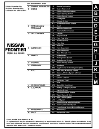
  • 1. -1 QUICK REFERENCE INDEX A GENERAL INFORMATION GI General Information B ENGINE EM Engine Mechanical LU Engine Lubrication System CO Engine Cooling System EC Engine Control System FL Fuel System EX Exhaust System ACC Accelerator Control System C TRANSMISSION/ TRANSAXLE CL Clutch MT Manual Transmission AT Automatic Transmission D DRIVELINE/AXLE TF Transfer PR Propeller Shaft FFD Front Final Drive RFD Rear Final Drive FAX Front Axle RAX Rear Axle E SUSPENSION FSU Front Suspension RSU Rear Suspension WT Road Wheels & Tires F BRAKES BR Brake System PB Parking Brake System BRC Brake Control System G STEERING PS Power Steering System H RESTRAINTS SB Seat Belts SRS Supplemental Restraint System (SRS) I BODY BL Body, Lock & Security System GW Glasses, Window System & Mirrors RF Roof EI Exterior & Interior IP Instrument Panel SE Seat J AIR CONDITIONER MTC Manual Air Conditioner K ELECTRICAL SC Starting & Charging System LT Lighting System DI Driver Information System WW Wiper, Washer & Horn BCS Body Control System LAN LAN System AV Audio Visual & Telephone System ACS Auto Cruise Control System PG Power Supply, Ground & Circuit Elements L MAINTENANCE MA Maintenance M INDEX IDX Alphabetical Index Edition: November 2004 Revision: November 2005 Publication No. SM5E-1D40U2 B D © 2005 NISSAN NORTH AMERICA, INC. All rights reserved. No part of this Service Manual may be reproduced or stored in a retrieval system, or transmitted in any form, or by any means, electronic, mechanical, photo-copying, recording or otherwise, without the prior written permission of Nissan North America, Inc., Gardena, California. A C E F G H I J K L M
  • 2. -2 This manual contains maintenance and repair procedures for the 2005 NISSAN FRONTIER. In order to assure your safety and the efficient functioning of the vehicle, this manual should be read thoroughly. It is especially important that the PRECAUTIONS in the GI section be completely understood before starting any repair task. All information in this manual is based on the latest product information at the time of publication. The right is reserved to make changes in specifi- cations and methods at any time without notice. IMPORTANT SAFETY NOTICE The proper performance of service is essential for both the safety of the technician and the efficient functioning of the vehicle. The service methods in this Service Manual are described in such a manner that the service may be performed safely and accurately. Service varies with the procedures used, the skills of the technician and the tools and parts available. Accordingly, anyone using service procedures, tools or parts which are not specifically recommended by NISSAN must first be completely satisfied that neither personal safety nor the vehicle’s safety will be jeopardized by the service method selected.
  • 3. QUICK REFERENCE CHART; FRONTIER 2005 QUICK REFERENCE CHART; FRONTIER PFP:00000 Engine Tune-Up Data ELS001KR QR Engine Specifications VQ Engine Specifications Cylinder arrangement In-line 4 Displacement 2,488 cm3 (151.82 in3 ) Bore and stroke 89.0 x 100.0 mm (3.504 x 3.937 in) Valve arrangement DOHC Firing order 1-3-4-2 Number of piston rings Compression 2 Oil 1 Compression ratio 9.5:1 Compression pressure Standard 1,304 kPa (13.3 kg/cm2 , 189 psi) / 250 rpm Minimum 1,108 kPa (11.3 kg/cm2 , 161 psi) / 250 rpm Differential limit between cylinders 100 kPa (1.0 kg/cm2 , 14 psi) / 250 rpm Valve timing Unit: degree a b c d e f 236° 224° -4° 60° 32° 37° Cylinder arrangement V-6 Displacement 3,954 cm3 (241.30 in3 ) Bore and stroke 95.5 × 92.0 mm (3.76 × 3.622 in) Valve arrangement DOHC Firing order 1-2-3-4-5-6 Number of piston rings Compression 2 Oil 1 Number of main bearings 4 Compression ratio 9.7:1 Compression pressure Standard 1,275 kPa (13.0 kg/cm2 , 185 psi) / 300 rpm Minimum 981 kPa (10.0 kg/cm2 , 142 psi) / 300 rpm Differential limit between cylinders 98 kPa (1.0 kg/cm2 , 14 psi) / 300 rpm PBIC0187E
  • 4. 2005 QUICK REFERENCE CHART; FRONTIER QR and VQ Engine Drive Belt Deflection and Tension QR Engine Spark Plugs (Double Platinum Tipped) VQ Engine Spark Plugs (Double Platinum Tipped) Wheel Alignment (Unladen*1 )*6 ELS001KS Cylinder number Valve timing (Intake valve timing control - “OFF”) Unit: degree a b c d e f 244° 240° −4° 64° 6° 58° Tension of drive belt Auto adjustment by auto-tensioner Make NGK Standard type PLZKAR6A-11 Hot type PLZKAR5A-11 Cold type PLZKAR7A-11 Gap (nominal) 1.1 mm (0.043 in) Make NGK Standard type PLFR5A-11 Hot type PLFR4A-11 Cold type PLFR6A-11 Gap (nominal) 1.1 mm (0.043 in) SEM713A PBIC0187E Drive type 2WD 4WD Camber Degree minute (decimal degree) Minimum -0° 30′ (-0.50°) -0° 15′ (-0.25°) Nominal 0° 15′ (0.25°) 0° 30′ (0.50°) Maximum 1° 00′ (1.00°) 1° 15′ (1.25°) Cross camber 0° 45′ (0.75°) or less 0° 45′ (0.75°) or less
  • 5. QUICK REFERENCE CHART; FRONTIER 2005 *1: Fuel, radiator coolant and engine oil full. Spare tire, jack, hand tools and mats in designated positions. *2: Target value 35° 26′ (35.43°) *3: Target value 31° 22′ (31.37°) *4: Target value 35° 36′ (35.60°) *5: Target value 31° 44′ (31.73°) *6: Some vehicles may be equipped with straight (non-adjustable) lower link bolts and washers. In order to adjust camber and caster on these vehicles, first replace the lower link bolts and washers with adjustable (cam) bolts and washers. Brake ELS001KU Unit: mm (in) Caster Degree minute (decimal degree) Minimum 2° 15′ (2.25°) 2° 00′ (2.00°) Nominal 3° 0′ (3.00°) 2° 45′ (2.75°) Maximum 3° 45′ (3.75°) 3° 30′ (3.50°) Cross caster 0° 45′ (0.75°) or less 0° 45′ (0.75°) or less Kingpin inclination Degree minute (decimal degree) Nominal 13° 0′ (13.00°) 12° 45′ (12.75°) Total toe-in Distance (A − B) 2.1 mm (0.08 in) 2.1 mm (0.08 in) 3.1 mm (0.12 in) 3.1 mm (0.12 in) 4.1 mm (0.16 in) 4.1 mm (0.16 in) Angle (left wheel or right wheel) Degree minute (decimal degree) 0° 5′ (0.08°) 0° 5′ (0.08°) 0° 7′ (0.12°) 0° 7′ (0.12°) 0° 9′ (0.15°) 0° 9′ (0.15°) Wheel turning angle (full turn) Inside Degree minute (decimal degree) 33° 26′ – 35° 26′ *2 (33.43° – 35.43°) 33° 36′ – 35° 36′ *4 (33.60° – 35.60°) Outside Degree minute (decimal degree) 29° 22′ – 31° 22′ *3 (29.37° – 31.37°) 29° 44′ – 31° 44′ *5 (29.73° – 31.73°) Drive type 2WD 4WD SFA234AC Engine QR25DE VQ40DE Front brake Brake model CLZ33VA Rotor outer diameter × thickness 296 × 28 (11.65 × 1.10) Pad Length × width × thickness 140 × 49 × 10 (5.51 × 1.93 × 0.39) Cylinder bore diameter (Dual pis- ton) 46.4 (1.83) Rear brake Brake model CLZ11VA Rotor outer diameter × thickness 286 × 18 (11.26 × 0.71) Pad Length × width × thickness 87.6 × 35 × 11 (3.45 × 1.38 × 0.43) Cylinder bore diameter (Single pis- ton) 38.1 (1.50) Control valve Valve model EBD
  • 6. 2005 QUICK REFERENCE CHART; FRONTIER Disc Brake - Repair Limits ELS001KV FRONT DISC BRAKE Unit: mm (in) REAR DISC BRAKE Unit: mm (in) Brake Pedal ELS001KW Unit: mm (in) Brake booster Booster model C215T Diaphragm diameter 215 (8.46) Recommended brake fluid Genuine NISSAN Super Heavy Duty Brake Fluid or equivalent DOT 3 (US FMVSS No. 116) Brake model CLZ33VA Brake pad Standard thickness (new) 10 (0.394) Repair limit thickness 2 (0.079) Disc rotor Standard thickness (new) 28 (1.10) Repair limit thickness 26 (1.024) Maximum uneven wear (measured at 8 positions) 0.015 (0.0006) Runout limit (with it attached to the vehicle) 0.05 (0.0020) Brake model CLZ11VA Brake pad Standard thickness (new) 11 (0.433) Repair limit thickness 2 (0.079) Disc rotor Standard thickness (new) 18 (0.709) Repair limit thickness 16 (0.630) Maximum uneven wear (measured at 8 positions) 0.015 (0.0006) Runout limit (with it attached to the vehicle) 0.05 (0.0020) Free height "H" A/T 182.1 - 192.1 (7.17 - 7.56) M/T 174.7 - 184.7 (6.88 - 7.27) WFIA0160E
  • 7. QUICK REFERENCE CHART; FRONTIER 2005 Refill Capacities ELS001KX QR Engine VQ Engine Depressed pedal height ("D" [under a force of 490 N (50 kg, 110 lb) with engine running] 103 - 123 (4.06 - 4.84) Clearance between pedal stopper and threaded end of stop lamp switch and ASCD switch "C1 " or “C2 ” 0.74 - 1.96 (0.029 - 0.077) Pedal play "A" 3 - 11 (0.12 - 0.43) Description Capacity (Approximate) Metric US measure Imp measure Fuel 80 21 1/8 gal 17 5/8 gal Engine oil Drain and refill With oil filter change 4.9 5 1/8 qt 4 3/8 qt Without oil filter change 4.6 4 7/8 qt 4 qt Dry engine (engine overhaul) 5.0 5 1/4 qt 4 3/8 qt Cooling system With reservoir at MAX level 9.4 2 1/2 gal 2 1/8 gal Automatic transmission fluid (ATF) 10.3 10 7/8 qt 9 1/8 qt Manual transmission fluid (MTF) (5 M/T model) 2.89 3 qt 2 1/2 qt Rear final drive oil C200 1.6 3 3/8 pt 2 7/8 pt Power steering fluid (PSF) 1.0 2 1/8 pt 1 3/4 pt Windshield washer fluid 4.5 1 1/4 gal 1 gal Air conditioning system refrigerant 0.70 ± 0.05 kg 1.54 ± 0.11 lb 1.54 ± 0.11 lb Air conditioning system lubricant 180 m 6.1 fl oz 6.3 fl oz Description Capacity (Approximate) Metric US measure Imp measure Fuel 80 21 1/8 gal 17 5/8 gal Engine oil Drain and refill With oil filter change 5.1 5 3/8 qt 4 1/2 qt Without oil filter change 4.8 5 1/8 qt 4 1/4 qt Dry engine (engine overhaul) 6.3 6 5/8 qt 5 1/2 qt Cooling system With reservoir at MAX level 10.2 2 3/4 gal 2 1/4 gal Automatic transmission fluid (ATF) 10.3 10 7/8 qt 9 1/8 qt Manual transmission fluid (MTF) (6 M/T model) 2WD 3.98 4 1/4 qt 3 1/2 qt 4WD 4.18 4 3/8 qt 3 5/8 qt Rear final drive oil C200 1.6 3 3/8 pt 2 7/8 pt M226 2.01 4 1/4 pt 3 1/2 pt Transfer fluid TX15B 2.0 2 1/8 qt 1 3/4 qt Front final drive oil 0.85 1 3/4 pt 1 1/2 pt Power steering fluid (PSF) 1.0 2 1/8 pt 1 3/4 pt Windshield washer fluid 4.5 1 1/4 gal 1 gal A/C system refrigerant 0.70 ± 0.05 kg 1.54 ± 0.11 lb 1.54 ± 0.11 lb A/C system lubricant 180 m 6.1 fl oz 6.3 fl oz
  • 8. GI-1 GENERAL INFORMATION A GENERAL INFORMATION CONTENTS C D E F G H I J K L M B GI SECTION GI Revision: November 2005 2005 Frontier PRECAUTIONS ..................................................... ..... 3 Description .......................................................... ..... 3 Precautions for Supplemental Restraint System (SRS) “AIR BAG” and “SEAT BELT PRE-TEN- SIONER” ............................................................. ..... 3 Precautions for NVIS/IVIS (NISSAN/INFINITI VEHICLE IMMOBILIZER SYSTEM - NATS) (If Equipped) ............................................................ ..... 3 General Precautions ........................................... ..... 4 Precautions for Three Way Catalyst .................... ..... 5 Precautions for Fuel ............................................ ..... 5 QR25DE MODELS ........................................... ..... 5 VQ40DE MODELS ........................................... ..... 5 Precautions for Multiport Fuel Injection System or Engine Control System ....................................... ..... 6 Precautions for Hoses ......................................... ..... 6 HOSE REMOVAL AND INSTALLATION .......... ..... 6 HOSE CLAMPING ........................................... ..... 7 Precautions for Engine Oils ................................. ..... 7 HEALTH PROTECTION PRECAUTIONS ........ ..... 7 ENVIRONMENTAL PROTECTION PRECAU- TIONS .............................................................. ..... 7 Precautions for Air Conditioning .......................... ..... 8 HOW TO USE THIS MANUAL .............................. ..... 9 Description .......................................................... ..... 9 Terms .................................................................. ..... 9 Units .................................................................... ..... 9 Contents .............................................................. ..... 9 Relation between Illustrations and Descriptions . ... 10 Components ........................................................ ... 10 SYMBOLS ........................................................ ....11 How to Follow Trouble Diagnoses ....................... ....11 DESCRIPTION ................................................. ... 12 HOW TO FOLLOW TEST GROUPS IN TROU- BLE DIAGNOSES ............................................ ... 13 HARNESS WIRE COLOR AND CONNECTOR NUMBER INDICATION .................................... ... 13 KEY TO SYMBOLS SIGNIFYING MEASURE- MENTS OR PROCEDURES ............................ ... 15 How to Read Wiring Diagrams ............................ ... 17 CONNECTOR SYMBOLS ................................ ... 17 SAMPLE/WIRING DIAGRAM - EXAMPL - ....... ... 18 DESCRIPTION ................................................. ... 19 Abbreviations ....................................................... ... 24 SERVICE INFORMATION FOR ELECTRICALINCI- DENT ...................................................................... ... 26 How to Check Terminal ........................................ ... 26 CONNECTOR AND TERMINAL PIN KIT ......... ... 26 HOW TO PROBE CONNECTORS ................... ... 26 How to Perform Efficient Diagnosis for an Electrical Incident ................................................................ ... 29 WORK FLOW ................................................... ... 29 INCIDENT SIMULATION TESTS ..................... ... 29 CIRCUIT INSPECTION .................................... ... 32 Control Units and Electrical Parts ........................ ... 37 PRECAUTIONS ............................................... ... 37 SMJ INSTALLATION ........................................ ... 38 CONSULT-II CHECKING SYSTEM ....................... ... 39 Description ........................................................... ... 39 Function and System Application ........................ ... 39 Nickel Metal Hydride Battery Replacement ......... ... 39 Checking Equipment ........................................... ... 39 CONSULT-II Start Procedure ............................... ... 40 CONSULT-II Data Link Connector (DLC) Circuit . ... 40 INSPECTION PROCEDURE ........................... ... 40 LIFTING POINT ...................................................... ... 42 Pantograph Jack .................................................. ... 42 Garage Jack and Safety Stand ............................ ... 42 2-Pole Lift ............................................................ ... 43 TOW TRUCK TOWING .......................................... ... 44 Tow Truck Towing ................................................ ... 44 2WD MODEL .................................................... ... 44 4WD MODEL .................................................... ... 45 Vehicle Recovery (Freeing a stuck vehicle) ......... ... 45 TIGHTENING TORQUE OF STANDARD BOLTS . ... 46 Tightening Torque Table ...................................... ... 46 RECOMMENDED CHEMICAL PRODUCTS AND SEALANTS ............................................................ ... 47 Recommended Chemical Products and Sealants... 47 IDENTIFICATION INFORMATION ......................... ... 48
  • 9. Thank you very much for your reading. Please Click Here Then Get More Information. NOTE: If there is no response to click on the link above, please download the PDF document first and then click on it.
  • 10. PRECAUTIONS GI-3 C D E F G H I J K L M B GI Revision: November 2005 2005 Frontier PRECAUTIONS PFP:00001 Description EAS001G7 Observe the following precautions to ensure safe and proper servicing. These precautions are not described in each individual section. Precautions for Supplemental Restraint System (SRS) “AIR BAG” and “SEAT BELT PRE-TENSIONER” EAS001G8 The Supplemental Restraint System such as “AIR BAG” and “SEAT BELT PRE-TENSIONER”, used along with a front seat belt, helps to reduce the risk or severity of injury to the driver and front passenger for certain types of collision. This system includes seat belt switch inputs and dual stage front air bag modules. The SRS system uses the seat belt switches to determine the front air bag deployment, and may only deploy one front air bag, depending on the severity of a collision and whether the front occupants are belted or unbelted. Information necessary to service the system safely is included in the SRS and SB section of this Service Man- ual. WARNING: ● To avoid rendering the SRS inoperative, which could increase the risk of personal injury or death in the event of a collision which would result in air bag inflation, all maintenance must be per- formed by an authorized NISSAN/INFINITI dealer. ● Improper maintenance, including incorrect removal and installation of the SRS, can lead to per- sonal injury caused by unintentional activation of the system. For removal of Spiral Cable and Air Bag Module, see the SRS section. ● Do not use electrical test equipment on any circuit related to the SRS unless instructed to in this Service Manual. SRS wiring harnesses can be identified by yellow and/or orange harnesses or harness connectors. Precautions for NVIS/IVIS (NISSAN/INFINITI VEHICLE IMMOBILIZER SYSTEM - NATS) (If Equipped) EAS001YS NVIS/IVIS (NATS) will immobilize the engine if someone tries to start it without the registered key of NVIS/IVIS (NATS). Both of the originally supplied ignition key IDs have been NVIS/IVIS (NATS) registered. The security indicator is located on the instrument panel. The indicator blinks when the immobilizer system is functioning. Therefore, NVIS/IVIS (NATS) warns outsiders that the vehicle is equipped with the anti-theft system. ● When NVIS/IVIS (NATS) detects trouble, the security indicator lamp lights up while ignition switch is in "ON" position. This lighting up indicates that the anti-theft is not functioning, so prompt service is required. ● When servicing NVIS/IVIS (NATS) (trouble diagnoses, system initialization and additional registration of other NVIS/IVIS (NATS) ignition key IDs), CONSULT-II hardware and CONSULT-II NVIS/IVIS (NATS) software is necessary. Regarding the procedures of NVIS/IVIS (NATS) initialization and NVIS/IVIS (NATS) ignition key ID regis- tration, refer to CONSULT-II operation manual, NVIS/IVIS (NATS). Therefore, CONSULT-II NVIS/IVIS (NATS) software (program card and operation manual) must be kept strictly confidential to maintain the integrity of the anti-theft function. ● When servicing NVIS/IVIS (NATS) (trouble diagnoses, system initialization and additional registration of other NVIS/IVIS (NATS) ignition key IDs), it may be necessary to re-register original key identification. Therefore, be sure to receive all keys from vehicle owner. A maximum of four or five key IDs can be regis- tered into NVIS/IVIS (NATS). ● When failing to start the engine first time using the key of NVIS/IVIS (NATS), start as follows. 1. Leave the ignition key in "ON" position for approximately 5 seconds. 2. Turn ignition key to "OFF" or "LOCK" position and wait approximately 5 seconds. 3. Repeat step 1 and 2 again. 4. Restart the engine while keeping the key separate from any others on key-chain.
  • 11. GI-4 PRECAUTIONS Revision: November 2005 2005 Frontier General Precautions EAS001G9 ● Do not operate the engine for an extended period of time without proper exhaust ventilation. Keep the work area well ventilated and free of any inflammable materials. Special care should be taken when handling any inflammable or poisonous materials, such as gasoline, refriger- ant gas, etc. When working in a pit or other enclosed area, be sure to properly ventilate the area before working with hazard- ous materials. Do not smoke while working on the vehicle. ● Before jacking up the vehicle, apply wheel chocks or other tire blocks to the wheels to prevent the vehicle from moving. After jacking up the vehicle, support the vehicle weight with safety stands at the points designated for proper lifting before working on the vehicle. These operations should be done on a level surface. ● When removing a heavy component such as the engine or tran- saxle/transmission, be careful not to lose your balance and drop them. Also, do not allow them to strike adjacent parts, especially the brake tubes and master cylinder. ● Before starting repairs which do not require battery power: Turn off ignition switch. Disconnect the negative battery terminal. ● If the battery terminals are disconnected, recorded memory of radio and each control unit is erased. ● To prevent serious burns: Avoid contact with hot metal parts. Do not remove the radiator cap when the engine is hot. ● Dispose of drained oil or the solvent used for cleaning parts in an appropriate manner. ● Do not attempt to top off the fuel tank after the fuel pump nozzle shuts off automatically. Continued refueling may cause fuel overflow, resulting in fuel spray and possibly a fire. ● Clean all disassembled parts in the designated liquid or solvent prior to inspection or assembly. ● Replace oil seals, gaskets, packings, O-rings, locking washers, cotter pins, self-locking nuts, etc. with new ones. ● Replace inner and outer races of tapered roller bearings and needle bearings as a set. ● Arrange the disassembled parts in accordance with their assembled locations and sequence. ● Do not touch the terminals of electrical components which use microcomputers (such as ECM). Static electricity may damage internal electronic components. ● After disconnecting vacuum or air hoses, attach a tag to indicate the proper connection. ● Use only the fluids and lubricants specified in this manual. SGI285 SGI231 SEF289H SGI233
  • 12. PRECAUTIONS GI-5 C D E F G H I J K L M B GI Revision: November 2005 2005 Frontier ● Use approved bonding agent, sealants or their equivalents when required. ● Use hand tools, power tools (disassembly only) and recom- mended special tools where specified for safe and efficient ser- vice repairs. ● When repairing the fuel, oil, water, vacuum or exhaust systems, check all affected lines for leaks. ● Before servicing the vehicle: Protect fenders, upholstery and carpeting with appropriate cov- ers. Take caution that keys, buckles or buttons do not scratch paint. WARNING: To prevent ECM from storing the diagnostic trouble codes, do not carelessly disconnect the harness connectors which are related to the engine control system and TCM (transmission control module) system. The connectors should be disconnected only when working according to the WORK FLOW of TROUBLE DIAGNOSES in EC and AT sections. Precautions for Three Way Catalyst EAS001GA If a large amount of unburned fuel flows into the catalyst, the catalyst temperature will be excessively high. To prevent this, follow the instructions. ● Use unleaded gasoline only. Leaded gasoline will seriously damage the three way catalyst. ● When checking for ignition spark or measuring engine compression, make tests quickly and only when necessary. ● Do not run engine when the fuel tank level is low, otherwise the engine may misfire, causing damage to the catalyst. Do not place the vehicle on flammable material. Keep flammable material off the exhaust pipe and the three way catalyst. Precautions for Fuel EAS001MP QR25DE MODELS Use unleaded regular gasoline with an octane rating of at least 87 AKI (Anti-Knock Index) number (Research octane number 91). E-85 fuel (85% fuel ethanol, 15% unleaded gasoline) may only be used in vehicles specif- ically designed for E-85 fuel (i.e. Flexible Fuel Vehicles - FFV models). CAUTION: Do not use leaded gasoline. Using leaded gasoline will damage the three way catalyst. Do not use E-85 fuel (85% fuel ethanol, 15% unleaded gasoline) unless the vehicle is specifically designed for E-85 fuel (i.e. Flexible Fuel Vehicle - FFV models). Using a fuel other than that specified could adversely affect the emission control devices and systems, and could also affect the warranty coverage validity. VQ40DE MODELS Use unleaded regular gasoline with an octane rating of at least 87 AKI (Anti-Knock Index) number (Research octane number 91). E-85 fuel (85% fuel ethanol, 15% unleaded gasoline) may only be used in vehicles specif- ically designed for E-85 fuel (i.e. Flexible Fuel Vehicles - FFV models). PBIC0190E SGI234
  • 13. GI-6 PRECAUTIONS Revision: November 2005 2005 Frontier For improved vehicle performance, NISSAN/INFINITI recommend the use of unleaded premium gasoline with an octane rating of at least 91 AKI number (Research octane number 96). CAUTION: Do not use leaded gasoline. Using leaded gasoline will damage the three way catalyst. Do not use E-85 fuel (85% fuel ethanol, 15% unleaded gasoline) unless the vehicle is specifically designed for E-85 fuel (i.e. Flexible Fuel Vehicle - FFV models). Using a fuel other than that specified could adversely affect the emission control devices and systems, and could also affect the warranty coverage validity. Precautions for Multiport Fuel Injection System or Engine Control System EAS001GC ● Before connecting or disconnecting any harness connector for the multiport fuel injection system or ECM: Turn ignition switch to “OFF” position. Disconnect negative battery terminal. Otherwise, there may be damage to ECM. ● Before disconnecting pressurized fuel line from fuel pump to injectors, be sure to release fuel pressure. ● Be careful not to jar components such as ECM and mass air flow sensor. Precautions for Hoses EAS001GD HOSE REMOVAL AND INSTALLATION ● To prevent damage to rubber hose, do not pry off rubber hose with tapered tool or screwdriver. ● To reinstall the rubber hose securely, make sure of hose inser- tion length and clamp orientation. (If tube is equipped with hose stopper, insert rubber hose into tube until it butts up against hose stopper.) SGI787 SMA019D SMA020D