
Recommended
Recommended
More Related Content
What's hot
Similar to 2001 Nissan Pathfinder Service Repair Manual
Similar to 2001 Nissan Pathfinder Service Repair Manual (9)
Recently uploaded
Recently uploaded (20)
2001 Nissan Pathfinder Service Repair Manual
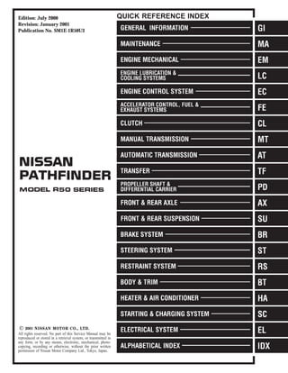
- 1. Edition: July 2000 Revision: January 2001 Publication No. SM1E-1R50U3 QUICK REFERENCE INDEX All rights reserved. No part of this Service Manual may be reproduced or stored in a retrieval system, or transmitted in any form, or by any means, electronic, mechanical, photo- copying, recording or otherwise, without the prior written permission of Nissan Motor Company Ltd., Tokyo, Japan.
- 2. FOREWORD This manual contains maintenance and repair procedures for the 2001 Nissan PATHFINDER. In order to assure your safety and the efficient functioning of the vehicle, this manual should be read thoroughly. It is especially important that the PRECAUTIONS in the GI section be completely understood before starting any repair task. All information in this manual is based on the latest product infor- mation at the time of publication. The right is reserved to make changes in specifications and methods at any time without notice. IMPORTANT SAFETY NOTICE The proper performance of service is essential for both the safety of the technician and the efficient functioning of the vehicle. The service methods in this Service Manual are described in such a manner that the service may be performed safely and accurately. Service varies with the procedures used, the skills of the technician and the tools and parts available. Accordingly, anyone using service procedures, tools or parts which are not specifically recommended by NISSAN must first be completely satisfied that neither parsonal safety nor the vehicle’s safety will be jeopardized by the service method selected.
- 3. Attachment No.22 TID CID P0420 01H 01H Max. 1/128 P0420 02H 81H Min. 1 P0430 03H 02H Max. 1/128 P0430 04H 82H Min. 1 P0440 05H 03H Max. 1/128mm2 P1440 05H 03H Max. 1/128mm2 EVAP control system purge flow monitoring P1447 06H 83H Min. 20mV EVAP control system (Very small leak) P1441 07H 03H Max. 1/128mm2 P0133 09H 04H Max. 16ms P0131 0AH 84H Min. 10mV P0130 0BH 04H Max. 10mV P0132 0CH 04H Max. 10mV P0134 0DH 04H Max. 1s P0153 11H 05H Max. 16ms P0151 12H 85H Min. 10mV P0150 13H 05H Max. 10mV P0152 14H 05H Max. 10mV P0154 15H 05H Max. 1s P0139 19H 86H Min. 10mV/500ms P0137 1AH 86H Min. 10mV P0140 1BH 06H Max. 10mV P0138 1CH 06H Max. 10mV P0159 21H 87H Min. 10mV/500ms P0157 22H 87H Min. 10mV P0160 23H 07H Max. 10mV P0158 24H 07H Max. 10mV P0135 29H 08H Max. 20mV P0135 2AH 88H Min. 20mV P0155 2BH 09H Max. 20mV P0155 2CH 89H Min. 20mV P0141 2DH 0AH Max. 20mV P0141 2EH 8AH Min. 20mV P0161 2FH 0BH Max. 20mV P0161 30H 8BH Min. 20mV TEST VALUE AND TEST LIMIT (GST ONLY — NOT APPLICABLE TO CONSULT-II) Items for which these data (test value and test limit) are displayed are the same as SRT code items. These data (test value and test limit) are specified by Test ID (TID) and Component ID (CID) and can be dis- played on the GST screen. The following is the information specified in Mode 6 of SAE J1979. The test value is a parameter used to determine whether a system/circuit diagnostic test is “OK” or “NG” while being monitored by the ECM during self-diagnosis. The test limit is a reference value which is specified as the maximum or minimum value and is compared with the test value being monitored. Test limit Conversion CATALYST Three way catalyst function (Bank 1) Three way catalyst function (Bank 2) SRT item Self-diagnostic test item DTC Test value (GST display) EVAP SYSTEM EVAP control system (Small leak) HO2S Heated oxygen sensor 1 (Bank 1) Heated oxygen sensor 1 (Bank 2) Heated oxygen sensor 2 (Bank 1) Heated oxygen sensor 2 (Bank 2) HO2S HTR Heated oxygen sensor 1 heater (Bank 1) Heated oxygen sensor 1 heater (Bank 2) Heated oxygen sensor 2 heater (Bank 1) Heated oxygen sensor 2 heater (Bank 2)
- 4. GENERAL INFORMATION SECTION GI CONTENTS PRECAUTIONS ...............................................................3 Precautions..................................................................3 PRECAUTIONS FOR SUPPLEMENTAL RESTRAINT SYSTEM (SRS) ″AIR BAG″ AND ″SEAT BELT PRE-TENSIONER″ .................................3 PRECAUTIONS FOR NVIS (NISSAN VEHICLE IMMOBILIZER SYSTEM - NATS).................................3 GENERAL PRECAUTIONS.........................................4 PRECAUTIONS FOR MULTIPORT FUEL INJECTION SYSTEM OR ENGINE CONTROL SYSTEM ...................................................................6 PRECAUTIONS FOR THREE WAY CATALYST ...........6 PRECAUTIONS FOR HOSES.....................................7 PRECAUTIONS FOR ENGINE OILS ...........................7 PRECAUTIONS FOR FUEL........................................8 PRECAUTIONS FOR AIR CONDITIONING ..................8 HOW TO USE THIS MANUAL........................................9 HOW TO READ WIRING DIAGRAMS..........................11 Sample/Wiring Diagram - EXAMPL - ........................11 OPTIONAL SPLICE..................................................12 Description.................................................................13 CONNECTOR SYMBOLS .........................................15 HARNESS INDICATION ...........................................16 COMPONENT INDICATION......................................16 SWITCH POSITIONS ...............................................16 DETECTABLE LINES AND NON-DETECTABLE LINES .....................................................................17 MULTIPLE SWITCH.................................................18 REFERENCE AREA.................................................19 HOW TO CHECK TERMINAL.......................................21 Connector and Terminal Pin Kit.................................21 How to Probe Connectors .........................................21 PROBING FROM HARNESS SIDE............................21 PROBING FROM TERMINAL SIDE ...........................21 How to Check Enlarged Contact Spring of Terminal .....................................................................22 Waterproof Connector Inspection..............................23 RUBBER SEAL INSPECTION...................................23 WIRE SEAL INSPECTION........................................23 Terminal Lock Inspection...........................................23 HOW TO PERFORM EFFICIENT DIAGNOSIS FOR AN ELECTRICAL INCIDENT ...............................24 Work Flow..................................................................24 Incident Simulation Tests...........................................25 INTRODUCTION......................................................25 VEHICLE VIBRATION ..............................................25 HEAT SENSITIVE....................................................26 FREEZING ..............................................................26 WATER INTRUSION ................................................27 ELECTRICAL LOAD.................................................27 COLD OR HOT START UP.......................................27 Circuit Inspection .......................................................27 INTRODUCTION......................................................27 TESTING FOR ″OPENS″ IN THE CIRCUIT ................28 TESTING FOR ″SHORTS″ IN THE CIRCUIT..............29 GROUND INSPECTION ...........................................30 VOLTAGE DROP TESTS..........................................30 CONTROL UNIT CIRCUIT TEST ...............................32 HOW TO FOLLOW TROUBLE DIAGNOSES...............34 How to Follow Test Groups in Trouble Diagnoses....35 Harness Wire Color and Connector Number Indication....................................................................36 TYPE 1: HARNESS WIRE COLOR AND CONNECTOR NUMBER ARE SHOWN IN ILLUSTRATION .......................................................36 TYPE 2: HARNESS WIRE COLOR AND CONNECTOR NUMBER ARE SHOWN IN TEXT ........36 Key to Symbols Signifying Measurements or Procedures.................................................................37 CONSULT-II CHECKING SYSTEM...............................39 Function and System Application ..............................39 Nickel Metal Hydride Battery Replacement...............40 Checking Equipment..................................................40 CONSULT-II Data Link Connector (DLC) Circuit ......40 INSPECTION PROCEDURE .....................................40 IDENTIFICATION INFORMATION ................................42 Model Variation..........................................................42 2WD .......................................................................42 4WD .......................................................................42 PREFIX AND SUFFIX DESIGNATIONS .....................42 MA EM LC EC FE CL MT AT TF PD AX SU BR ST RS BT HA SC EL IDX
- 5. Identification Number.................................................43 VEHICLE IDENTIFICATION NUMBER ARRANGEMENT .....................................................43 IDENTIFICATION PLATE..........................................44 ENGINE SERIAL NUMBER.......................................44 MANUAL TRANSMISSION NUMBER.........................44 AUTOMATIC TRANSMISSION NUMBER ...................44 TRANSFER SERIAL NUMBER..................................45 Dimensions ................................................................45 Wheels & Tires ..........................................................45 LIFTING POINTS AND TOW TRUCK TOWING ...........46 Screw Jack ................................................................46 Garage Jack and Safety Stand .................................47 2-pole Lift...................................................................48 Tow Truck Towing ......................................................48 2WD MODELS.........................................................49 PART TIME 4WD MODELS ......................................49 ALL-MODE 4WD MODELS .......................................50 VEHICLE RECOVERY..............................................50 TIGHTENING TORQUE OF STANDARD BOLTS ........51 SAE J1930 TERMINOLOGY LIST ................................52 SAE J1930 Terminology List .....................................52 CONTENTS (Cont’d) GI-2
- 6. Precautions NAGI0001 Observe the following precautions to ensure safe and proper servicing. These precautions are not described in each indi- vidual section. SGI646 PRECAUTIONS FOR SUPPLEMENTAL RESTRAINT SYSTEM (SRS) “AIR BAG” AND “SEAT BELT PRE-TENSIONER” NAGI0001S01 The Supplemental Restraint System such as “AIR BAG” and “SEAT BELT PRE-TENSIONER” used along with a seat belt, helps to reduce the risk or severity of injury to the driver and front passen- ger for certain types of collision. The SRS system composition which is available to NISSAN MODEL R50 is as follows: ¼ For a frontal collision The Supplemental Restraint System consists of driver air bag module (located in the center of the steering wheel), front pas- senger air bag module (located on the instrument panel on passenger side), seat belt pre-tensioners, a diagnosis sensor unit, warning lamp, wiring harness and spiral cable. ¼ For a side collision The Supplemental Restraint System consists of side air bag module (located in the outer side of front seat), satellite sensor, diagnosis sensor unit (one of components of air bags for a frontal collision), wiring harness, warning lamp (one of compo- nents of air bags for a frontal collision). Information necessary to service the system safely is included in the RS section of this Service Manual. WARNING: ¼ To avoid rendering the SRS inoperative, which could increase the risk of personal injury or death in the event of a collision which would result in air bag inflation, all maintenance must be performed by an authorized NISSAN dealer. ¼ Improper maintenance, including incorrect removal and installation of the SRS, can lead to personal injury caused by unintentional activation of the system. For removal of Spiral Cable and Air Bag Module, see the RS section. ¼ Do not use electrical test equipment on any circuit related to the SRS unless instructed to in this Service Manual. SRS wiring harnesses can be identified with yellow har- ness connector (and with yellow harness protector or yel- low insulation tape before the harness connectors). PRECAUTIONS FOR NVIS (NISSAN VEHICLE IMMOBILIZER SYSTEM — NATS) NAGI0001S08 NVIS (NATS) will immobilize the engine if someone tries to start it without the registered key of NVIS (NATS). Both of the originally supplied ignition key IDs have been NVIS (NATS) registered. MA EM LC EC FE CL MT AT TF PD AX SU BR ST RS BT HA SC EL IDX PRECAUTIONS Precautions GI-3
- 7. The security indicator is located on the instrument panel. The indi- cator blinks when the ignition switch is in “OFF” or “ACC” position. Therefore, NVIS (NATS) warns outsiders that the vehicle is equipped with the anti-theft system. ¼ When NVIS (NATS) detects trouble, the security indicator lamp lights up while ignition switch is in “ON” position. This lighting up indicates that the anti-theft is not functioning, so prompt service is required. ¼ When servicing NVIS (NATS) (trouble diagnoses, system ini- tialization and additional registration of other NVIS (NATS) igni- tion key IDs), CONSULT-II hardware and CONSULT-II NVIS (NATS) software is necessary. Regarding the procedures of NVIS (NATS) initialization and NVIS (NATS) ignition key ID registration, refer to CONSULT-II operation manual, IVIS/NVIS. Therefore, CONSULT-II NVIS (NATS) software (program card and operation manual) must be kept strictly confidential to maintain the integrity of the anti-theft function. ¼ When servicing NVIS (NATS) (trouble diagnoses, system ini- tialization and additional registration of other NVIS (NATS) igni- tion key IDs), it may be necessary to re-register original key identification. Therefore, be sure to receive all keys from vehicle owner. A maximum of five key IDs can be registered into NVIS (NATS). ¼ When failing to start the engine first time using the key of NVIS (NATS) (for example, when interference is caused by another NVIS (NATS) key, an automated full road device or automated payment device on the key ring), restart as follows. a) Leave the ignition switch in “ON” position for approximately 5 seconds. b) Turn ignition switch to “OFF” or “LOCK” position and wait approximately 5 seconds. c) Repeat step 1 and 2. d) Restart the engine while holding the device (which may have caused the interference) separate from the registered NVIS (NATS) key. If the no start condition re-occurs, NISSAN rec- ommends placing the registered nats key on a separate key ring to avoid interference from other devices. SGI285 GENERAL PRECAUTIONS NAGI0001S02 ¼ Do not operate the engine for an extended period of time without proper exhaust ventilation. Keep the work area well ventilated and free of any inflammable materials. Special care should be taken when handling any inflammable or poisonous materials, such as gasoline, refrig- erant gas, etc. When working in a pit or other enclosed area, be sure to properly ventilate the area before working with haz- ardous materials. Do not smoke while working on the vehicle. PRECAUTIONS Precautions (Cont’d) GI-4
- 8. SGI231 ¼ Before jacking up the vehicle, apply wheel chocks or other tire blocks to the wheels to prevent the vehicle from moving. After jacking up the vehicle, support the vehicle weight with safety stands at the points designated for proper lifting before work- ing on the vehicle. These operations should be done on a level surface. ¼ When removing a heavy component such as the engine or transaxle/transmission, be careful not to lose your balance and drop it. Also, do not allow it to strike adjacent parts, especially the brake tubes and master cylinder. SEF289H ¼ Before starting repairs which do not require battery power: Turn off ignition switch. Disconnect the negative battery terminal. SGI233 ¼ To prevent serious burns: Avoid contact with hot metal parts. Do not remove the radiator cap when the engine is hot. SGI234 ¼ Before servicing the vehicle: Protect fenders, upholstery and carpeting with appropriate cov- ers. Take caution that keys, buckles or buttons do not scratch paint. ¼ Clean all disassembled parts in the designated liquid or solvent prior to inspection or assembly. ¼ Replace oil seals, gaskets, packings, O-rings, locking washers, cotter pins, self-locking nuts, etc. with new ones. ¼ Replace inner and outer races of tapered roller bearings and needle bearings as a set. ¼ Arrange the disassembled parts in accordance with their assembled locations and sequence. ¼ Do not touch the terminals of electrical components which use microcomputers (such as ECMs). Static electricity may damage internal electronic components. MA EM LC EC FE CL MT AT TF PD AX SU BR ST RS BT HA SC EL IDX PRECAUTIONS Precautions (Cont’d) GI-5
- 9. ¼ After disconnecting vacuum or air hoses, attach a tag to indi- cate the proper connection. ¼ Use only the fluids and lubricants specified in this manual. ¼ Use approved bonding agent, sealants or their equivalents when required. ¼ Use tools and recommended special tools where specified for safe and efficient service repairs. ¼ When repairing the fuel, oil, water, vacuum or exhaust systems, check all affected lines for leaks. ¼ Dispose of drained oil or the solvent used for cleaning parts in an appropriate manner. WARNING: To prevenvt ECM from storing the diagnostic trouble codes, do not carelessly disconnect the harness connectors which are related to the engine control system and TCM (Transmis- sion Control Module) system. The connectors should be dis- connected only when working according to the WORK FLOW of TROUBLE DIAGNOSES in EC and AT sections. SGI787 PRECAUTIONS FOR MULTIPORT FUEL INJECTION SYSTEM OR ENGINE CONTROL SYSTEM NAGI0001S03 ¼ Before connecting or disconnecting any harness connector for the multiport fuel injection system or ECM (Engine Control Module): Turn ignition switch to OFF position. Disconnect negative battery terminal. Otherwise, there may be damage to ECM. ¼ Before disconnecting pressurized fuel line from fuel pump to injectors, be sure to release fuel pressure. ¼ Be careful not to jar components such as ECM and mass air flow sensor. PRECAUTIONS FOR THREE WAY CATALYST NAGI0001S04 If a large amount of unburned fuel flows into the catalyst, the cata- lyst temperature will be excessively high. To prevent this, follow the instructions below: ¼ Use unleaded gasoline only. Leaded gasoline will seriously damage the three way catalyst. ¼ When checking for ignition spark or measuring engine compression, make tests quickly and only when necessary. ¼ Do not run engine when the fuel tank level is low, otherwise the engine may misfire causing damage to the catalyst. Do not place the vehicle on flammable material. Keep flammable material off the exhaust pipe and the three way catalyst. PRECAUTIONS Precautions (Cont’d) GI-6
- 10. SMA019D PRECAUTIONS FOR HOSES NAGI0001S10 Hose Removal and Installation NAGI0001S1001 ¼ To prevent damage to rubber hose, do not pry off rubber hose with tapered tool or screwdriver. SMA020D ¼ To reinstall the rubber hose securely, make sure of hose inser- tion length and clamp orientation. (If tube is equipped with hose stopper, insert rubber hose into tube until it butts up against hose stopper.) SMA021D Hose Clamping NAGI0001S1002 ¼ If old rubber hose is re-used, install hose clamp in its original position (at the indentation where the old clamp was). If there is a trace of tube bulging left on the old rubber hose, align rubber hose at that position. ¼ Discard old clamps; replace with new ones. SMA022D ¼ After installing leaf spring clamps, apply force to them in the direction of the arrow, tightening rubber hose equally all around. PRECAUTIONS FOR ENGINE OILS NAGI0001S05 Prolonged and repeated contact with used engine oil may cause skin cancer. Try to avoid direct skin contact with used oil. If skin contact is made, wash thoroughly with soap or hand cleaner as soon as possible. Health Protection Precautions NAGI0001S0501 ¼ Avoid prolonged and repeated contact with oils, particularly used engine oils. ¼ Wear protective clothing, including impervious gloves where practicable. MA EM LC EC FE CL MT AT TF PD AX SU BR ST RS BT HA SC EL IDX PRECAUTIONS Precautions (Cont’d) GI-7
- 11. ¼ Do not put oily rags in pockets. ¼ Avoid contaminating clothes, particularly underpants, with oil. ¼ Heavily soiled clothing and oil-impregnated footwear should not be worn. Overalls must be cleaned regularly. ¼ First Aid treatment should be obtained immediately for open cuts and wounds. ¼ Use barrier creams, applying them before each work period, to help the removal of oil from the skin. ¼ Wash with soap and water to ensure all oil is removed (skin cleansers and nail brushes will help). Preparations containing lanolin replace the natural skin oils which have been removed. ¼ Do not use gasoline, kerosine, diesel fuel, gas oil, thinners or solvents for cleaning skin. ¼ If skin disorders develop, obtain medical advice without delay. ¼ Where practicable, degrease components prior to handling. ¼ Where there is a risk of eye contact, eye protection should be worn, for example, chemical goggles or face shields; in addi- tion an eye wash facility should be provided. Environmental Protection Precautions NAGI0001S0502 Burning used engine oil in small space heaters or boilers can be recommended only for units of approved design. The heating sys- tem must meet the requirements of HM Inspectorate of Pollution for small burners of less than 0.4 MW. If in doubt check with the appropriate local authority and/or manufacturer of the approved appliance. Dispose of used oil and used oil filters through authorized waste disposal contractors to licensed waste disposal sites, or to the waste oil reclamation trade. If in doubt, contact the local authority for advice on disposal facilities. It is illegal to pour used oil on to the ground, down sewers or drains, or into water courses. The regulations concerning pollution vary between regions. PRECAUTIONS FOR FUEL NAGI0001S06 Use unleaded gasoline with an octane rating of at least 87 AKI (Anti-Knock Index) number (research octane number 91). CAUTION: Do not use leaded gasoline. Using leaded gasoline will dam- age the three way catalyst. Using a fuel other than that specified could adversely affect the emission control devices and systems, and could also affect the warranty coverage validity. PRECAUTIONS FOR AIR CONDITIONING NAGI0001S07 Use an approved refrigerant recovery unit any time the air condi- tioning system must be discharged. Refer to HA-146, “HFC-134a (R-134a) Service Procedure” for specific instructions. PRECAUTIONS Precautions (Cont’d) GI-8
- 12. NAGI0002 ¼ The captions WARNING and CAUTION warn you of steps that must be followed to prevent personal injury and/or damage to some part of the vehicle. WARNING indicates the possibility of personal injury if instructions are not followed. CAUTION indicates the possibility of component damage if instructions are not followed. BOLD TYPED STATEMENTS except WARNING and CAUTION give you helpful information. ¼ ALPHABETICAL INDEX is provided at the end of this manual so that you can rapidly find the item and page you are searching for. ¼ A QUICK REFERENCE INDEX, a black tab (e.g. ) is provided on the first page. You can quickly find the first page of each section by mating it to the section’s black tab. ¼ THE CONTENTS are listed on the first page of each section. ¼ THE TITLE is indicated on the upper portion of each page and shows the part or system. ¼ THE PAGE NUMBER of each section consists of two letters which designate the particular section and a number (e.g. “BR-5”). ¼ THE LARGE ILLUSTRATIONS are exploded views (See below.) and contain tightening torques, lubrica- tion points, section number of the PARTS CATALOG (e.g. SEC. 440) and other information necessary to perform repairs. The illustrations should be used in reference to service matters only. When ordering parts, refer to the appropriate PARTS CATALOG. SBR364AC ¼ THE SMALL ILLUSTRATIONS show the important steps such as inspection, use of special tools, knacks of work and hidden or tricky steps which are not shown in the previous large illustrations. Assembly, inspection and adjustment procedures for the complicated units such as the automatic transaxle or transmission, etc. are presented in a step-by-step format where necessary. ¼ The UNITS given in this manual are primarily expressed as the SI UNIT (International System of Unit), and alternatively expressed in the metric system and in the yard/pound system. “Example” Tightening torque: 59 - 78 N·m (6.0 - 8.0 kg-m, 43 - 58 ft-lb) ¼ TROUBLE DIAGNOSES are included in sections dealing with complicated components. MA EM LC EC FE CL MT AT TF PD AX SU BR ST RS BT HA SC EL IDX HOW TO USE THIS MANUAL GI-9
- 13. Thank you very much for your reading. Please Click Here. Then Get COMPLETE MANUAL. NO WAITING NOTE: If there is no response to click on the link above, please download the PDF document first and then click on it.
- 14. ¼ SERVICE DATA AND SPECIFICATIONS are contained at the end of each section for quick reference of data. ¼ The following SYMBOLS AND ABBREVIATIONS are used: SYMBOL ABBREVIATION SYMBOL ABBREVIATION Tightening torque 2WD 2-Wheel Drive Should be lubricated with grease. Unless oth- erwise indicated, use recommended multi-pur- pose grease. A/C Air Conditioner Should be lubricated with oil. P/S Power Steering Sealing point SST Special Service Tools Checking point SAE Society of Automotive Engineers, Inc. Always replace after every disassembly. ATF Automatic Transmission Fluid kP Apply petroleum jelly. D1 Drive range 1st gear Apply ATF. D2 Drive range 2nd gear 5 Select with proper thickness. D3 Drive range 3rd gear 6 Adjustment is required. D4 Drive range 4th gear SDS Service Data and Specifications OD Overdrive LH, RH Left-Hand, Right-Hand 22 2nd range 2nd gear FR, RR Front, Rear 21 2nd range 1st gear M/T Manual Transaxle/Transmission 12 1st range 2nd gear A/T Automatic Transaxle/Transmission 11 1st range 1st gear , 4WD 4-Wheel Drive HOW TO USE THIS MANUAL GI-10
- 15. NAGI0003 Sample/Wiring Diagram — EXAMPL — NAGI0003S01 ¼ For Description, refer to GI-13. SGI134A MA EM LC EC FE CL MT AT TF PD AX SU BR ST RS BT HA SC EL IDX HOW TO READ WIRING DIAGRAMS Sample/Wiring Diagram — EXAMPL — GI-11
- 16. OPTIONAL SPLICE NAGI0003S0101 SGI942 HOW TO READ WIRING DIAGRAMS Sample/Wiring Diagram — EXAMPL — (Cont’d) GI-12
- 17. Description =NAGI0003S02 Number Item Description 1 Power condition ¼ This shows the condition when the system receives battery positive voltage (can be oper- ated). 2 Fusible link ¼ The double line shows that this is a fusible link. ¼ The open circle shows current flow in, and the shaded circle shows current flow out. 3 Fusible link/fuse loca- tion ¼ This shows the location of the fusible link or fuse in the fusible link or fuse box. For arrangement, refer to EL-13, “POWER SUPPLY ROUTING”. 4 Fuse ¼ The single line shows that this is a fuse. ¼ The open circle shows current flow in, and the shaded circle shows current flow out. 5 Current rating ¼ This shows the current rating of the fusible link or fuse. 6 Connectors ¼ This shows that connector E3 is female and connector M1 is male. ¼ The G/R wire is located in the 1A terminal of both connectors. ¼ Terminal number with an alphabet (1A, 5B, etc.) indicates that the connector is SMJ con- nector. Refer to GI-19. 7 Optional splice ¼ The open circle shows that the splice is optional depending on vehicle application. 8 Splice ¼ The shaded circle shows that the splice is always on the vehicle. 9 Page crossing ¼ This arrow shows that the circuit continues to an adjacent page. ¼ The A will match with the A on the preceding or next page. 10 Common connector ¼ The dotted lines between terminals show that these terminals are part of the same con- nector. 11 Option abbreviation ¼ This shows that the circuit is optional depending on vehicle application. 12 Relay ¼ This shows an internal representation of the relay. For details, refer to EL-10, “STAN- DARDIZED RELAY”. 13 Connectors ¼ This shows that the connector is connected to the body or a terminal with bolt or nut. 14 Wire color ¼ This shows a code for the color of the wire. B = Black W = White R = Red G = Green L = Blue Y = Yellow LG = Light Green BR = Brown OR = Orange P = Pink PU = Purple GY = Gray SB = Sky Blue CH = Dark Brown DG = Dark Green When the wire color is striped, the base color is given first, followed by the stripe color as shown below: Example: L/W = Blue with White Stripe 15 Option description ¼ This shows a description of the option abbreviation used on the page. 16 Switch ¼ This shows that continuity exists between terminals 1 and 2 when the switch is in the A position. Continuity exists between terminals 1 and 3 when the switch is in the B position. 17 Assembly parts ¼ Connector terminal in component shows that it is a harness incorporated assembly. 18 Cell code ¼ This identifies each page of the wiring diagram by section, system and wiring diagram page number. 19 Current flow arrow ¼ Arrow indicates electric current flow, especially where the direction of standard flow (verti- cally downward or horizontally from left to right) is difficult to follow. ¼ A double arrow “ ” shows that current can flow in either direction depending on cir- cuit operation. 20 System branch ¼ This shows that the system branches to another system identified by cell code (section and system). MA EM LC EC FE CL MT AT TF PD AX SU BR ST RS BT HA SC EL IDX HOW TO READ WIRING DIAGRAMS Description GI-13
- 18. Number Item Description 21 Page crossing ¼ This arrow shows that the circuit continues to another page identified by cell code. ¼ The C will match with the C on another page within the system other than the next or pre- ceding pages. 22 Shielded line ¼ The line enclosed by broken line circle shows shield wire. 23 Component box in wave line ¼ This shows that another part of the component is also shown on another page (indicated by wave line) within the system. 24 Component name ¼ This shows the name of a component. 25 Connector number ¼ This shows the connector number. ¼ The letter shows which harness the connector is located in. ¼ Example: M: main harness. For detail and to locate the connector, refer to EL-404, “Main Harness”. A coordinate grid is included for complex harnesses to aid in locating connec- tors. 26 Ground (GND) ¼ The line spliced and grounded under wire color shows that ground line is spliced at the grounded connector. 27 Ground (GND) ¼ This shows the ground connection. 28 Connector views ¼ This area shows the connector faces of the components in the wiring diagram on the page. 29 Common component ¼ Connectors enclosed in broken line show that these connectors belong to the same com- ponent. 30 Connector color ¼ This shows a code for the color of the connector. For code meaning, refer to wire color codes, Number 14 of this chart. 31 Fusible link and fuse box ¼ This shows the arrangement of fusible link(s) and fuse(s), used for connector views of “POWER SUPPLY ROUTING” in EL section. The open square shows current flow in, and the shaded square shows current flow out. 32 Reference area ¼ This shows that more information on the Super Multiple Junction (SMJ) and Joint Con- nectors (J/C) exists on the foldout page. Refer to GI-19 for details. HOW TO READ WIRING DIAGRAMS Description (Cont’d) GI-14