SlideShare a Scribd company logo
1 of 10
Download to read offline
SHOP MANUAL
MASSEY-FERGUSON
MODELS
MF230-MF235-MF240-MF245-MF250
Tractor serial number is stamped on a name plate attached to the side of instrument console. Diesei engine serial number
is stamped on right side of cyiinder block near the fuel lift pump. Gasoline engine serial number is stamped on a piate
attached to ieft side of cyiinder biock above the distributor.
INDEX (By Starting Paragraph)
BRAKES
Disc Type 173
Shoe Type 171
CLUTCH (Engine)
Adjustment 110
Dual Clutch 113
Split Torque Clutch 116
Tractor Split 112
DIFFERENTIAL
Bevel Drive Gears 163
Differential Lock 160
R&R and Overhaul 158
ELECTRICAL SYSTEM
Alternator & Regulator 101
Starting Motor 107
Wiring Diagrams 239
ENGINE (Diesel)
Assembly, R&R 56
Camshaft 71
Connecting Rods & Bearings . . . . 75
Cooling System 82
Crankshaft & Bearings. 76
Cylinder Head 57
Oil Pump 81
Pistons, Sleeves & Rings . 73
Timing Gears 65
ENGINE (Gasoline)
Assembly, R&R 25
Camshaft 36
Connecting Rods & Bearings . . . . 40
Cooling System 50
Crankshaft & Bearings 41
Cylinder Head .26
(jiovernor .48
Ignition 53
Oil Pump 44
Pistons, Sleeves & Rings 38
Timing Gears 35
FRONT AXLE 1
FUEL SYSTEM (Diesel)
Bleeding 86
Filters 85
Injector Nozzles 89
Injector Pump 97
Timing 98
FUEL SYSTEM (Gasoline)
Carburetor 46
HYDRAULIC SYSTEM
Adjustments 194
Auxiliary Pump 232
Auxiliary Valve .235
General 184
HYDRAUUC SYSTEM Cont.
Lift Cover 207
Main Hydraulic Pump 223
Reservoir & Filter 185
System Checks 187
Trouble-Shooting 186
POWER TAKE-OFF (Independent)
Clutch Unit 180
Operation 178
Output Shaft 179
POWER TAKE-OFF (Live)
Ground Speed Gears 176
Output Shaft 175
REAR AXLE
With Planetary Final Drive 167
Without Planetary Final Drive . 165
STEERING SYSTEM
Hydrostatic Type 18
Manual Type . 3
Power Assist Type 6
TRANSMISSION
Eight Speed 127
Manual Shuttle 136
Multi-Power 145
Six Speed 119
DUAL DiMENSiONS
This service manual provides specifications in both Metric (SI) and U.S. Customary systems of measurement. The first
specification is given in the measuring system perceived by us to be the preferred system when servicing a particular
component, while the second specification (given in parenthesis) is the converted measurement. Fbr instance, a specifica-
tion of *'0.28 mm (0.011 inch)'* would indicate that we feel the preferred measurement is the metric system of measure-
ment and the U.S. Customary equivalent of 0.28 mm is O.OIL
CONDENSED SERVICE DATA
MF230 MF235
GENERAL
Engine Make
Engine Model
Number of Cylinders
Bore
Stroke
Displacement
Cylinder Sleeves
Electrical System
TUNE-UP
Firing Order
Valve Clearance, Cold—
Intake
Exhaust
Valve Clearance, Hot-
Intake
Exhaust
Valve Face Angle-
Intake
Exhaust
Valve Seat Angle-
Intake
Exhaust
Injection Timing, Static
Injector Opening Pressure....
New
Used
Ignition Timing
Ignition Point Gap
Spark Plug Gap
Groverned Speeds, Engine Rpm-
Low Idle
High Idle
Full Load
Rated Power At Pto Shaft
Diesel
Perkins
AD3.152
3
91.44 mm
(3.6 in.)
127.0 mm
(5.0 in.)
2.5 L
(152 cu. in.)
Dry
Gasoline
Continental
Z-145
4
85.72 mm
(3.375 in.)
103.2 mm
(4.063 in.)
2.4 L
(145 cu. in.)
Wet
Diesel
Perkins
AD3.152
3
91.44 mm
(3.6 in.)
127.0 mm
(5.0 in.)
2.5 L
(152 cu. in.)
Dry
12 Volt, Negative Ground
Gasoline
Continental
Z-145
4
85.72 mm
(3.375 in.)
103.2 mm
(4.063 in.)
2.4 L
(145 cu. in.)
Wet
1-2-3 1-3-4-2 1-2-3 1-3-4-2
0.30 mm
(0.012 in.)
0.30 mm
(0.012 in.)
0.25 mm
(0.010 in.)
0.25 mm
(0.010 in.)
35°
35°
35°
35°
24° BTDC
19235 kPa
(2790 psi)
17720 kPa
(2570 psi)
* • * >
725-775
2135-2185
2000
25.75 kW
(34.5 hp)
0.33 mm
(0.013 in.)
0.38 mm
(0.015 in.)
0.28 mm
(0.011 in.)
0.33 mm
(0.013 in.)
30°
44°
30°
45°
. . . .
8° BTDC
0.45-0.55 mm
(0.017-0.022 in.)
0.63 mm
(0.025 in.)
725-775
2200-2250
2000
25.6 kW
(34.3 hp)
0.30 mm
(0.012 in.)
0.30 mm
(0.012 in.)
0.25 mm
(0.010 in.)
0.25 mm
(0.010 in.)
45°
45°
45°
45°
24° BTDC
18755 kPa
(2720 psi)
17240 kPa
(2500 psi)
. •. •
725-775
2400-2450
2250
31.6 kW
(42.4 hp)
0.33 mm
(0.013 in.)
0.38 mm
(0.015 in.)
0.28 mm
(0.011 in.)
0.33 mm
(0.013 in.)
440
30**
45**
. . . .
8° BTDC
0.45-0.55 mm
(0.017-0.022 in.)
0.63 mm
(0.025 in.)
725-775
2425-2500
2250
30.7 kW
(41.1 hp)
CAPACITIES
Cooling System. . .
Crankcase*
Hydraulic System.
Power Steering. . .
Fuel Tank
* Add 0.95 L ( 1 U.S. quart) if filter is changed.
• (5 U.S. qts.)
— 30.3 L —
• (8 U.S. gals.)
— 0.95 L —
• (1 U.S. qt.)
53 L
(14 U.S. gals.)
9.9 L 9.5 L 9.9 L 9.5 L
(10.5 U.S. qts.) (10 U.S. qts.) (10.5 U.S. qts.) (10 U.S. qts.)
4.7 L
MF230 MF236
Diesel Gasoline Diesel
SIZES-CLEARANCES
Crankshaft Main Journal-
Diameter 69.81-69.82 mm
(2.7485-2.7490 in.)
Bearing Clearance 0.08-0.13 mm
(0.003-0.005 in.)
Crankshaft Crankpin—
Diameter 57.11-57.12 mm
(2.2485-2.2490 in.)
Bearing Clearance 0.06-0.10 mm
(0.0025-0.0040 in.)
Crankshaft End Play 0.05-0.38 mm
(0.002-0.015 in.)
Camshaft Journal Diameter-
Front 47.4747.50 mm
(1.869-1.870 in.)
Center 47.22-47.24 mm
(1.859-1.860 in.)
Rear 46,71-46.74 mm
(1.839-1.840 in.)
Camshaft Bearing Clearance 0.10-0.20 mm
(0.004-0.008 in.)
Piston Pins-
Diameter 31.744-31,750 mm
(1.2498-1.2500 in.)
Clearance in Bushing 0.01-0.04 mm
(0.0004-0.0017 in.)
TIGHTENING TORQUES**
Cylinder Head
Connecting Rods Refer to Text
Main Bearings 149-156 N m
(110-115 ft.-lbs.)
Flywheel 101-108 N-m
(75-80 ft.-lbs.)
Oil Pan 26-28 N m
(19-21 ft.-lbs.)
Intake Manifold 8-12 N m
(6-9 ft.-lbs.)
Exhaust Manifold 16-20 N m
(12-15 ft.-lbs.)
** Torque figures apply with threads clean and lightly oiled,
57.13-57.15 mm
(2.249-2.250 in.)
0.013-0.081 mm
(0.0005-0.0032 in.)
49.49-49.21 mm
(1.9365-1.9375 in.)
0.015-0.078 mm
(0.0006-0.0031 in.)
0.10-0.20 mm
(0.004-0.008 in.)
45.92 45.95 mm
(1.808-1.809 in.)
44.34-44.36 mm
(1.745-1.746 in.)
42.75-42.77 mm
(1.683-1.684 in.)
0,065-0.115 mm
(0.0025-0.0045 in.)
21.821-21.826 mm
(0.8591-0.8593 in.)
0.005-0.015 mm
(0.0002-0,0006 in.)
69.81-69.82 mm
(2.7485-2.7490 in.)
0.08-0.13 mm
(0.003-0.005 in.)
57.11-57.12 mm
(2.2485-2.2490 in,)
0.06-0,10 mm
(0.0025-0.0040 in.)
0.05-0.38 mm
(0.002-0,015 in.)
47.47-47,50 mm
(1.869-1.870 in.)
47,22-47.24 mm
(1.859-1.860 in.)
46.71-46.74 mm
(1.839-1,840 in,)
0,10-0.20 mm
(0.004-0,008 in.)
31.744-31.750 mm
(1.2498-1.2500 in.)
0.01-0.04 mm
(0.0004-0.0017 in.)
Gasoline
57.13-57.15 mm
(2.249-2.250 in.)
0,013-0,081 mm
(0.0005-0.0032 in.)
49.19-49.21 mm
(1,9365-1.9375 in.)
0.015-0.078 mm
(0,0006-0.0031 in.)
0,10-0.20 mm
(0,004-0.008 in.)
45.92-45.95 mm
(1.808-1.809 in.)
44.34-44.36 mm
(1.745-1.746 in.)
42.75-42.77 mm
(1,683-1.684 in.)
0,065-0,115 mm
(0.0025-0.0045 in.)
21.821-21.826 mm
(0,8591-0.8593 in.)
0.005-0.015 mm
(0.0002-0.0006 in.)
95-101
(70-75 ft
54-61 N m
(40-45 ft.-lbs.)
115-129 N-m
(85-95 ft.-lbs.)
95-101 N-m
(70-75 ft.-lbs.)
16-22 N-m
(12-16 ft.-lbs.)
27-41 N-m
(20-30 ft.-lbs.)
27-41 N-m
(20-30 ft.-lbs.)
N-m
.-lbs.)
Refer to Text
149-156 N-m
(110-115 ft.-lbs.)
101-108 N-m
(75-80 ft.-lbs.)
26-28 N-m
(19-21 ft.-lbs.)
8-12 N*m
(6-9 ft.-lbs.)
16-20 N-m
(12-15 ft.-lbs,)
54-61 N-m
(40-45 ft.-lbs.)
115-129 N-m
(85-95 ft.-lbs.)
95-101 N-m
(70-75 ft.-lbs.)
16-22 N-m
(12-16 ft.-lbs.)
27-41 N-m
(20-30 ft.-lbs.)
2741 N-m
(20-30 ft.-lbs.)
CONDENSED SERVICE DATA
GENERAL
Engine Make
Engine Model
Number of Cylinders
Bore
Stroke
Displacement
Cylinder Sleeves....
Electrical System ...
MF240
Diesel
Perkins
AD3.152
3
91.44 mm
(3.6 in.)
127.0 mm
(5.0 in.)
2,5 L
(152 cu. in,)
Dry
MF245
Diesel
Perkins
AD3.152
3
91.44 mm
(3.6 in.)
127.0 mm
(5.0 in.)
2.5 L
(152 cu. in.)
Dry
19 Vnlt Nporfltiv
Gasoline
Continental
Z-145
4
85.72 mm
(3.375 in.)
103.2 mm
(4.063 in.)
2.4 L
(145 cu. in.)
Wet
#
* firnund
MF250
Diesel
Perkins
AD3.152
3
91,44 mm
(3.6 in,)
127.0 mm
(5.0 in.)
2.5 L
(152 cu. in.)
Dry
MF240
Diesel
TUNE-UP
Firing Order 1-2-3
Valve Clearance, Cold-
Intake 0.30 mm
(0,012 in.)
Exhaust 0.30 mm
(0.012 in.)
Valve Clearance, Hot-
Intake 0.25 mm
(0.010 in.)
Exhaust 0.25 mm
(0.010 in,)
Valve Face Angle-
Intake 35*"
Exhaust 35°
Valve Seat Angle-
Intake 35°
Exhaust 35°
Injection Timing, Static 24° BTDC
Injector Opening Pressure-
New 18755 kPa
(2720 psi)
Used 17720 kPa
(2570 psi)
Ignition Timing . . . .
Ignition Point Gap . . . .
Spark Plug Gap
Groverned Speeds, Engine Rpm—
Low Idle 725-775
High Idle 2135-2185
Full Load 2000
Rated Power at Pto Shaft 25.9 kW
(34.8 hp)
CAPACITIES
Cooling System 9.9 L
(10.5 U.S, qts.)
Crankcase* 5,9 L
(6.2 U,S, qts.)
Hydraulic System 32,5 L
(8.6 U.S. gals.)
Power Steering
Fuel Tank 47.9 L
(12,6 U.S. gals.)
* Add 0.95 L (1 U.S. quart) if filter is changed.
SIZES-CLEARANCES
Crankshaft Main Journal-
Diameter 69.81 69.83 mm
(2.7485-2.7493 in.)
Bearing Clearance 0.05-0.11 mm
(0.002-0.004 in.)
Crankshaft Crankpin—
Diameter 57.11-57.12 mm
(2.2485-2.2490 in.)
Bearing Clearance 0,06-0.10 mm
(0.0025-0.0040 in.)
Crankshaft End Play 0.05-0.38 mm
(0.002-0.015 in.)
Camshaft Journal Diameter-
Front 47.47-47.50 mm
(1.869-1.870 in.)
Center 47,22-47.24 mm
(1.859-1.860 in.)
Diesel
1-2-3
0.30 mm
(0.012 in.)
0.30 mm
(0.012 in.)
0,25 mm
(0.010 in.)
0.25 mm
(0.010 in,)
45°
45"
45**
45°
16° BTDC
18755 kPa
(2720 psi)
17240 kPa
(2500 psi)
MF245
Gasoline
1-3-4-2
0.33 mm
(0.013 in.)
0.38 mm
(0.015 in.)
0.28 mm
(0.011 in.)
0.33 mm
(0.013 in.)
30°
440
30°
45°
725775
2400-2450
2250
32.0 kW
(42,9 hp)
9.9 L
(10.5 U.S, qts.)
4.7 L
(5 U.S. qts,)
30.3 L
(8 U.S. gals.)
0.95
8° BTDC
0.45-0.55 mm
(0.017-0,022 in.)
0,63 mm
(0.025 in.)
725-775
2425-2500
2250
30.5 kW
(41 hp)
9.5 L
(10 U.S. qts.)
4.7 L
(5 U.S. qts,)
30.3 L
(8 U.S. gals.)
MF250
Diesel
1-2-3
0,30 mm
(0.012 in.)
0.30 mm
(0.012 in.)
0.25 mm
(0,010 in.)
0,25 mm
(0.010 in,)
35'
35°
35°
35 =
16° BTDC
18755 kPa
(2720 psi)
17720 kPa
(2570 psi)
725-775
2400-2450
2250
30.4 kW
(40.8 hp)
9.9 L
(10.5 U.S. qts.)
5.9 L
(6.2 U.S. qts.)
41.8 L
(11 U.S. gals.)
53 L
(14 U.S. gals.)
69.81-69,83 mm
(2.7485-2.7492 in.)
0.08-0.13 mm
(0.003-0.005 in.)
57.11-57.12 mm
(2.2485 2.2490 in.)
0.06-0.10 mm
(0.0025-0.0040 in.)
0.05-0,38 mm
(0.002-0.015 in.)
47,47-47,50 mm
(1.869-1.870 in.)
47.22-47.24 mm
(1.859-1.860 in.)
(1 U.S. qt)
53 L
(14 U.S. gals.)
57.13-57.15 mm
(2.249-2.250 in.)
0.013-0,081 mm
(0,0005-0.0032 in.)
49.19-49.21 mm
(1.9365-1.9375 in.)
0.015-0.078 mm
(0.0006-0.0031 in.)
0.10-0.20 mm
(0.004-0.008 in.)
45.92-45,95 mm
(1.808-1.809 in.)
44.34-44.36 mm
(1.745-1.746 in.)
47.9 L
(12.6 U.S. gals.)
69.81-69.83 mm
(2.7485-2.7493 in.)
0.05-0.11 mm
(0.002-0.004 in.)
57.11-57.12. mm
(2,2485-2.2490 in.)
0.06-0.10 mm
(0.0025-0.0040 in.)
0.05-0.38 mm
(0,002-0.015 in,)
47.47-47.50 mm
(1.869-1.870 in.)
47.22-47,24 mm
(1.859-1.860 in.)
Paragraph 1 MASSEY-FERGUSON
MF240
Diesel
SIZES-CLEARANCES (Cont.)
Rear 46.71-46.74 mm
(1.839-1.840 in.)
Camshaft Bearing Clearance 0.10-0.20 mm
(0.004-0.008 in.)
Piston Pins-
Diameter 31.744-31.750 mm
(1.2498-1.2500 in.)
Clearance in Rod Bushing 0.01-0.04 mm
(0.0004-0.0017 in.)
TIGHTENING TORQUES**
Cylinder Head 95 N-m
(70 ft.-lbs.)
Connecting Rods Refer
Main Bearings 150 N-m
(110 ft.-lbs,)
Flywheel 105 N-m
(78 fl.-lbs.)
Oil Pan 18 N-m
(14 ft.-lbs.)
Intake Manifold 18 N-m
(14 ft.-lbs.)
Exhaust Manifold 18 N-m
(14 ft.-lbs.)
** Torque figures apply with threads clean and lightly oiled.
MF245
Diesel Gasoline
46.71-46.74 mm
(1.839-1.840 in.)
0.10-0.20 mm
(0.004-0.008 in.)
31.744-31.750 mm
(1.24984.2500 in.)
0.01-0.04 mm
(0.0004-0.0017 in.)
to
95 N-m
(70 ft.-lbs.)
Text
150 N-m
(110 ft.-lbs.)
105 N-m
(78 ft.-lbs.)
18 N-m
(14 ft.-lbs.)
18 N-m
(14 ft.-lbs.)
18 N-m
(14 ft.-lbs.)
42.75-42.77 mm
(1.6834.684 in.)
0.065-0.115 mm
(0.0025-0.0045 in.)
21.821-21.826 mm
(0.8591-0.8593 in.)
0.005-0.015 mm
(0.0002-0.0006 in.)
95-101 N-m
(70-75 ft.-lbs.)
54-61 N-m
(40-45 ft.-lbs.)
115-129 N-m
(85-95 ft.-lbs.)
95-101 N-m
(70-75 ft.-lbs.)
16-22 N-m
(12-16 ft.-lbs.)
27-41 N-m
(20-30 ft.-lbs.)
27-41 N-m
(20-30 ft.-lbs.)
MF250
Diesel
46.71-46.74 mm
(1.839-1.840 in.)
0.10-0.20 mm
(0.004-0.008 in.)
31.744-31.750 mm
(1.24984.2500 in.)
0.01-0.04 mm
(0.0004-0.0017 in.)
95 N-m
(70 ft.-lbs.)
Refer to Text
150 N-m
(110 ft.-lbs.)
105 N-m
(78 ft.-lbs.)
18 N-m
(14 ft.-lbs.)
18 N-m
(14 ft.-lbs.)
18 N-m
(14 ft.-lbs.)
FRONT SYSTEM
AXLE ASSEMBLY
All Models
1. Several different front axles are
used as shown in Figa 1,2,3,4 and 5.
Axle extension (7—Fig. 1,2,3 and 5) can
be removed from adjustable axle models
by first disconnecting drag link and/or
tie rod and power steering cylinder (if so
equipped) from steering arm. Remove
bolts attaching axle extension to center
member (5), then withdraw axle exten-
sion. TD remove center member (5), first
1
2
1
0
support front oftractor and remove hood,
side panels, grille support frame,
radiator and axle extensions (if so equip-
ped). Disconnect hydraulic lines from
power steering cylinders (if so equipped).
Remove axle pivot pin retaining screw
(4) and inner snap ring (3). Withdraw
pivot pin and remove axle center
Fig. 1—explod0d vi^w of $wopt back axfe used on some MF230 and
mF235 mode/s. Refar to Fig. 2 for lagand excepf radfus rods (11).
Fig. 2—Exploded view of typical straight axle standard on MF235
models and all Vineyard models.
1. Pivot pin 6. Bushing
2. Front support 7. Axle extension 12. Dust seal
3. Snap ring 8. Spindle 13. Steering arm
4. Pivot pin retaining screw 9. Bearing 14. Drag link
5. Axle center member 10. Bushing 16. Shim
SERVICE MANUAL Paragraphs 2-3
13 1
4
Fig. 3—Exploded view of
semi-swept back axle stand-
ard on MF245 models. Refer
to Fig. 2 for iegend except tie
rod (16).
13
Fig. 5—Exploded view of adfustabie front axie assembiy used on
Modeis MF240 and MF250. Refer to Fig. 2 for legend except for the
following:
20. Steering cylinder
21. Cylinder bracket
22. Seal
23. Inner bearing
24. Wheel hub
25. Outer bearing
26. Hub cap
Fig. 4-^Expioded view of
nonadjustable front axie used
on MF235 and h/iF245 Orctiard
modeis. Refer to Fig. 2 for
iegend except for wasiters
(i7) and tie rod (16).
member. Unbolt and remove front sup-
port (2) if necessary.
Axle pivot bushings (6) and spindle
bushings (10) should be renewed if ex-
cessively worn. Pivot bushings (6) should
be installed 0.5 mm (0.020 inch) below
flush with inner faces of support hous-
ing. Be sure bushings are installed with
hole aligned with grease passage. Make
certain pivot pin slides freely through
bushings after installation. Spindle
bushings (10) must be reamed to provide
desired fit to spindle. 1b reinstall, reverse
the removal procedure.
Measure axie center member end play
in support housing using a feeler gage.
Select shims (15) to provide 0.05-0.25
mm (0.002-0.010 inch) end play.
Lubricate with multipurpose lithium
base grease.
TOE-IN, TIE RODS
AND/OR DRAG LINKS
All Models
2. Automotive type tie rod and drag
link ends are used. Units are nonad-
justable and should be renewed if ex-
cessively worn. Recommended toe-in is
3 mm (1/8 inch). On models with two
drag links, adjust each an equal amount
to obtain correct toe-in. On models with
tie rod (16—Fig. 3 or 4), loosen locknuts
and clamps, then turn adjusting sleeve
to provide correct toe in.
MANUAL STEERING GEAR
This section covers the manual steer-
ing gear used on MF230 and MF235
tractors without power assist steering or
hydrostatic power steering.
All Models So Equipped
3. LUBRICATION AND ADJUST-
MENT. The steering gear should be
filled to the level ofthe opening for plug
(25—Fig. 6) with SAE 90 gear lubricant.
Backlash between the ball nut (20) and
left sector gear (10) and between the
right and left sector gears (10 and 15)
can be adjusted while unit is installed.
Ib adjust, loosen four screws that attach
the left and right pinion housings (4L
and 4R) to the steering gear housing,
then rotate the right pinion housing (4R)
clockwise to the end of the bolt slota
Rotate the left pinion housing (4L)
counterclockwise until all backlash is
eliminated between left pinion and ball
nut, then tighten the four screws retain-
ing left pinion housing. Rotate the right
pinion housing counterclockwise until
all backlash is eliminated between the
Paragraphs 4-5 MASSEY-FERGUSON
two pinions, then tighten the four screws
retaining the right pinion housing. If ad-
ditional adjustment is required, refer to
paragraph 5.
4. REMOVE AND REINSTALL. To
remove the manual steering gear
assembly, first remove the battery and
the steering wheel. Disconnect the oil
pressure line at the gage and tachometer
cable at both ends, then remove the
tachometer cable and cable housing.
Mark all wires to facilitate assembly,
then disconnect all wires from instru-
ment panel gages. Remove lights from
panel gages and disconnect fuel shut-off
from injection pump (diesel models).
Remove the complete instrument panel
with gages. Disconnect wires from
starter switch and light switch, then un-
bolt and remove the rear hood assembly
with light switch and starter switch in-
stalled. Disconnect linkage from both
ends ofthe throttle cross shaft, then slide
shaft from left side oftractor. Remove the
complete air cleaner assembly and the
battery platform. Disconnect drag links
from both pitman arms, remove the six
retaining screws, then lift the steering
gear from the tractor.
Reinstall by reversing the removal pro-
cedure. Be careful to connect wires to in-
struments correctly.
5. OVERHAUL. To overhaul the
removed unit, first remove the right pin-
ion housing (4R—Fig. 6) and shaft (15),
then remove the left pinion housing (4L)
and shaft (10). Unbolt shaft housing (24)
and withdraw housing and shaft (20).
Eleven loose balls should fall from up-
per bearing (21) and eleven from lower
bearing (19). Pitman shafts (10 and 15)
and related parts can be withdrawn from
housing (4L or 4R) after snap ring (8) is
removed as shown in Fig. 7. Parts of the
ball nut and shaft (20-Fig. 6) are not
available separately and should not be
disassembled.
Press new bushings (3,11 and 17) into
bores of respective housings until flush
to 0.8 mm (1/32 inch) below flush with
outer edge of bore. Assemble parts
(6,7,8,9,12 and 13) onto pitman shaft (10)
and parts (6,8,9,12,13 and 16) onto pit-
man shaft (15) before inserting into
housings (4L and 4R). Add more shims
(12), if necessary, to remove all end play
from bearing.
Use grease to hold the eleven balls (19
and 21) into each race, then insert shaft
fig. 6~-Exptoded view of
typical manuai steering gear
used on MF230 and some
MF235 models.
1. Left pitman arm
2. Oil seal
3. Bushing
4L. Left pinion housing
4R. Right pinion housing
5. "0" ring
6. Bearing
7. Left sleeve
8. Snap ring
9. Clip
10. Left pitman shaft
11. Bushing
12. Shim
13. Retainer
14. Steering gear housing
15. Right pitman shaft
16. Right sleeve
17. Bushing
18. Right pitman arm
19. Lower hearing
20. Shaft & ball nut
21. Upper bearing
22. Shims ; '
23. "O" ring
24. Shaft housing
25. Fill plug
26. Top bushing
and ball nut (20) into shaft housing (24).
Place shims (22) and " C ring (23) onto
housing (24), then install into steering
gear housing (14). Shims (22) are
available in 0.13-0.25 mm (0.005-0.010
inch). Install only enough shims to pro-
vide 0.03-0.13 mm (0.001-0.005 inch)
preload for bearings (19 and 21).
After steering shaft ball nut is in-
stalled, turn the steering shaft until the
ball nut is at bottom. Position the steer-
ing gear as normally installed on the
tractor, and install the left pitman shaft
(10) and housing (4L) assembly. The flat
identification boss on left housing (4L)
should be down when installed. The
marked (3rd) tooth on left pinion (10)
should be aligned with center valley of
ball nut rack (20) as shown in Fig. 8.
Turn the steering shaft until ball nut is
moved to top and install the right pit-
man shaft (15—Fig. 6) and housing (4R)
assembly. The first tooth on right pinion
(15) should be aligned with the first
valley on left pinion (10) as shown in Fig.
9. The flat identification boss on right
housing (4R—Fig. 6) should be toward
front when installed correctly.
Ib adjust the backlash, rotate the right
pinion housing (4R) clockwise to end of
bolt slots and temporarily tighten re-
taining screw. Rotate the left pinion
housing (4L) counterclockwise until all
Fig. 7—The snap ring must be removed as shown
before pitman shaft can be removed from housing.
Fig. 8—r/ie mariced (3rd) tooth of the left pinion
gear (70) shouid be aiigned with the center vaiiey
of racic (20).
Thank you very much for
your reading. Please Click
Here. Then Get COMPLETE
MANUAL. NO WAITING
NOTE:
If there is no response to
click on the link above,
please download the PDF
document first and then
click on it.
SERVICE MANUAL Paragraphs 6-9
Fig. 9—Install the right pinion with first tooth (15)
aligned with first vaiiey (10) on the other pinion.
backlash is eliminated, then tighten the
four housing retaining screws. Rotate
the right pinion housing (4R) counter-
clockwise until all backlash is removed
from the right pitman shaft, then
tighten the four retaining screwa Check
for correct assembly by locating the
center (straight ahead) position of the
steering shaft (20). With steering shaft
straight ahead, the blank splines on both
pitman shafts (10 and 15) should be
vertical. The small flat mounting boss
at rear of steering gear housing will also
be vertical when installed on tractor. Fill
steering gear housing to level ofplug (25)
with SAE 90 gear oil.
POWER ASSIST STEERING SYSTEM
This section covers the power steering
system available on Models MF230,
MF235 (except Orchard), MF240, MF245
Vineyard and MF250.
LUBRICATION AND BLEEDING
All Models So Equipped
6. Recommended oil for power steering
system is Massey-Ferguson Permatran
III Oil. Check power steering reservoir
oil level with engine running after all air
is bled from system. Power steering
system capacity is approximately 0.95 L
(1 U.S. quart).
Air can be bled from power steering
system by running engine and cycling
steering from full left to full right, then
oack to full left several timea Repeat un-
til there are no air bubbles present in oil
reservoir. Make certain oil level is main-
tained during bleeding process to avoid
starving the pump of oil.
SYSTEM OPERATING PRESSURE
AND RELIEF VALVE
All Models So Equipped
7. A pressure test of steering hydraulic
system will disclose whether the pump
relief valve or some other unit in the
system is malfunctioning. Ib check relief
pressure, install a "T" fitting at pump
pressure port, reattach pressure hose to
one port of "T" and a 20000 kPa (3000
psi) pressure gage to the other port. Start
engine and operate at 2000 rpm. Turn
steering wheel to full turn in either
direction and observe gage pressure
reading. Normal relief pressure is ap-
proximately 8300 kPa (1200 psi).
The relief valve on models equipped
with gasoline engine is adjusted after
removing reservoir (27—Fig. 11) and
turning screw (24). The relief valve on
models equipped with diesel engine is
also adjusted after removing reservoir
(27—Fig. 10) and turning adjusting screw
(24). One full turn of relief valve screw
should change pressure approximately
2100 kPa (300 psi) on Models MF230,
MF235 and MF245. On Models MF240
and MF250, a pressure change ofapprox-
imately 3100 kPa (450 psi) should result
from one turn of adjusting screw.
20
Reinstall reservoir, refill with oil and
recheck pressure after changing relief
valve setting.
POWER STEERING PUMP
The pump shown in exploded view Fig.
10 is used on diesel models; the pump in
Fig. 11 on gasoline models. Refer to the
appropriate following paragraphs for
service.
All Models
8. REMOVE AND REINSTALL.
Clean the area thoroughly before discon-
necting any lines. Disconnect lines,
remove mounting screws and withdraw
pump.
When reinstalling, tighten retaining
bolts to 27 N ' m (20 fl.-lba) torque. Refill
reservoir with fluid and bleed air from
system as outlined in paragraph 6.
Diesel Models
9. OVERHAUL. Mark the pump
housing (8—Fig. 10) and reservoir (27)
before removing reservoir. Filter (16) can
be removed after reservoir. Remove nut,
gear (1), key and spacer (2). Establish the
setting ofthe relief valve plug (24) before
removing the plug. Remove the screws
attaching body (17) and shield (20) to the
housing (8). Remove gears (10 and 11),
Woodruff key (6), idler shaft (13) and pin
25
Fig, 10—Exploded view of power eieeHng pump u—d on Hiodela MF230, H/IFZSS and lliF24S equipped
wim dieeel engine. Pump ueed on Modeie II0F24O end mF2S0 te elmller except duel eprtnge em ueed
on relief yelve end eprtng guide pin (23} le not ueed^lneeteiHmelocetkHi of preeeun line {P) end ntum
line (R),
1. Gear 8. Housing 15. Gasket 22. Spring
2. Spacer 9. Needle bearings 16. Filter 23. Pin
3. Snap ring 10. Drive gear 17. Body 24. Relief adjusting plug
4. Bearing 11. Driven gear 18. Dowel pins 25. Nut
5. Shaft 12. Rings 19. Gasket 26. "O" ring
6. Woodruff keys 13. Idler shaft 20. Shield 27. Reservoir
7. Seal 14. Pin 21. Relief plunger 28. Fill plug
Paragraphs 10-11
(14). Remove snap ring (3), then bump
shaft (5) and bearing (4) out front ofhous-
ing bore.
Inspect all parts for scoring, wear or
other damage and renew if necessary.
Always renew all "O" rings, gaskets and
oil seal.
Install new oil seal (7) with lip facing
inward and front of seal flush with outer
surface of housing. When renewing nee-
dle bearings (9), press against niimbered
side of bearing. Bearings should be
slightly below flush with machined sur-
face of housing. Press bearing (4) onto
shaft (5), then install the shaft and bear-
ing in bore of housing (8). Install snap
ring (3), spacer (2), key (6) and gear (1),
then install retaining nut. Install the
other key (6) in shaft and slide gear (10)
onto key (6) in shaft and slide gear (10)
onto shaft over the key. Install the idler
shaft and gear assembly (11,12,13 and
14). Position thin gasket (15) around
gears and locate body (17) over gears be-
ing careful not to damage the gasket. In-
stall the thicker gasket (19) and plate
(20) and tighten the assembly screws to
11-14 N • m (8-10 ft.-lba) torque. Use care
when assembling relief valve (21, 22,23,
24 and 25). Install the adjusting plug (24)
as near as possible to position from
which it was removed. Reinstall pump
and check relief pressure as outlined in
paragraph 7.
Gasoline Models
10. OVERHAUL. Remove reservoir
cover (29-Fig. 11), filter (16), stud (30)
and screw (31), then lift off reservoir (27).
Establish the setting of the relief valve
plug (24) before removing plug. Remove
1
7
1
0 1
3
f/g. 11—Exploded view of power steering pump used on Modeis MF230, MF235 and MF245 equipped
with gasoiine engine, inset shows iocation of pressure iine (P) and return iine (R).
1. Gear 9. Needle bearings
2. Spacer 10. Drive gear 17. Body .
3. Snap ring 11. Driven gear 18. Dowel pin 25. O rings
4. Bearing 12. Rings 19. Gasket 26. O ring
5. Shaft 13. Idler shaft 21. Relief plunger 27. Reservoir
6. Woodruff keys 14. Pin 22. Springs 29. Cover
7. Seal 15. Gasket 23. "O" ring
8. Housing 16. Filter 24. Relief adjusting plug
30. Stud
31. Screw
MASSEY-FERGUSON
screws attaching body (17) to the hous-
ing (8) and remove body. Remove gears
(10 and 11), Woodruff key (6), idler shaft
(13) and pin (14). Remove nut, gear (1),
sleeve (2) and snap ring (3), then bump
shaft (5) and bearing (4) out front of
housing.
Install new seal (7) with lip toward rear
of pump and front of seal flush with the
step in front of housing bore. Press new
bearings (9) into bores in body (17) and
housing (8) until bearing is just below
flush. Press only on numbered side of
bearing which should be toward gears
(10 and 11). Press bearing (4) onto shaft
(5), then install the shaft and bearing in
bore of housing (8). Install snap ring (3),
spacer (2), key (6) and gear (1), then in-
stall retaining nut. Install other key (6)
in shaft and slide gear (10) onto shaft
over key. Install the idler shaft and gear
assembly (11, 12, 13 and 14), Position
gasket (15) around gears and locate body
(17) over gears being careful not to
damage gasket. Install and tighten
assembly screws to 11-14 N • m (8-10 ft.-
lbs.) torque. Install relief valve (21, 22,
23 and 24). Install plug (24) as near as
possible to original location to facilitate
relief setting. Reinstall pump and check
relief valve pressure setting as outlined
in paragraph 7.
STEERING GEAR AND
CONTROL VALVE
Models MF230-MF235-MF245
The steering gear assembly includes
the power steering control valve, power
assist piston and cylinder as well as
steering shaft, rack, and pitman shafts
necessary for manual steering.
11. REMOVE AND REINSTALL.
To remove the power steering gear, first
remove the battery and the steering
wheel. Disconnect the oil pressure line
at gage and tachometer cable at both
ends, then remove the tachometer cable
and cable housing. Mark all wires to
facilitate reassembly, then disconnect all
wires from instrument panel gages.
Remove lights from panel gages and
disconnect fuel shut-off from injection
pump (diesel models). Remove the com-
plete instrument panel with gages.
Disconnect wires from starter switch
and light switch, then unbolt and
remove the rear hood assembly with
starter and light switches installed.
Disconnect linkage from both ends of the
throttle cross shaft, then slide shaft from
left side of tractor. Remove the complete
air cleaner assembly and the battery
platform. Clean the area thoroughly
before disconnecting any power steering
lines. Disconnect hydraulic lines and
plug all openings to prevent entrance of
10

More Related Content

What's hot

Bawang Merah, Bawang Putih
Bawang Merah, Bawang PutihBawang Merah, Bawang Putih
Bawang Merah, Bawang PutihOH TEIK BIN
 
Essay for weak students
Essay for weak studentsEssay for weak students
Essay for weak studentsMadam Mila
 
Kertas Soalan Percubaan PT3 BI 2014 Kulaijaya
Kertas Soalan Percubaan PT3 BI 2014 KulaijayaKertas Soalan Percubaan PT3 BI 2014 Kulaijaya
Kertas Soalan Percubaan PT3 BI 2014 KulaijayaIntan Haryati
 
Pentaksiran bahasa melayu tahun 3 2016
Pentaksiran bahasa melayu tahun 3 2016Pentaksiran bahasa melayu tahun 3 2016
Pentaksiran bahasa melayu tahun 3 2016zarinamb
 
Graphic novel the jungle book -final draft
Graphic novel   the jungle book -final draftGraphic novel   the jungle book -final draft
Graphic novel the jungle book -final draftlatha81
 
345472254 contoh-contoh-karangan-upsr-2017
345472254 contoh-contoh-karangan-upsr-2017345472254 contoh-contoh-karangan-upsr-2017
345472254 contoh-contoh-karangan-upsr-2017Stephen Tan
 
2016 spelling bee word list (minigenios)
2016 spelling bee word list (minigenios)2016 spelling bee word list (minigenios)
2016 spelling bee word list (minigenios)jorgesebas10
 
Soalan Pemahaman Bahasa Melayu Thn1
Soalan Pemahaman Bahasa Melayu Thn1Soalan Pemahaman Bahasa Melayu Thn1
Soalan Pemahaman Bahasa Melayu Thn1PAKLONG CIKGU
 
Bahasa Melayu Pemahaman Tahun 1
Bahasa Melayu Pemahaman Tahun 1Bahasa Melayu Pemahaman Tahun 1
Bahasa Melayu Pemahaman Tahun 1PAKLONG CIKGU
 
Amat parts list may 23rd 2020
Amat parts list may 23rd 2020Amat parts list may 23rd 2020
Amat parts list may 23rd 2020Emily Tan
 
Bahasa Melayu Tahun 2
Bahasa Melayu Tahun 2Bahasa Melayu Tahun 2
Bahasa Melayu Tahun 2PAKLONG CIKGU
 
Latihan B.Melayu Tahun3
Latihan B.Melayu Tahun3Latihan B.Melayu Tahun3
Latihan B.Melayu Tahun3PAKLONG CIKGU
 
Upsr writing techniques and model answers
Upsr writing techniques and model answersUpsr writing techniques and model answers
Upsr writing techniques and model answersCynthia James
 
Lembaran kerja B.Melayu Tahun 2
Lembaran kerja B.Melayu Tahun 2Lembaran kerja B.Melayu Tahun 2
Lembaran kerja B.Melayu Tahun 2PAKLONG CIKGU
 

What's hot (17)

74 contoh latihan karangan upsr
74 contoh latihan karangan upsr74 contoh latihan karangan upsr
74 contoh latihan karangan upsr
 
Bawang Merah, Bawang Putih
Bawang Merah, Bawang PutihBawang Merah, Bawang Putih
Bawang Merah, Bawang Putih
 
Essay for weak students
Essay for weak studentsEssay for weak students
Essay for weak students
 
Kertas Soalan Percubaan PT3 BI 2014 Kulaijaya
Kertas Soalan Percubaan PT3 BI 2014 KulaijayaKertas Soalan Percubaan PT3 BI 2014 Kulaijaya
Kertas Soalan Percubaan PT3 BI 2014 Kulaijaya
 
Pentaksiran bahasa melayu tahun 3 2016
Pentaksiran bahasa melayu tahun 3 2016Pentaksiran bahasa melayu tahun 3 2016
Pentaksiran bahasa melayu tahun 3 2016
 
Graphic novel the jungle book -final draft
Graphic novel   the jungle book -final draftGraphic novel   the jungle book -final draft
Graphic novel the jungle book -final draft
 
345472254 contoh-contoh-karangan-upsr-2017
345472254 contoh-contoh-karangan-upsr-2017345472254 contoh-contoh-karangan-upsr-2017
345472254 contoh-contoh-karangan-upsr-2017
 
2016 spelling bee word list (minigenios)
2016 spelling bee word list (minigenios)2016 spelling bee word list (minigenios)
2016 spelling bee word list (minigenios)
 
Soalan Pemahaman Bahasa Melayu Thn1
Soalan Pemahaman Bahasa Melayu Thn1Soalan Pemahaman Bahasa Melayu Thn1
Soalan Pemahaman Bahasa Melayu Thn1
 
Bahasa Melayu Pemahaman Tahun 1
Bahasa Melayu Pemahaman Tahun 1Bahasa Melayu Pemahaman Tahun 1
Bahasa Melayu Pemahaman Tahun 1
 
Amat parts list may 23rd 2020
Amat parts list may 23rd 2020Amat parts list may 23rd 2020
Amat parts list may 23rd 2020
 
Angin dengan awan
Angin dengan awanAngin dengan awan
Angin dengan awan
 
DST Tahun 3
DST Tahun 3 DST Tahun 3
DST Tahun 3
 
Bahasa Melayu Tahun 2
Bahasa Melayu Tahun 2Bahasa Melayu Tahun 2
Bahasa Melayu Tahun 2
 
Latihan B.Melayu Tahun3
Latihan B.Melayu Tahun3Latihan B.Melayu Tahun3
Latihan B.Melayu Tahun3
 
Upsr writing techniques and model answers
Upsr writing techniques and model answersUpsr writing techniques and model answers
Upsr writing techniques and model answers
 
Lembaran kerja B.Melayu Tahun 2
Lembaran kerja B.Melayu Tahun 2Lembaran kerja B.Melayu Tahun 2
Lembaran kerja B.Melayu Tahun 2
 

Similar to Massey ferguson mf 245 tractor service repair manual

Allis chalmers models 7020 tractor service repair manual
Allis chalmers models 7020 tractor service repair manualAllis chalmers models 7020 tractor service repair manual
Allis chalmers models 7020 tractor service repair manualfjjskekkdmme
 
Allis chalmers models 7040 tractor service repair manual
Allis chalmers models 7040 tractor service repair manualAllis chalmers models 7040 tractor service repair manual
Allis chalmers models 7040 tractor service repair manualufjjsjekkdemd
 
Allis chalmers models 7020 tractor service repair manual
Allis chalmers models 7020 tractor service repair manualAllis chalmers models 7020 tractor service repair manual
Allis chalmers models 7020 tractor service repair manualufusejkksemm
 
Allis chalmers models 7020 tractor service repair manual
Allis chalmers models 7020 tractor service repair manualAllis chalmers models 7020 tractor service repair manual
Allis chalmers models 7020 tractor service repair manualfjskekazxdmmme
 
Allis chalmers models 7010 tractor service repair manual
Allis chalmers models 7010 tractor service repair manualAllis chalmers models 7010 tractor service repair manual
Allis chalmers models 7010 tractor service repair manualufusejkksemm
 
Allis chalmers models 7020 tractor service repair manual
Allis chalmers models 7020 tractor service repair manualAllis chalmers models 7020 tractor service repair manual
Allis chalmers models 7020 tractor service repair manualfjskkkdmem
 
Allis chalmers models 7060 tractor service repair manual
Allis chalmers models 7060 tractor service repair manualAllis chalmers models 7060 tractor service repair manual
Allis chalmers models 7060 tractor service repair manualfjjskqazxedmmem
 
Allis chalmers models 7030 tractor service repair manual
Allis chalmers models 7030 tractor service repair manualAllis chalmers models 7030 tractor service repair manual
Allis chalmers models 7030 tractor service repair manualfjjsekfksmemer
 
Allis chalmers models 7010 tractor service repair manual
Allis chalmers models 7010 tractor service repair manualAllis chalmers models 7010 tractor service repair manual
Allis chalmers models 7010 tractor service repair manualjfjkskekfmsme
 
Allis chalmers models 7045 tractor service repair manual
Allis chalmers models 7045 tractor service repair manualAllis chalmers models 7045 tractor service repair manual
Allis chalmers models 7045 tractor service repair manualufjjsjkkskemmd
 
Allis chalmers models 7020 tractor service repair manual
Allis chalmers models 7020 tractor service repair manualAllis chalmers models 7020 tractor service repair manual
Allis chalmers models 7020 tractor service repair manualfudjjjskeskmmd
 
Allis chalmers models 7080 tractor service repair manual
Allis chalmers models 7080 tractor service repair manualAllis chalmers models 7080 tractor service repair manual
Allis chalmers models 7080 tractor service repair manualfjseoldkekm
 
Allis chalmers models 7010 tractor service repair manual
Allis chalmers models 7010 tractor service repair manualAllis chalmers models 7010 tractor service repair manual
Allis chalmers models 7010 tractor service repair manualfjjskekkdmme
 
Allis chalmers models 7010 tractor service repair manual
Allis chalmers models 7010 tractor service repair manualAllis chalmers models 7010 tractor service repair manual
Allis chalmers models 7010 tractor service repair manualfjskekazxdmmme
 
Allis chalmers models 7050 tractor service repair manual
Allis chalmers models 7050 tractor service repair manualAllis chalmers models 7050 tractor service repair manual
Allis chalmers models 7050 tractor service repair manualufjjsjkkskemmd
 
Allis chalmers models 7010 tractor service repair manual
Allis chalmers models 7010 tractor service repair manualAllis chalmers models 7010 tractor service repair manual
Allis chalmers models 7010 tractor service repair manualfjskkkdmem
 
Allis chalmers models 7030 tractor service repair manual
Allis chalmers models 7030 tractor service repair manualAllis chalmers models 7030 tractor service repair manual
Allis chalmers models 7030 tractor service repair manualfjjsekwsxkdmmem
 
Allis chalmers models 7020 tractor service repair manual
Allis chalmers models 7020 tractor service repair manualAllis chalmers models 7020 tractor service repair manual
Allis chalmers models 7020 tractor service repair manualjfjkskekfmsme
 
Allis chalmers models 7010 tractor service repair manual
Allis chalmers models 7010 tractor service repair manualAllis chalmers models 7010 tractor service repair manual
Allis chalmers models 7010 tractor service repair manualfudjjjskeskmmd
 
Allis chalmers models 7060 tractor service repair manual
Allis chalmers models 7060 tractor service repair manualAllis chalmers models 7060 tractor service repair manual
Allis chalmers models 7060 tractor service repair manualfjseoldkekm
 

Similar to Massey ferguson mf 245 tractor service repair manual (20)

Allis chalmers models 7020 tractor service repair manual
Allis chalmers models 7020 tractor service repair manualAllis chalmers models 7020 tractor service repair manual
Allis chalmers models 7020 tractor service repair manual
 
Allis chalmers models 7040 tractor service repair manual
Allis chalmers models 7040 tractor service repair manualAllis chalmers models 7040 tractor service repair manual
Allis chalmers models 7040 tractor service repair manual
 
Allis chalmers models 7020 tractor service repair manual
Allis chalmers models 7020 tractor service repair manualAllis chalmers models 7020 tractor service repair manual
Allis chalmers models 7020 tractor service repair manual
 
Allis chalmers models 7020 tractor service repair manual
Allis chalmers models 7020 tractor service repair manualAllis chalmers models 7020 tractor service repair manual
Allis chalmers models 7020 tractor service repair manual
 
Allis chalmers models 7010 tractor service repair manual
Allis chalmers models 7010 tractor service repair manualAllis chalmers models 7010 tractor service repair manual
Allis chalmers models 7010 tractor service repair manual
 
Allis chalmers models 7020 tractor service repair manual
Allis chalmers models 7020 tractor service repair manualAllis chalmers models 7020 tractor service repair manual
Allis chalmers models 7020 tractor service repair manual
 
Allis chalmers models 7060 tractor service repair manual
Allis chalmers models 7060 tractor service repair manualAllis chalmers models 7060 tractor service repair manual
Allis chalmers models 7060 tractor service repair manual
 
Allis chalmers models 7030 tractor service repair manual
Allis chalmers models 7030 tractor service repair manualAllis chalmers models 7030 tractor service repair manual
Allis chalmers models 7030 tractor service repair manual
 
Allis chalmers models 7010 tractor service repair manual
Allis chalmers models 7010 tractor service repair manualAllis chalmers models 7010 tractor service repair manual
Allis chalmers models 7010 tractor service repair manual
 
Allis chalmers models 7045 tractor service repair manual
Allis chalmers models 7045 tractor service repair manualAllis chalmers models 7045 tractor service repair manual
Allis chalmers models 7045 tractor service repair manual
 
Allis chalmers models 7020 tractor service repair manual
Allis chalmers models 7020 tractor service repair manualAllis chalmers models 7020 tractor service repair manual
Allis chalmers models 7020 tractor service repair manual
 
Allis chalmers models 7080 tractor service repair manual
Allis chalmers models 7080 tractor service repair manualAllis chalmers models 7080 tractor service repair manual
Allis chalmers models 7080 tractor service repair manual
 
Allis chalmers models 7010 tractor service repair manual
Allis chalmers models 7010 tractor service repair manualAllis chalmers models 7010 tractor service repair manual
Allis chalmers models 7010 tractor service repair manual
 
Allis chalmers models 7010 tractor service repair manual
Allis chalmers models 7010 tractor service repair manualAllis chalmers models 7010 tractor service repair manual
Allis chalmers models 7010 tractor service repair manual
 
Allis chalmers models 7050 tractor service repair manual
Allis chalmers models 7050 tractor service repair manualAllis chalmers models 7050 tractor service repair manual
Allis chalmers models 7050 tractor service repair manual
 
Allis chalmers models 7010 tractor service repair manual
Allis chalmers models 7010 tractor service repair manualAllis chalmers models 7010 tractor service repair manual
Allis chalmers models 7010 tractor service repair manual
 
Allis chalmers models 7030 tractor service repair manual
Allis chalmers models 7030 tractor service repair manualAllis chalmers models 7030 tractor service repair manual
Allis chalmers models 7030 tractor service repair manual
 
Allis chalmers models 7020 tractor service repair manual
Allis chalmers models 7020 tractor service repair manualAllis chalmers models 7020 tractor service repair manual
Allis chalmers models 7020 tractor service repair manual
 
Allis chalmers models 7010 tractor service repair manual
Allis chalmers models 7010 tractor service repair manualAllis chalmers models 7010 tractor service repair manual
Allis chalmers models 7010 tractor service repair manual
 
Allis chalmers models 7060 tractor service repair manual
Allis chalmers models 7060 tractor service repair manualAllis chalmers models 7060 tractor service repair manual
Allis chalmers models 7060 tractor service repair manual
 

More from fjskekazswdmme

Caterpillar cat 324 d excavator (prefix tsn) service repair manual (tsn00001 ...
Caterpillar cat 324 d excavator (prefix tsn) service repair manual (tsn00001 ...Caterpillar cat 324 d excavator (prefix tsn) service repair manual (tsn00001 ...
Caterpillar cat 324 d excavator (prefix tsn) service repair manual (tsn00001 ...fjskekazswdmme
 
Caterpillar cat 324 d excavator (prefix t2d) service repair manual (t2d00001 ...
Caterpillar cat 324 d excavator (prefix t2d) service repair manual (t2d00001 ...Caterpillar cat 324 d excavator (prefix t2d) service repair manual (t2d00001 ...
Caterpillar cat 324 d excavator (prefix t2d) service repair manual (t2d00001 ...fjskekazswdmme
 
Caterpillar cat 324 d excavator (prefix mnd) service repair manual (mnd00001 ...
Caterpillar cat 324 d excavator (prefix mnd) service repair manual (mnd00001 ...Caterpillar cat 324 d excavator (prefix mnd) service repair manual (mnd00001 ...
Caterpillar cat 324 d excavator (prefix mnd) service repair manual (mnd00001 ...fjskekazswdmme
 
Caterpillar cat 324 d excavator (prefix jzr) service repair manual (jzr00001 ...
Caterpillar cat 324 d excavator (prefix jzr) service repair manual (jzr00001 ...Caterpillar cat 324 d excavator (prefix jzr) service repair manual (jzr00001 ...
Caterpillar cat 324 d excavator (prefix jzr) service repair manual (jzr00001 ...fjskekazswdmme
 
Caterpillar cat 324 d excavator (prefix jat) service repair manual (jat00001 ...
Caterpillar cat 324 d excavator (prefix jat) service repair manual (jat00001 ...Caterpillar cat 324 d excavator (prefix jat) service repair manual (jat00001 ...
Caterpillar cat 324 d excavator (prefix jat) service repair manual (jat00001 ...fjskekazswdmme
 
Caterpillar cat 324 d excavator (prefix dfp) service repair manual (dfp00001 ...
Caterpillar cat 324 d excavator (prefix dfp) service repair manual (dfp00001 ...Caterpillar cat 324 d excavator (prefix dfp) service repair manual (dfp00001 ...
Caterpillar cat 324 d excavator (prefix dfp) service repair manual (dfp00001 ...fjskekazswdmme
 
Caterpillar cat 324 d excavator (prefix cjx) service repair manual (cjx00001 ...
Caterpillar cat 324 d excavator (prefix cjx) service repair manual (cjx00001 ...Caterpillar cat 324 d excavator (prefix cjx) service repair manual (cjx00001 ...
Caterpillar cat 324 d excavator (prefix cjx) service repair manual (cjx00001 ...fjskekazswdmme
 
Crown pth50 series hand pallet truck service repair manual
Crown pth50 series hand pallet truck service repair manualCrown pth50 series hand pallet truck service repair manual
Crown pth50 series hand pallet truck service repair manualfjskekazswdmme
 
Crown lp3020 lift truck service repair manual
Crown lp3020 lift truck service repair manualCrown lp3020 lift truck service repair manual
Crown lp3020 lift truck service repair manualfjskekazswdmme
 
Crown lp3010 lift truck service repair manual
Crown lp3010 lift truck service repair manualCrown lp3010 lift truck service repair manual
Crown lp3010 lift truck service repair manualfjskekazswdmme
 
Crown gpw1000 pallet truck service repair manual
Crown gpw1000 pallet truck service repair manualCrown gpw1000 pallet truck service repair manual
Crown gpw1000 pallet truck service repair manualfjskekazswdmme
 
Crown gpc3060 lift truck service repair manual
Crown gpc3060 lift truck service repair manualCrown gpc3060 lift truck service repair manual
Crown gpc3060 lift truck service repair manualfjskekazswdmme
 
Crown gpc3055 lift truck service repair manual
Crown gpc3055 lift truck service repair manualCrown gpc3055 lift truck service repair manual
Crown gpc3055 lift truck service repair manualfjskekazswdmme
 
Crown gpc3045 lift truck service repair manual
Crown gpc3045 lift truck service repair manualCrown gpc3045 lift truck service repair manual
Crown gpc3045 lift truck service repair manualfjskekazswdmme
 
Crown gpc3040 lift truck service repair manual
Crown gpc3040 lift truck service repair manualCrown gpc3040 lift truck service repair manual
Crown gpc3040 lift truck service repair manualfjskekazswdmme
 
Crown gpc3020 lift truck service repair manual
Crown gpc3020 lift truck service repair manualCrown gpc3020 lift truck service repair manual
Crown gpc3020 lift truck service repair manualfjskekazswdmme
 
Crown gpc2040 s lift truck service repair manual
Crown gpc2040 s lift truck service repair manualCrown gpc2040 s lift truck service repair manual
Crown gpc2040 s lift truck service repair manualfjskekazswdmme
 
Crown gpc2040 lift truck service repair manual
Crown gpc2040 lift truck service repair manualCrown gpc2040 lift truck service repair manual
Crown gpc2040 lift truck service repair manualfjskekazswdmme
 
Crown gpc2020 lift truck service repair manual
Crown gpc2020 lift truck service repair manualCrown gpc2020 lift truck service repair manual
Crown gpc2020 lift truck service repair manualfjskekazswdmme
 
Crown esr4500 series forklift service repair manual
Crown esr4500 series forklift service repair manualCrown esr4500 series forklift service repair manual
Crown esr4500 series forklift service repair manualfjskekazswdmme
 

More from fjskekazswdmme (20)

Caterpillar cat 324 d excavator (prefix tsn) service repair manual (tsn00001 ...
Caterpillar cat 324 d excavator (prefix tsn) service repair manual (tsn00001 ...Caterpillar cat 324 d excavator (prefix tsn) service repair manual (tsn00001 ...
Caterpillar cat 324 d excavator (prefix tsn) service repair manual (tsn00001 ...
 
Caterpillar cat 324 d excavator (prefix t2d) service repair manual (t2d00001 ...
Caterpillar cat 324 d excavator (prefix t2d) service repair manual (t2d00001 ...Caterpillar cat 324 d excavator (prefix t2d) service repair manual (t2d00001 ...
Caterpillar cat 324 d excavator (prefix t2d) service repair manual (t2d00001 ...
 
Caterpillar cat 324 d excavator (prefix mnd) service repair manual (mnd00001 ...
Caterpillar cat 324 d excavator (prefix mnd) service repair manual (mnd00001 ...Caterpillar cat 324 d excavator (prefix mnd) service repair manual (mnd00001 ...
Caterpillar cat 324 d excavator (prefix mnd) service repair manual (mnd00001 ...
 
Caterpillar cat 324 d excavator (prefix jzr) service repair manual (jzr00001 ...
Caterpillar cat 324 d excavator (prefix jzr) service repair manual (jzr00001 ...Caterpillar cat 324 d excavator (prefix jzr) service repair manual (jzr00001 ...
Caterpillar cat 324 d excavator (prefix jzr) service repair manual (jzr00001 ...
 
Caterpillar cat 324 d excavator (prefix jat) service repair manual (jat00001 ...
Caterpillar cat 324 d excavator (prefix jat) service repair manual (jat00001 ...Caterpillar cat 324 d excavator (prefix jat) service repair manual (jat00001 ...
Caterpillar cat 324 d excavator (prefix jat) service repair manual (jat00001 ...
 
Caterpillar cat 324 d excavator (prefix dfp) service repair manual (dfp00001 ...
Caterpillar cat 324 d excavator (prefix dfp) service repair manual (dfp00001 ...Caterpillar cat 324 d excavator (prefix dfp) service repair manual (dfp00001 ...
Caterpillar cat 324 d excavator (prefix dfp) service repair manual (dfp00001 ...
 
Caterpillar cat 324 d excavator (prefix cjx) service repair manual (cjx00001 ...
Caterpillar cat 324 d excavator (prefix cjx) service repair manual (cjx00001 ...Caterpillar cat 324 d excavator (prefix cjx) service repair manual (cjx00001 ...
Caterpillar cat 324 d excavator (prefix cjx) service repair manual (cjx00001 ...
 
Crown pth50 series hand pallet truck service repair manual
Crown pth50 series hand pallet truck service repair manualCrown pth50 series hand pallet truck service repair manual
Crown pth50 series hand pallet truck service repair manual
 
Crown lp3020 lift truck service repair manual
Crown lp3020 lift truck service repair manualCrown lp3020 lift truck service repair manual
Crown lp3020 lift truck service repair manual
 
Crown lp3010 lift truck service repair manual
Crown lp3010 lift truck service repair manualCrown lp3010 lift truck service repair manual
Crown lp3010 lift truck service repair manual
 
Crown gpw1000 pallet truck service repair manual
Crown gpw1000 pallet truck service repair manualCrown gpw1000 pallet truck service repair manual
Crown gpw1000 pallet truck service repair manual
 
Crown gpc3060 lift truck service repair manual
Crown gpc3060 lift truck service repair manualCrown gpc3060 lift truck service repair manual
Crown gpc3060 lift truck service repair manual
 
Crown gpc3055 lift truck service repair manual
Crown gpc3055 lift truck service repair manualCrown gpc3055 lift truck service repair manual
Crown gpc3055 lift truck service repair manual
 
Crown gpc3045 lift truck service repair manual
Crown gpc3045 lift truck service repair manualCrown gpc3045 lift truck service repair manual
Crown gpc3045 lift truck service repair manual
 
Crown gpc3040 lift truck service repair manual
Crown gpc3040 lift truck service repair manualCrown gpc3040 lift truck service repair manual
Crown gpc3040 lift truck service repair manual
 
Crown gpc3020 lift truck service repair manual
Crown gpc3020 lift truck service repair manualCrown gpc3020 lift truck service repair manual
Crown gpc3020 lift truck service repair manual
 
Crown gpc2040 s lift truck service repair manual
Crown gpc2040 s lift truck service repair manualCrown gpc2040 s lift truck service repair manual
Crown gpc2040 s lift truck service repair manual
 
Crown gpc2040 lift truck service repair manual
Crown gpc2040 lift truck service repair manualCrown gpc2040 lift truck service repair manual
Crown gpc2040 lift truck service repair manual
 
Crown gpc2020 lift truck service repair manual
Crown gpc2020 lift truck service repair manualCrown gpc2020 lift truck service repair manual
Crown gpc2020 lift truck service repair manual
 
Crown esr4500 series forklift service repair manual
Crown esr4500 series forklift service repair manualCrown esr4500 series forklift service repair manual
Crown esr4500 series forklift service repair manual
 

Recently uploaded

VDA 6.3 Process Approach in Automotive Industries
VDA 6.3 Process Approach in Automotive IndustriesVDA 6.3 Process Approach in Automotive Industries
VDA 6.3 Process Approach in Automotive IndustriesKannanDN
 
UNOSAFE ELEVATOR PRIVATE LTD BANGALORE BROUCHER
UNOSAFE ELEVATOR PRIVATE LTD BANGALORE BROUCHERUNOSAFE ELEVATOR PRIVATE LTD BANGALORE BROUCHER
UNOSAFE ELEVATOR PRIVATE LTD BANGALORE BROUCHERunosafeads
 
(COD) ̄Young Call Girls In Dwarka , New Delhi꧁❤ 7042364481❤꧂ Escorts Service i...
(COD) ̄Young Call Girls In Dwarka , New Delhi꧁❤ 7042364481❤꧂ Escorts Service i...(COD) ̄Young Call Girls In Dwarka , New Delhi꧁❤ 7042364481❤꧂ Escorts Service i...
(COD) ̄Young Call Girls In Dwarka , New Delhi꧁❤ 7042364481❤꧂ Escorts Service i...Hot Call Girls In Sector 58 (Noida)
 
定制昆士兰大学毕业证(本硕)UQ学位证书原版一比一
定制昆士兰大学毕业证(本硕)UQ学位证书原版一比一定制昆士兰大学毕业证(本硕)UQ学位证书原版一比一
定制昆士兰大学毕业证(本硕)UQ学位证书原版一比一fjjhfuubb
 
(8264348440) 🔝 Call Girls In Shaheen Bagh 🔝 Delhi NCR
(8264348440) 🔝 Call Girls In Shaheen Bagh 🔝 Delhi NCR(8264348440) 🔝 Call Girls In Shaheen Bagh 🔝 Delhi NCR
(8264348440) 🔝 Call Girls In Shaheen Bagh 🔝 Delhi NCRsoniya singh
 
2024 TOP 10 most fuel-efficient vehicles according to the US agency
2024 TOP 10 most fuel-efficient vehicles according to the US agency2024 TOP 10 most fuel-efficient vehicles according to the US agency
2024 TOP 10 most fuel-efficient vehicles according to the US agencyHyundai Motor Group
 
( Best ) Genuine Call Girls In Mandi House =DELHI-| 8377087607
( Best ) Genuine Call Girls In Mandi House =DELHI-| 8377087607( Best ) Genuine Call Girls In Mandi House =DELHI-| 8377087607
( Best ) Genuine Call Girls In Mandi House =DELHI-| 8377087607dollysharma2066
 
Call me @ 9892124323 Call Girl in Andheri East With Free Home Delivery
Call me @ 9892124323 Call Girl in Andheri East With Free Home DeliveryCall me @ 9892124323 Call Girl in Andheri East With Free Home Delivery
Call me @ 9892124323 Call Girl in Andheri East With Free Home DeliveryPooja Nehwal
 
call girls in G.T.B. Nagar (DELHI) 🔝 >༒9953330565🔝 genuine Escort Service 🔝✔️✔️
call girls in  G.T.B. Nagar (DELHI) 🔝 >༒9953330565🔝 genuine Escort Service 🔝✔️✔️call girls in  G.T.B. Nagar (DELHI) 🔝 >༒9953330565🔝 genuine Escort Service 🔝✔️✔️
call girls in G.T.B. Nagar (DELHI) 🔝 >༒9953330565🔝 genuine Escort Service 🔝✔️✔️9953056974 Low Rate Call Girls In Saket, Delhi NCR
 
UNIT-IV-STEERING, BRAKES AND SUSPENSION SYSTEMS.pptx
UNIT-IV-STEERING, BRAKES AND SUSPENSION SYSTEMS.pptxUNIT-IV-STEERING, BRAKES AND SUSPENSION SYSTEMS.pptx
UNIT-IV-STEERING, BRAKES AND SUSPENSION SYSTEMS.pptxDineshKumar4165
 
Digamma - CertiCon Team Skills and Qualifications
Digamma - CertiCon Team Skills and QualificationsDigamma - CertiCon Team Skills and Qualifications
Digamma - CertiCon Team Skills and QualificationsMihajloManjak
 
Vip Hot Call Girls 🫤 Mahipalpur ➡️ 9711199171 ➡️ Delhi 🫦 Whatsapp Number
Vip Hot Call Girls 🫤 Mahipalpur ➡️ 9711199171 ➡️ Delhi 🫦 Whatsapp NumberVip Hot Call Girls 🫤 Mahipalpur ➡️ 9711199171 ➡️ Delhi 🫦 Whatsapp Number
Vip Hot Call Girls 🫤 Mahipalpur ➡️ 9711199171 ➡️ Delhi 🫦 Whatsapp Numberkumarajju5765
 
Not Sure About VW EGR Valve Health Look For These Symptoms
Not Sure About VW EGR Valve Health Look For These SymptomsNot Sure About VW EGR Valve Health Look For These Symptoms
Not Sure About VW EGR Valve Health Look For These SymptomsFifth Gear Automotive
 
John Deere Tractors 5515 Diagnostic Repair Manual
John Deere Tractors 5515 Diagnostic Repair ManualJohn Deere Tractors 5515 Diagnostic Repair Manual
John Deere Tractors 5515 Diagnostic Repair ManualExcavator
 
BLUE VEHICLES the kids picture show 2024
BLUE VEHICLES the kids picture show 2024BLUE VEHICLES the kids picture show 2024
BLUE VEHICLES the kids picture show 2024AHOhOops1
 
2024 WRC Hyundai World Rally Team’s i20 N Rally1 Hybrid
2024 WRC Hyundai World Rally Team’s i20 N Rally1 Hybrid2024 WRC Hyundai World Rally Team’s i20 N Rally1 Hybrid
2024 WRC Hyundai World Rally Team’s i20 N Rally1 HybridHyundai Motor Group
 

Recently uploaded (20)

Hotel Escorts Sushant Golf City - 9548273370 Call Girls Service in Lucknow, c...
Hotel Escorts Sushant Golf City - 9548273370 Call Girls Service in Lucknow, c...Hotel Escorts Sushant Golf City - 9548273370 Call Girls Service in Lucknow, c...
Hotel Escorts Sushant Golf City - 9548273370 Call Girls Service in Lucknow, c...
 
VDA 6.3 Process Approach in Automotive Industries
VDA 6.3 Process Approach in Automotive IndustriesVDA 6.3 Process Approach in Automotive Industries
VDA 6.3 Process Approach in Automotive Industries
 
UNOSAFE ELEVATOR PRIVATE LTD BANGALORE BROUCHER
UNOSAFE ELEVATOR PRIVATE LTD BANGALORE BROUCHERUNOSAFE ELEVATOR PRIVATE LTD BANGALORE BROUCHER
UNOSAFE ELEVATOR PRIVATE LTD BANGALORE BROUCHER
 
(COD) ̄Young Call Girls In Dwarka , New Delhi꧁❤ 7042364481❤꧂ Escorts Service i...
(COD) ̄Young Call Girls In Dwarka , New Delhi꧁❤ 7042364481❤꧂ Escorts Service i...(COD) ̄Young Call Girls In Dwarka , New Delhi꧁❤ 7042364481❤꧂ Escorts Service i...
(COD) ̄Young Call Girls In Dwarka , New Delhi꧁❤ 7042364481❤꧂ Escorts Service i...
 
Indian Downtown Call Girls # 00971528903066 # Indian Call Girls In Downtown D...
Indian Downtown Call Girls # 00971528903066 # Indian Call Girls In Downtown D...Indian Downtown Call Girls # 00971528903066 # Indian Call Girls In Downtown D...
Indian Downtown Call Girls # 00971528903066 # Indian Call Girls In Downtown D...
 
定制昆士兰大学毕业证(本硕)UQ学位证书原版一比一
定制昆士兰大学毕业证(本硕)UQ学位证书原版一比一定制昆士兰大学毕业证(本硕)UQ学位证书原版一比一
定制昆士兰大学毕业证(本硕)UQ学位证书原版一比一
 
(8264348440) 🔝 Call Girls In Shaheen Bagh 🔝 Delhi NCR
(8264348440) 🔝 Call Girls In Shaheen Bagh 🔝 Delhi NCR(8264348440) 🔝 Call Girls In Shaheen Bagh 🔝 Delhi NCR
(8264348440) 🔝 Call Girls In Shaheen Bagh 🔝 Delhi NCR
 
2024 TOP 10 most fuel-efficient vehicles according to the US agency
2024 TOP 10 most fuel-efficient vehicles according to the US agency2024 TOP 10 most fuel-efficient vehicles according to the US agency
2024 TOP 10 most fuel-efficient vehicles according to the US agency
 
( Best ) Genuine Call Girls In Mandi House =DELHI-| 8377087607
( Best ) Genuine Call Girls In Mandi House =DELHI-| 8377087607( Best ) Genuine Call Girls In Mandi House =DELHI-| 8377087607
( Best ) Genuine Call Girls In Mandi House =DELHI-| 8377087607
 
Call me @ 9892124323 Call Girl in Andheri East With Free Home Delivery
Call me @ 9892124323 Call Girl in Andheri East With Free Home DeliveryCall me @ 9892124323 Call Girl in Andheri East With Free Home Delivery
Call me @ 9892124323 Call Girl in Andheri East With Free Home Delivery
 
call girls in G.T.B. Nagar (DELHI) 🔝 >༒9953330565🔝 genuine Escort Service 🔝✔️✔️
call girls in  G.T.B. Nagar (DELHI) 🔝 >༒9953330565🔝 genuine Escort Service 🔝✔️✔️call girls in  G.T.B. Nagar (DELHI) 🔝 >༒9953330565🔝 genuine Escort Service 🔝✔️✔️
call girls in G.T.B. Nagar (DELHI) 🔝 >༒9953330565🔝 genuine Escort Service 🔝✔️✔️
 
sauth delhi call girls in Connaught Place🔝 9953056974 🔝 escort Service
sauth delhi call girls in  Connaught Place🔝 9953056974 🔝 escort Servicesauth delhi call girls in  Connaught Place🔝 9953056974 🔝 escort Service
sauth delhi call girls in Connaught Place🔝 9953056974 🔝 escort Service
 
UNIT-IV-STEERING, BRAKES AND SUSPENSION SYSTEMS.pptx
UNIT-IV-STEERING, BRAKES AND SUSPENSION SYSTEMS.pptxUNIT-IV-STEERING, BRAKES AND SUSPENSION SYSTEMS.pptx
UNIT-IV-STEERING, BRAKES AND SUSPENSION SYSTEMS.pptx
 
Digamma - CertiCon Team Skills and Qualifications
Digamma - CertiCon Team Skills and QualificationsDigamma - CertiCon Team Skills and Qualifications
Digamma - CertiCon Team Skills and Qualifications
 
Call Girls in Shri Niwas Puri Delhi 💯Call Us 🔝9953056974🔝
Call Girls in  Shri Niwas Puri  Delhi 💯Call Us 🔝9953056974🔝Call Girls in  Shri Niwas Puri  Delhi 💯Call Us 🔝9953056974🔝
Call Girls in Shri Niwas Puri Delhi 💯Call Us 🔝9953056974🔝
 
Vip Hot Call Girls 🫤 Mahipalpur ➡️ 9711199171 ➡️ Delhi 🫦 Whatsapp Number
Vip Hot Call Girls 🫤 Mahipalpur ➡️ 9711199171 ➡️ Delhi 🫦 Whatsapp NumberVip Hot Call Girls 🫤 Mahipalpur ➡️ 9711199171 ➡️ Delhi 🫦 Whatsapp Number
Vip Hot Call Girls 🫤 Mahipalpur ➡️ 9711199171 ➡️ Delhi 🫦 Whatsapp Number
 
Not Sure About VW EGR Valve Health Look For These Symptoms
Not Sure About VW EGR Valve Health Look For These SymptomsNot Sure About VW EGR Valve Health Look For These Symptoms
Not Sure About VW EGR Valve Health Look For These Symptoms
 
John Deere Tractors 5515 Diagnostic Repair Manual
John Deere Tractors 5515 Diagnostic Repair ManualJohn Deere Tractors 5515 Diagnostic Repair Manual
John Deere Tractors 5515 Diagnostic Repair Manual
 
BLUE VEHICLES the kids picture show 2024
BLUE VEHICLES the kids picture show 2024BLUE VEHICLES the kids picture show 2024
BLUE VEHICLES the kids picture show 2024
 
2024 WRC Hyundai World Rally Team’s i20 N Rally1 Hybrid
2024 WRC Hyundai World Rally Team’s i20 N Rally1 Hybrid2024 WRC Hyundai World Rally Team’s i20 N Rally1 Hybrid
2024 WRC Hyundai World Rally Team’s i20 N Rally1 Hybrid
 

Massey ferguson mf 245 tractor service repair manual

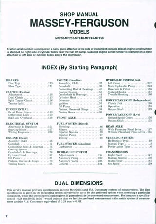
  • 1. SHOP MANUAL MASSEY-FERGUSON MODELS MF230-MF235-MF240-MF245-MF250 Tractor serial number is stamped on a name plate attached to the side of instrument console. Diesei engine serial number is stamped on right side of cyiinder block near the fuel lift pump. Gasoline engine serial number is stamped on a piate attached to ieft side of cyiinder biock above the distributor. INDEX (By Starting Paragraph) BRAKES Disc Type 173 Shoe Type 171 CLUTCH (Engine) Adjustment 110 Dual Clutch 113 Split Torque Clutch 116 Tractor Split 112 DIFFERENTIAL Bevel Drive Gears 163 Differential Lock 160 R&R and Overhaul 158 ELECTRICAL SYSTEM Alternator & Regulator 101 Starting Motor 107 Wiring Diagrams 239 ENGINE (Diesel) Assembly, R&R 56 Camshaft 71 Connecting Rods & Bearings . . . . 75 Cooling System 82 Crankshaft & Bearings. 76 Cylinder Head 57 Oil Pump 81 Pistons, Sleeves & Rings . 73 Timing Gears 65 ENGINE (Gasoline) Assembly, R&R 25 Camshaft 36 Connecting Rods & Bearings . . . . 40 Cooling System 50 Crankshaft & Bearings 41 Cylinder Head .26 (jiovernor .48 Ignition 53 Oil Pump 44 Pistons, Sleeves & Rings 38 Timing Gears 35 FRONT AXLE 1 FUEL SYSTEM (Diesel) Bleeding 86 Filters 85 Injector Nozzles 89 Injector Pump 97 Timing 98 FUEL SYSTEM (Gasoline) Carburetor 46 HYDRAULIC SYSTEM Adjustments 194 Auxiliary Pump 232 Auxiliary Valve .235 General 184 HYDRAUUC SYSTEM Cont. Lift Cover 207 Main Hydraulic Pump 223 Reservoir & Filter 185 System Checks 187 Trouble-Shooting 186 POWER TAKE-OFF (Independent) Clutch Unit 180 Operation 178 Output Shaft 179 POWER TAKE-OFF (Live) Ground Speed Gears 176 Output Shaft 175 REAR AXLE With Planetary Final Drive 167 Without Planetary Final Drive . 165 STEERING SYSTEM Hydrostatic Type 18 Manual Type . 3 Power Assist Type 6 TRANSMISSION Eight Speed 127 Manual Shuttle 136 Multi-Power 145 Six Speed 119 DUAL DiMENSiONS This service manual provides specifications in both Metric (SI) and U.S. Customary systems of measurement. The first specification is given in the measuring system perceived by us to be the preferred system when servicing a particular component, while the second specification (given in parenthesis) is the converted measurement. Fbr instance, a specifica- tion of *'0.28 mm (0.011 inch)'* would indicate that we feel the preferred measurement is the metric system of measure- ment and the U.S. Customary equivalent of 0.28 mm is O.OIL
  • 2. CONDENSED SERVICE DATA MF230 MF235 GENERAL Engine Make Engine Model Number of Cylinders Bore Stroke Displacement Cylinder Sleeves Electrical System TUNE-UP Firing Order Valve Clearance, Cold— Intake Exhaust Valve Clearance, Hot- Intake Exhaust Valve Face Angle- Intake Exhaust Valve Seat Angle- Intake Exhaust Injection Timing, Static Injector Opening Pressure.... New Used Ignition Timing Ignition Point Gap Spark Plug Gap Groverned Speeds, Engine Rpm- Low Idle High Idle Full Load Rated Power At Pto Shaft Diesel Perkins AD3.152 3 91.44 mm (3.6 in.) 127.0 mm (5.0 in.) 2.5 L (152 cu. in.) Dry Gasoline Continental Z-145 4 85.72 mm (3.375 in.) 103.2 mm (4.063 in.) 2.4 L (145 cu. in.) Wet Diesel Perkins AD3.152 3 91.44 mm (3.6 in.) 127.0 mm (5.0 in.) 2.5 L (152 cu. in.) Dry 12 Volt, Negative Ground Gasoline Continental Z-145 4 85.72 mm (3.375 in.) 103.2 mm (4.063 in.) 2.4 L (145 cu. in.) Wet 1-2-3 1-3-4-2 1-2-3 1-3-4-2 0.30 mm (0.012 in.) 0.30 mm (0.012 in.) 0.25 mm (0.010 in.) 0.25 mm (0.010 in.) 35° 35° 35° 35° 24° BTDC 19235 kPa (2790 psi) 17720 kPa (2570 psi) * • * > 725-775 2135-2185 2000 25.75 kW (34.5 hp) 0.33 mm (0.013 in.) 0.38 mm (0.015 in.) 0.28 mm (0.011 in.) 0.33 mm (0.013 in.) 30° 44° 30° 45° . . . . 8° BTDC 0.45-0.55 mm (0.017-0.022 in.) 0.63 mm (0.025 in.) 725-775 2200-2250 2000 25.6 kW (34.3 hp) 0.30 mm (0.012 in.) 0.30 mm (0.012 in.) 0.25 mm (0.010 in.) 0.25 mm (0.010 in.) 45° 45° 45° 45° 24° BTDC 18755 kPa (2720 psi) 17240 kPa (2500 psi) . •. • 725-775 2400-2450 2250 31.6 kW (42.4 hp) 0.33 mm (0.013 in.) 0.38 mm (0.015 in.) 0.28 mm (0.011 in.) 0.33 mm (0.013 in.) 440 30** 45** . . . . 8° BTDC 0.45-0.55 mm (0.017-0.022 in.) 0.63 mm (0.025 in.) 725-775 2425-2500 2250 30.7 kW (41.1 hp) CAPACITIES Cooling System. . . Crankcase* Hydraulic System. Power Steering. . . Fuel Tank * Add 0.95 L ( 1 U.S. quart) if filter is changed. • (5 U.S. qts.) — 30.3 L — • (8 U.S. gals.) — 0.95 L — • (1 U.S. qt.) 53 L (14 U.S. gals.) 9.9 L 9.5 L 9.9 L 9.5 L (10.5 U.S. qts.) (10 U.S. qts.) (10.5 U.S. qts.) (10 U.S. qts.) 4.7 L
  • 3. MF230 MF236 Diesel Gasoline Diesel SIZES-CLEARANCES Crankshaft Main Journal- Diameter 69.81-69.82 mm (2.7485-2.7490 in.) Bearing Clearance 0.08-0.13 mm (0.003-0.005 in.) Crankshaft Crankpin— Diameter 57.11-57.12 mm (2.2485-2.2490 in.) Bearing Clearance 0.06-0.10 mm (0.0025-0.0040 in.) Crankshaft End Play 0.05-0.38 mm (0.002-0.015 in.) Camshaft Journal Diameter- Front 47.4747.50 mm (1.869-1.870 in.) Center 47.22-47.24 mm (1.859-1.860 in.) Rear 46,71-46.74 mm (1.839-1.840 in.) Camshaft Bearing Clearance 0.10-0.20 mm (0.004-0.008 in.) Piston Pins- Diameter 31.744-31,750 mm (1.2498-1.2500 in.) Clearance in Bushing 0.01-0.04 mm (0.0004-0.0017 in.) TIGHTENING TORQUES** Cylinder Head Connecting Rods Refer to Text Main Bearings 149-156 N m (110-115 ft.-lbs.) Flywheel 101-108 N-m (75-80 ft.-lbs.) Oil Pan 26-28 N m (19-21 ft.-lbs.) Intake Manifold 8-12 N m (6-9 ft.-lbs.) Exhaust Manifold 16-20 N m (12-15 ft.-lbs.) ** Torque figures apply with threads clean and lightly oiled, 57.13-57.15 mm (2.249-2.250 in.) 0.013-0.081 mm (0.0005-0.0032 in.) 49.49-49.21 mm (1.9365-1.9375 in.) 0.015-0.078 mm (0.0006-0.0031 in.) 0.10-0.20 mm (0.004-0.008 in.) 45.92 45.95 mm (1.808-1.809 in.) 44.34-44.36 mm (1.745-1.746 in.) 42.75-42.77 mm (1.683-1.684 in.) 0,065-0.115 mm (0.0025-0.0045 in.) 21.821-21.826 mm (0.8591-0.8593 in.) 0.005-0.015 mm (0.0002-0,0006 in.) 69.81-69.82 mm (2.7485-2.7490 in.) 0.08-0.13 mm (0.003-0.005 in.) 57.11-57.12 mm (2.2485-2.2490 in,) 0.06-0,10 mm (0.0025-0.0040 in.) 0.05-0.38 mm (0.002-0,015 in.) 47.47-47,50 mm (1.869-1.870 in.) 47,22-47.24 mm (1.859-1.860 in.) 46.71-46.74 mm (1.839-1,840 in,) 0,10-0.20 mm (0.004-0,008 in.) 31.744-31.750 mm (1.2498-1.2500 in.) 0.01-0.04 mm (0.0004-0.0017 in.) Gasoline 57.13-57.15 mm (2.249-2.250 in.) 0,013-0,081 mm (0.0005-0.0032 in.) 49.19-49.21 mm (1,9365-1.9375 in.) 0.015-0.078 mm (0,0006-0.0031 in.) 0,10-0.20 mm (0,004-0.008 in.) 45.92-45.95 mm (1.808-1.809 in.) 44.34-44.36 mm (1.745-1.746 in.) 42.75-42.77 mm (1,683-1.684 in.) 0,065-0,115 mm (0.0025-0.0045 in.) 21.821-21.826 mm (0,8591-0.8593 in.) 0.005-0.015 mm (0.0002-0.0006 in.) 95-101 (70-75 ft 54-61 N m (40-45 ft.-lbs.) 115-129 N-m (85-95 ft.-lbs.) 95-101 N-m (70-75 ft.-lbs.) 16-22 N-m (12-16 ft.-lbs.) 27-41 N-m (20-30 ft.-lbs.) 27-41 N-m (20-30 ft.-lbs.) N-m .-lbs.) Refer to Text 149-156 N-m (110-115 ft.-lbs.) 101-108 N-m (75-80 ft.-lbs.) 26-28 N-m (19-21 ft.-lbs.) 8-12 N*m (6-9 ft.-lbs.) 16-20 N-m (12-15 ft.-lbs,) 54-61 N-m (40-45 ft.-lbs.) 115-129 N-m (85-95 ft.-lbs.) 95-101 N-m (70-75 ft.-lbs.) 16-22 N-m (12-16 ft.-lbs.) 27-41 N-m (20-30 ft.-lbs.) 2741 N-m (20-30 ft.-lbs.) CONDENSED SERVICE DATA GENERAL Engine Make Engine Model Number of Cylinders Bore Stroke Displacement Cylinder Sleeves.... Electrical System ... MF240 Diesel Perkins AD3.152 3 91.44 mm (3.6 in.) 127.0 mm (5.0 in.) 2,5 L (152 cu. in,) Dry MF245 Diesel Perkins AD3.152 3 91.44 mm (3.6 in.) 127.0 mm (5.0 in.) 2.5 L (152 cu. in.) Dry 19 Vnlt Nporfltiv Gasoline Continental Z-145 4 85.72 mm (3.375 in.) 103.2 mm (4.063 in.) 2.4 L (145 cu. in.) Wet # * firnund MF250 Diesel Perkins AD3.152 3 91,44 mm (3.6 in,) 127.0 mm (5.0 in.) 2.5 L (152 cu. in.) Dry
  • 4. MF240 Diesel TUNE-UP Firing Order 1-2-3 Valve Clearance, Cold- Intake 0.30 mm (0,012 in.) Exhaust 0.30 mm (0.012 in.) Valve Clearance, Hot- Intake 0.25 mm (0.010 in.) Exhaust 0.25 mm (0.010 in,) Valve Face Angle- Intake 35*" Exhaust 35° Valve Seat Angle- Intake 35° Exhaust 35° Injection Timing, Static 24° BTDC Injector Opening Pressure- New 18755 kPa (2720 psi) Used 17720 kPa (2570 psi) Ignition Timing . . . . Ignition Point Gap . . . . Spark Plug Gap Groverned Speeds, Engine Rpm— Low Idle 725-775 High Idle 2135-2185 Full Load 2000 Rated Power at Pto Shaft 25.9 kW (34.8 hp) CAPACITIES Cooling System 9.9 L (10.5 U.S, qts.) Crankcase* 5,9 L (6.2 U,S, qts.) Hydraulic System 32,5 L (8.6 U.S. gals.) Power Steering Fuel Tank 47.9 L (12,6 U.S. gals.) * Add 0.95 L (1 U.S. quart) if filter is changed. SIZES-CLEARANCES Crankshaft Main Journal- Diameter 69.81 69.83 mm (2.7485-2.7493 in.) Bearing Clearance 0.05-0.11 mm (0.002-0.004 in.) Crankshaft Crankpin— Diameter 57.11-57.12 mm (2.2485-2.2490 in.) Bearing Clearance 0,06-0.10 mm (0.0025-0.0040 in.) Crankshaft End Play 0.05-0.38 mm (0.002-0.015 in.) Camshaft Journal Diameter- Front 47.47-47.50 mm (1.869-1.870 in.) Center 47,22-47.24 mm (1.859-1.860 in.) Diesel 1-2-3 0.30 mm (0.012 in.) 0.30 mm (0.012 in.) 0,25 mm (0.010 in.) 0.25 mm (0.010 in,) 45° 45" 45** 45° 16° BTDC 18755 kPa (2720 psi) 17240 kPa (2500 psi) MF245 Gasoline 1-3-4-2 0.33 mm (0.013 in.) 0.38 mm (0.015 in.) 0.28 mm (0.011 in.) 0.33 mm (0.013 in.) 30° 440 30° 45° 725775 2400-2450 2250 32.0 kW (42,9 hp) 9.9 L (10.5 U.S, qts.) 4.7 L (5 U.S. qts,) 30.3 L (8 U.S. gals.) 0.95 8° BTDC 0.45-0.55 mm (0.017-0,022 in.) 0,63 mm (0.025 in.) 725-775 2425-2500 2250 30.5 kW (41 hp) 9.5 L (10 U.S. qts.) 4.7 L (5 U.S. qts,) 30.3 L (8 U.S. gals.) MF250 Diesel 1-2-3 0,30 mm (0.012 in.) 0.30 mm (0.012 in.) 0.25 mm (0,010 in.) 0,25 mm (0.010 in,) 35' 35° 35° 35 = 16° BTDC 18755 kPa (2720 psi) 17720 kPa (2570 psi) 725-775 2400-2450 2250 30.4 kW (40.8 hp) 9.9 L (10.5 U.S. qts.) 5.9 L (6.2 U.S. qts.) 41.8 L (11 U.S. gals.) 53 L (14 U.S. gals.) 69.81-69,83 mm (2.7485-2.7492 in.) 0.08-0.13 mm (0.003-0.005 in.) 57.11-57.12 mm (2.2485 2.2490 in.) 0.06-0.10 mm (0.0025-0.0040 in.) 0.05-0,38 mm (0.002-0.015 in.) 47,47-47,50 mm (1.869-1.870 in.) 47.22-47.24 mm (1.859-1.860 in.) (1 U.S. qt) 53 L (14 U.S. gals.) 57.13-57.15 mm (2.249-2.250 in.) 0.013-0,081 mm (0,0005-0.0032 in.) 49.19-49.21 mm (1.9365-1.9375 in.) 0.015-0.078 mm (0.0006-0.0031 in.) 0.10-0.20 mm (0.004-0.008 in.) 45.92-45,95 mm (1.808-1.809 in.) 44.34-44.36 mm (1.745-1.746 in.) 47.9 L (12.6 U.S. gals.) 69.81-69.83 mm (2.7485-2.7493 in.) 0.05-0.11 mm (0.002-0.004 in.) 57.11-57.12. mm (2,2485-2.2490 in.) 0.06-0.10 mm (0.0025-0.0040 in.) 0.05-0.38 mm (0,002-0.015 in,) 47.47-47.50 mm (1.869-1.870 in.) 47.22-47,24 mm (1.859-1.860 in.)
  • 5. Paragraph 1 MASSEY-FERGUSON MF240 Diesel SIZES-CLEARANCES (Cont.) Rear 46.71-46.74 mm (1.839-1.840 in.) Camshaft Bearing Clearance 0.10-0.20 mm (0.004-0.008 in.) Piston Pins- Diameter 31.744-31.750 mm (1.2498-1.2500 in.) Clearance in Rod Bushing 0.01-0.04 mm (0.0004-0.0017 in.) TIGHTENING TORQUES** Cylinder Head 95 N-m (70 ft.-lbs.) Connecting Rods Refer Main Bearings 150 N-m (110 ft.-lbs,) Flywheel 105 N-m (78 fl.-lbs.) Oil Pan 18 N-m (14 ft.-lbs.) Intake Manifold 18 N-m (14 ft.-lbs.) Exhaust Manifold 18 N-m (14 ft.-lbs.) ** Torque figures apply with threads clean and lightly oiled. MF245 Diesel Gasoline 46.71-46.74 mm (1.839-1.840 in.) 0.10-0.20 mm (0.004-0.008 in.) 31.744-31.750 mm (1.24984.2500 in.) 0.01-0.04 mm (0.0004-0.0017 in.) to 95 N-m (70 ft.-lbs.) Text 150 N-m (110 ft.-lbs.) 105 N-m (78 ft.-lbs.) 18 N-m (14 ft.-lbs.) 18 N-m (14 ft.-lbs.) 18 N-m (14 ft.-lbs.) 42.75-42.77 mm (1.6834.684 in.) 0.065-0.115 mm (0.0025-0.0045 in.) 21.821-21.826 mm (0.8591-0.8593 in.) 0.005-0.015 mm (0.0002-0.0006 in.) 95-101 N-m (70-75 ft.-lbs.) 54-61 N-m (40-45 ft.-lbs.) 115-129 N-m (85-95 ft.-lbs.) 95-101 N-m (70-75 ft.-lbs.) 16-22 N-m (12-16 ft.-lbs.) 27-41 N-m (20-30 ft.-lbs.) 27-41 N-m (20-30 ft.-lbs.) MF250 Diesel 46.71-46.74 mm (1.839-1.840 in.) 0.10-0.20 mm (0.004-0.008 in.) 31.744-31.750 mm (1.24984.2500 in.) 0.01-0.04 mm (0.0004-0.0017 in.) 95 N-m (70 ft.-lbs.) Refer to Text 150 N-m (110 ft.-lbs.) 105 N-m (78 ft.-lbs.) 18 N-m (14 ft.-lbs.) 18 N-m (14 ft.-lbs.) 18 N-m (14 ft.-lbs.) FRONT SYSTEM AXLE ASSEMBLY All Models 1. Several different front axles are used as shown in Figa 1,2,3,4 and 5. Axle extension (7—Fig. 1,2,3 and 5) can be removed from adjustable axle models by first disconnecting drag link and/or tie rod and power steering cylinder (if so equipped) from steering arm. Remove bolts attaching axle extension to center member (5), then withdraw axle exten- sion. TD remove center member (5), first 1 2 1 0 support front oftractor and remove hood, side panels, grille support frame, radiator and axle extensions (if so equip- ped). Disconnect hydraulic lines from power steering cylinders (if so equipped). Remove axle pivot pin retaining screw (4) and inner snap ring (3). Withdraw pivot pin and remove axle center Fig. 1—explod0d vi^w of $wopt back axfe used on some MF230 and mF235 mode/s. Refar to Fig. 2 for lagand excepf radfus rods (11). Fig. 2—Exploded view of typical straight axle standard on MF235 models and all Vineyard models. 1. Pivot pin 6. Bushing 2. Front support 7. Axle extension 12. Dust seal 3. Snap ring 8. Spindle 13. Steering arm 4. Pivot pin retaining screw 9. Bearing 14. Drag link 5. Axle center member 10. Bushing 16. Shim
  • 6. SERVICE MANUAL Paragraphs 2-3 13 1 4 Fig. 3—Exploded view of semi-swept back axle stand- ard on MF245 models. Refer to Fig. 2 for iegend except tie rod (16). 13 Fig. 5—Exploded view of adfustabie front axie assembiy used on Modeis MF240 and MF250. Refer to Fig. 2 for legend except for the following: 20. Steering cylinder 21. Cylinder bracket 22. Seal 23. Inner bearing 24. Wheel hub 25. Outer bearing 26. Hub cap Fig. 4-^Expioded view of nonadjustable front axie used on MF235 and h/iF245 Orctiard modeis. Refer to Fig. 2 for iegend except for wasiters (i7) and tie rod (16). member. Unbolt and remove front sup- port (2) if necessary. Axle pivot bushings (6) and spindle bushings (10) should be renewed if ex- cessively worn. Pivot bushings (6) should be installed 0.5 mm (0.020 inch) below flush with inner faces of support hous- ing. Be sure bushings are installed with hole aligned with grease passage. Make certain pivot pin slides freely through bushings after installation. Spindle bushings (10) must be reamed to provide desired fit to spindle. 1b reinstall, reverse the removal procedure. Measure axie center member end play in support housing using a feeler gage. Select shims (15) to provide 0.05-0.25 mm (0.002-0.010 inch) end play. Lubricate with multipurpose lithium base grease. TOE-IN, TIE RODS AND/OR DRAG LINKS All Models 2. Automotive type tie rod and drag link ends are used. Units are nonad- justable and should be renewed if ex- cessively worn. Recommended toe-in is 3 mm (1/8 inch). On models with two drag links, adjust each an equal amount to obtain correct toe-in. On models with tie rod (16—Fig. 3 or 4), loosen locknuts and clamps, then turn adjusting sleeve to provide correct toe in. MANUAL STEERING GEAR This section covers the manual steer- ing gear used on MF230 and MF235 tractors without power assist steering or hydrostatic power steering. All Models So Equipped 3. LUBRICATION AND ADJUST- MENT. The steering gear should be filled to the level ofthe opening for plug (25—Fig. 6) with SAE 90 gear lubricant. Backlash between the ball nut (20) and left sector gear (10) and between the right and left sector gears (10 and 15) can be adjusted while unit is installed. Ib adjust, loosen four screws that attach the left and right pinion housings (4L and 4R) to the steering gear housing, then rotate the right pinion housing (4R) clockwise to the end of the bolt slota Rotate the left pinion housing (4L) counterclockwise until all backlash is eliminated between left pinion and ball nut, then tighten the four screws retain- ing left pinion housing. Rotate the right pinion housing counterclockwise until all backlash is eliminated between the
  • 7. Paragraphs 4-5 MASSEY-FERGUSON two pinions, then tighten the four screws retaining the right pinion housing. If ad- ditional adjustment is required, refer to paragraph 5. 4. REMOVE AND REINSTALL. To remove the manual steering gear assembly, first remove the battery and the steering wheel. Disconnect the oil pressure line at the gage and tachometer cable at both ends, then remove the tachometer cable and cable housing. Mark all wires to facilitate assembly, then disconnect all wires from instru- ment panel gages. Remove lights from panel gages and disconnect fuel shut-off from injection pump (diesel models). Remove the complete instrument panel with gages. Disconnect wires from starter switch and light switch, then un- bolt and remove the rear hood assembly with light switch and starter switch in- stalled. Disconnect linkage from both ends ofthe throttle cross shaft, then slide shaft from left side oftractor. Remove the complete air cleaner assembly and the battery platform. Disconnect drag links from both pitman arms, remove the six retaining screws, then lift the steering gear from the tractor. Reinstall by reversing the removal pro- cedure. Be careful to connect wires to in- struments correctly. 5. OVERHAUL. To overhaul the removed unit, first remove the right pin- ion housing (4R—Fig. 6) and shaft (15), then remove the left pinion housing (4L) and shaft (10). Unbolt shaft housing (24) and withdraw housing and shaft (20). Eleven loose balls should fall from up- per bearing (21) and eleven from lower bearing (19). Pitman shafts (10 and 15) and related parts can be withdrawn from housing (4L or 4R) after snap ring (8) is removed as shown in Fig. 7. Parts of the ball nut and shaft (20-Fig. 6) are not available separately and should not be disassembled. Press new bushings (3,11 and 17) into bores of respective housings until flush to 0.8 mm (1/32 inch) below flush with outer edge of bore. Assemble parts (6,7,8,9,12 and 13) onto pitman shaft (10) and parts (6,8,9,12,13 and 16) onto pit- man shaft (15) before inserting into housings (4L and 4R). Add more shims (12), if necessary, to remove all end play from bearing. Use grease to hold the eleven balls (19 and 21) into each race, then insert shaft fig. 6~-Exptoded view of typical manuai steering gear used on MF230 and some MF235 models. 1. Left pitman arm 2. Oil seal 3. Bushing 4L. Left pinion housing 4R. Right pinion housing 5. "0" ring 6. Bearing 7. Left sleeve 8. Snap ring 9. Clip 10. Left pitman shaft 11. Bushing 12. Shim 13. Retainer 14. Steering gear housing 15. Right pitman shaft 16. Right sleeve 17. Bushing 18. Right pitman arm 19. Lower hearing 20. Shaft & ball nut 21. Upper bearing 22. Shims ; ' 23. "O" ring 24. Shaft housing 25. Fill plug 26. Top bushing and ball nut (20) into shaft housing (24). Place shims (22) and " C ring (23) onto housing (24), then install into steering gear housing (14). Shims (22) are available in 0.13-0.25 mm (0.005-0.010 inch). Install only enough shims to pro- vide 0.03-0.13 mm (0.001-0.005 inch) preload for bearings (19 and 21). After steering shaft ball nut is in- stalled, turn the steering shaft until the ball nut is at bottom. Position the steer- ing gear as normally installed on the tractor, and install the left pitman shaft (10) and housing (4L) assembly. The flat identification boss on left housing (4L) should be down when installed. The marked (3rd) tooth on left pinion (10) should be aligned with center valley of ball nut rack (20) as shown in Fig. 8. Turn the steering shaft until ball nut is moved to top and install the right pit- man shaft (15—Fig. 6) and housing (4R) assembly. The first tooth on right pinion (15) should be aligned with the first valley on left pinion (10) as shown in Fig. 9. The flat identification boss on right housing (4R—Fig. 6) should be toward front when installed correctly. Ib adjust the backlash, rotate the right pinion housing (4R) clockwise to end of bolt slots and temporarily tighten re- taining screw. Rotate the left pinion housing (4L) counterclockwise until all Fig. 7—The snap ring must be removed as shown before pitman shaft can be removed from housing. Fig. 8—r/ie mariced (3rd) tooth of the left pinion gear (70) shouid be aiigned with the center vaiiey of racic (20).
  • 8. Thank you very much for your reading. Please Click Here. Then Get COMPLETE MANUAL. NO WAITING NOTE: If there is no response to click on the link above, please download the PDF document first and then click on it.
  • 9. SERVICE MANUAL Paragraphs 6-9 Fig. 9—Install the right pinion with first tooth (15) aligned with first vaiiey (10) on the other pinion. backlash is eliminated, then tighten the four housing retaining screws. Rotate the right pinion housing (4R) counter- clockwise until all backlash is removed from the right pitman shaft, then tighten the four retaining screwa Check for correct assembly by locating the center (straight ahead) position of the steering shaft (20). With steering shaft straight ahead, the blank splines on both pitman shafts (10 and 15) should be vertical. The small flat mounting boss at rear of steering gear housing will also be vertical when installed on tractor. Fill steering gear housing to level ofplug (25) with SAE 90 gear oil. POWER ASSIST STEERING SYSTEM This section covers the power steering system available on Models MF230, MF235 (except Orchard), MF240, MF245 Vineyard and MF250. LUBRICATION AND BLEEDING All Models So Equipped 6. Recommended oil for power steering system is Massey-Ferguson Permatran III Oil. Check power steering reservoir oil level with engine running after all air is bled from system. Power steering system capacity is approximately 0.95 L (1 U.S. quart). Air can be bled from power steering system by running engine and cycling steering from full left to full right, then oack to full left several timea Repeat un- til there are no air bubbles present in oil reservoir. Make certain oil level is main- tained during bleeding process to avoid starving the pump of oil. SYSTEM OPERATING PRESSURE AND RELIEF VALVE All Models So Equipped 7. A pressure test of steering hydraulic system will disclose whether the pump relief valve or some other unit in the system is malfunctioning. Ib check relief pressure, install a "T" fitting at pump pressure port, reattach pressure hose to one port of "T" and a 20000 kPa (3000 psi) pressure gage to the other port. Start engine and operate at 2000 rpm. Turn steering wheel to full turn in either direction and observe gage pressure reading. Normal relief pressure is ap- proximately 8300 kPa (1200 psi). The relief valve on models equipped with gasoline engine is adjusted after removing reservoir (27—Fig. 11) and turning screw (24). The relief valve on models equipped with diesel engine is also adjusted after removing reservoir (27—Fig. 10) and turning adjusting screw (24). One full turn of relief valve screw should change pressure approximately 2100 kPa (300 psi) on Models MF230, MF235 and MF245. On Models MF240 and MF250, a pressure change ofapprox- imately 3100 kPa (450 psi) should result from one turn of adjusting screw. 20 Reinstall reservoir, refill with oil and recheck pressure after changing relief valve setting. POWER STEERING PUMP The pump shown in exploded view Fig. 10 is used on diesel models; the pump in Fig. 11 on gasoline models. Refer to the appropriate following paragraphs for service. All Models 8. REMOVE AND REINSTALL. Clean the area thoroughly before discon- necting any lines. Disconnect lines, remove mounting screws and withdraw pump. When reinstalling, tighten retaining bolts to 27 N ' m (20 fl.-lba) torque. Refill reservoir with fluid and bleed air from system as outlined in paragraph 6. Diesel Models 9. OVERHAUL. Mark the pump housing (8—Fig. 10) and reservoir (27) before removing reservoir. Filter (16) can be removed after reservoir. Remove nut, gear (1), key and spacer (2). Establish the setting ofthe relief valve plug (24) before removing the plug. Remove the screws attaching body (17) and shield (20) to the housing (8). Remove gears (10 and 11), Woodruff key (6), idler shaft (13) and pin 25 Fig, 10—Exploded view of power eieeHng pump u—d on Hiodela MF230, H/IFZSS and lliF24S equipped wim dieeel engine. Pump ueed on Modeie II0F24O end mF2S0 te elmller except duel eprtnge em ueed on relief yelve end eprtng guide pin (23} le not ueed^lneeteiHmelocetkHi of preeeun line {P) end ntum line (R), 1. Gear 8. Housing 15. Gasket 22. Spring 2. Spacer 9. Needle bearings 16. Filter 23. Pin 3. Snap ring 10. Drive gear 17. Body 24. Relief adjusting plug 4. Bearing 11. Driven gear 18. Dowel pins 25. Nut 5. Shaft 12. Rings 19. Gasket 26. "O" ring 6. Woodruff keys 13. Idler shaft 20. Shield 27. Reservoir 7. Seal 14. Pin 21. Relief plunger 28. Fill plug
  • 10. Paragraphs 10-11 (14). Remove snap ring (3), then bump shaft (5) and bearing (4) out front ofhous- ing bore. Inspect all parts for scoring, wear or other damage and renew if necessary. Always renew all "O" rings, gaskets and oil seal. Install new oil seal (7) with lip facing inward and front of seal flush with outer surface of housing. When renewing nee- dle bearings (9), press against niimbered side of bearing. Bearings should be slightly below flush with machined sur- face of housing. Press bearing (4) onto shaft (5), then install the shaft and bear- ing in bore of housing (8). Install snap ring (3), spacer (2), key (6) and gear (1), then install retaining nut. Install the other key (6) in shaft and slide gear (10) onto key (6) in shaft and slide gear (10) onto shaft over the key. Install the idler shaft and gear assembly (11,12,13 and 14). Position thin gasket (15) around gears and locate body (17) over gears be- ing careful not to damage the gasket. In- stall the thicker gasket (19) and plate (20) and tighten the assembly screws to 11-14 N • m (8-10 ft.-lba) torque. Use care when assembling relief valve (21, 22,23, 24 and 25). Install the adjusting plug (24) as near as possible to position from which it was removed. Reinstall pump and check relief pressure as outlined in paragraph 7. Gasoline Models 10. OVERHAUL. Remove reservoir cover (29-Fig. 11), filter (16), stud (30) and screw (31), then lift off reservoir (27). Establish the setting of the relief valve plug (24) before removing plug. Remove 1 7 1 0 1 3 f/g. 11—Exploded view of power steering pump used on Modeis MF230, MF235 and MF245 equipped with gasoiine engine, inset shows iocation of pressure iine (P) and return iine (R). 1. Gear 9. Needle bearings 2. Spacer 10. Drive gear 17. Body . 3. Snap ring 11. Driven gear 18. Dowel pin 25. O rings 4. Bearing 12. Rings 19. Gasket 26. O ring 5. Shaft 13. Idler shaft 21. Relief plunger 27. Reservoir 6. Woodruff keys 14. Pin 22. Springs 29. Cover 7. Seal 15. Gasket 23. "O" ring 8. Housing 16. Filter 24. Relief adjusting plug 30. Stud 31. Screw MASSEY-FERGUSON screws attaching body (17) to the hous- ing (8) and remove body. Remove gears (10 and 11), Woodruff key (6), idler shaft (13) and pin (14). Remove nut, gear (1), sleeve (2) and snap ring (3), then bump shaft (5) and bearing (4) out front of housing. Install new seal (7) with lip toward rear of pump and front of seal flush with the step in front of housing bore. Press new bearings (9) into bores in body (17) and housing (8) until bearing is just below flush. Press only on numbered side of bearing which should be toward gears (10 and 11). Press bearing (4) onto shaft (5), then install the shaft and bearing in bore of housing (8). Install snap ring (3), spacer (2), key (6) and gear (1), then in- stall retaining nut. Install other key (6) in shaft and slide gear (10) onto shaft over key. Install the idler shaft and gear assembly (11, 12, 13 and 14), Position gasket (15) around gears and locate body (17) over gears being careful not to damage gasket. Install and tighten assembly screws to 11-14 N • m (8-10 ft.- lbs.) torque. Install relief valve (21, 22, 23 and 24). Install plug (24) as near as possible to original location to facilitate relief setting. Reinstall pump and check relief valve pressure setting as outlined in paragraph 7. STEERING GEAR AND CONTROL VALVE Models MF230-MF235-MF245 The steering gear assembly includes the power steering control valve, power assist piston and cylinder as well as steering shaft, rack, and pitman shafts necessary for manual steering. 11. REMOVE AND REINSTALL. To remove the power steering gear, first remove the battery and the steering wheel. Disconnect the oil pressure line at gage and tachometer cable at both ends, then remove the tachometer cable and cable housing. Mark all wires to facilitate reassembly, then disconnect all wires from instrument panel gages. Remove lights from panel gages and disconnect fuel shut-off from injection pump (diesel models). Remove the com- plete instrument panel with gages. Disconnect wires from starter switch and light switch, then unbolt and remove the rear hood assembly with starter and light switches installed. Disconnect linkage from both ends of the throttle cross shaft, then slide shaft from left side of tractor. Remove the complete air cleaner assembly and the battery platform. Clean the area thoroughly before disconnecting any power steering lines. Disconnect hydraulic lines and plug all openings to prevent entrance of 10