BEST ✨ Call Girls In Indirapuram Ghaziabad ✔️ 9871031762 ✔️ Escorts Service...
Planning a microwavelink
1. 8000 Lee Highway
Falls Church, VA 22042
703-205-0600
www.ydi.com
Planning a Microwave Radio Link
By Michael F. Young
President and CTO
YDI Wireless
Background
Most installers know that clear line of sight is required between two antennas, but there is a lot more to it than
that. In this article, the basics of designing and planning a microwave radio link will be discussed.
Some manufacturers of OFDM (Orthogonal Frequency Division Multiplexing)-based equipment claim to offer
fixed wireless systems with non-line-of-sight functionality. However, this article does not discuss the RF
propagation issues associated with non-line-of-sight gear.
Explanation of Terms
Before getting to the nuts and bolts of designing a link, some fundamental terms and concepts need to be
reviewed.
Free Space Loss
As signals spread out from a radiating source, the energy is spread out over a larger surface area. As this
occurs, the strength of that signal gets weaker. Free space loss (FSL), measured in dB, specifies how much the
signal has weakened over a given distance.
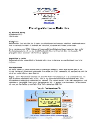
Figure 1 shows the formula to calculate FSL and what the theoretical loss would be at sample distances. The
type of antenna used has no effect on FSL, since at any appreciable distance all antennas look like a point-
source radiator. Note that the difference in FSL between a 2.4 GHz link and a 5.8 GHz link is always about 8 dB,
regardless of the distance. This is one of the reasons why 802.11a wireless local area network (WLAN) devices
will have less than half the range of a 2.4 GHz WLAN device (e.g., 802.11b).
Figure 1 – Free Space Loss (FSL)
2. Fresnel Zone
Radio waves travel in a straight line, unless something refracts or reflects them. But the energy of radio waves is
not “pencil thin.” They spread out the farther they get from the radiating source — like ripples from a rock thrown
into a pond.
The area that the signal spreads out into is called the Fresnel zone (pronounced fra-nell). If there is an obstacle
in the Fresnel zone, part of the radio signal will be diffracted or bent away from the straight-line path. The
practical effect is that on a point-to-point radio link, this refraction will reduce the amount of RF energy reaching
the receive antenna.
The thickness or radius of the Fresnel zone depends on the frequency of the signal — the higher the frequency,
the smaller the Fresnel zone. Figure 2 illustrates how the Fresnel zone is fattest in the middle. As with FSL, the
antennas used have no effect on the Fresnel zone.
Figure 2 – Fresnel Zone
Receive Signal Level
Receive signal level is the actual received signal level (usually measured in negative dBm) presented to the
antenna port of a radio receiver from a remote transmitter.
Receiver Sensitivity
Receiver sensitivity is the weakest RF signal level (usually measured in negative dBm) that a radio needs
receive in order to demodulate and decode a packet of data without errors.
Antenna Gain
Antenna gain is the ratio of how much an antenna boosts the RF signal over a specified low-gain radiator.
Antennas achieve gain simply by focusing RF energy.
If this gain is compared with an isotropic (no gain) radiator, it is measured in dBi. If the gain is measured against
a standard dipole antenna, it is measured in dBd. Note that gain applies to both transmit and receive signals.
Transmit Power
The transmit power is the RF power coming out of the antenna port of a transmitter. It is measured in dBm,
Watts or milliWatts and does not include the signal loss of the coax cable or the gain of the antenna.
3. Effective Isotropic Radiated Power
Effective isotropic radiated power (EIRP) is the actual RF power as measured in the main lobe (or focal point) of
an antenna. It is equal to the sum of the transmit power into the antenna (in dBm) added to the dBi gain of the
antenna. Since it is a power level, the result is measured in dBm.
Figure 3 shows how +24 dBm of power (250 mW) can be “boosted” to +48 dBm or 64 Watts of radiated power.
Figure 3 – Effective Isotropic Radiated Power (EIRP)
System Operating Margin
System operating margin (SOM) is the difference (measured in dB) between the nominal signal level received at
one end of a radio link and the signal level required by that radio to assure that a packet of data is decoded
without error (see Figure 4).
In other words, SOM is the difference between the signal received and the radio’s specified receiver’s
sensitivity. SOM is also referred to as link margin or fade margin.
Figure 4 – System Operating Margin (SOM)
4. Multipath Interference
When signals arrive at a remote antenna after being reflected off the ground or refracted back to earth from the
sky (sometimes called ducting), they will subtract (or add) to the main signal and cause the received signal to be
weaker (or stronger) throughout the day.
Signal-to-Noise Ratio
Signal-to-noise ratio (SNR) is the ratio (usually measured in dB) between the signal level received and the noise
floor level for that particular signal. The SNR is really the only thing receiver demodulators really care about.
Unless the noise floor is extremely high, the absolute level of the signal or noise is not critical.
Figure 5 illustrates that weaker signals are larger negative numbers. It also graphically shows how the SNR is
computed.
Figure 5 – Signal-to-Noise Ratio (SNR)
First Step in Planning a Link
Whether your link is point-to-point or point-to-multipoint, the first thing to do is to verify that it will have not only
clear line of sight, but at least 60 percent of the first Fresnel zone clear of obstructions as well. The longer the
distance, the more important this is. If the Fresnel zone is blocked, then you will get a lower signal level on the
distant end than expected — even if you can literally “see” the other antenna in the distance.
But even if your Fresnel zone is partially blocked, it is still possible to get a link, provided that your system was
designed to have a strong signal at the other end of the link. In planning long-range microwave links where you
are not sure that you have unobstructed line-of-site and clear Fresnel zone, an RF path analysis should be
done. There are many software packages available that have terrain data and can create a path profile from a
set of latitude/longitude coordinates. But these programs can only indicate for certain if a link will not work due to
terrain obstruction. A clear path on paper is not a guarantee that your link will work, since it does not show trees
or buildings. So even a “clear” link might have 80-foot trees in the way that could block the signal.
You could be wasting your time and money if you ignore Fresnel zone issues — or worse yet, no line-of-site —
and attempt to set up a link anyway. You will likely not have a reliable link, if one at all.
But assuming that you do have clear line-of-site and 60 percent of the first Fresnel zone clear (or nearly clear),
how can you know if you will have a good link or not? How much gain do your antennas need to have? How
5. much coax cable loss is too much? If your link is at 2.4 GHz, should external amplifiers be used? Or given your
fixed base station antenna with a pre-set gain, how far can you reach with the different types of client antennas?
And which clients will need amplification?
Why Perform an SOM Calculation?
By doing an SOM calculation, you can test various system designs and scenarios to see how much fade margin
(or “safety cushion”) your link will theoretically have.
Figure 6 illustrates a sample SOM calculation on a point-to-point link. It presumes that the antennas are aimed
at each other properly (i.e., they are in each others’ main lobe). To calculate SOM in the example, start with the
transmit power (+24 dBm), subtract the coax cable loss (1 dB), and add the transmit antenna gain (24 dBi). This
gives you the effective isotropic radiated power:
EIRP = TX Power - Coax Cable Loss + TX Antenna Gain.
Then subtract the FSL (130 dB), add the receiver antenna gain (24 dBi), subtract the coax cable loss (1dB) and
you get the signal reaching the receiver:
RX Signal = EIRP - FSL + RX Antenna Gain – Coax Cable Loss
Compute the difference between the received signal and the radio’s receiver sensitivity to determine the SOM.
In this example, the received signal is –60 dBm and the receiver’s sensitivity is –83 dBm giving a theoretical
SOM of 23 dB.
Figure 6 – Sample System Operating Margin (SOM) Calculation
What Is the Minimum SOM Needed?
Regarding the minimum SOM needed, there is no absolute answer to this question, but the higher it is, the
better. Most engineers agree that 20 dB or more is quite adequate. Some think as low as 14 dB is still good.
Others operate systems down to 10 dB or less.
The problem with accepting a lower SOM is that you have a smaller safety margin. You run the risk of your link
going down for such things as interference, an antenna off its aim, atmospheric conditions, moisture in your
6. coax, ice on the radome, or a host of other gremlins. So while a 14 dB SOM would work, there is not much
margin.
Real World Issues
In practice, the SOM is not the only determining factor. It’s the actual SNR at the receiver that makes a link
reliable. If you are getting noise or interference on your channel, your SNR will deteriorate. This could be an
issue if you are co-locating at a site with other radios operating in the same band. You need to find out what
frequency spectrum these radios are occupying. If these transmitter have energy or sideband noise on your
receive channel and their antennas are close to yours, you will likely get interference from them, perhaps to the
point where your link will not work.
Another consideration is that the SOM calculation is for a vacuum. In fact, there is some atmospheric absorption
of the RF energy that scatters and attenuates the signal. For example, tests on a 23-mile 5.8 GHz link vary as
much as +/-6 dB over course of a day. This variation is mostly caused by multipath interference and other
atmospheric variations.
Notice that with coax cable at the receiver and no amplifier at the receiver antenna, the SNR at the antenna
does not survive when it actually reaches the radio itself. In this case, the noise generated in the RF front-end of
the radio is a factor.
Note that if you do use an amplifier on the receive end, as shown in Figure 6, the SNR as it appears at the
antenna is preserved all the way down the coax to the radio. This phenomenon largely occurs because the low-
noise amplifier mounted on the pole sets the noise floor for the system.
Conclusion
To have some certainty as to whether your wireless link will be reliable, an RF path analysis and SOM
calculations need to be performed.
To help you with the SOM calculations, an on-line SOM calculator can be found at:
www.ydi.com/calculation/som.php