1. 24516 Page 108 Friday, October 26, 2001 9:32 AM
Description, TeSys protection components
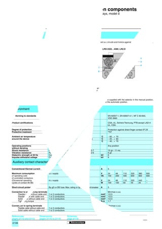
characteristics 3-pole thermal overload relays, model d
Description
Model d 3-pole thermal overload relays are designed to protect a.c. circuits and motors against overloads, phase failure,
long starting times and prolonged stalling of the motor.
LRD-01…35 LRD-3322…4369, LR2-D
1 1
6
2 RESET
2&5
4
37
5
A
3
41
3 50 R
3,5 0 1 46
M A E
S 4
5 STOP 3 2 TEST E
4 T
6
7
NO NC
98 97 95 96
1 Adjustment dial Ir
2 Test button
Operation of the Test button allows:
- checking of control circuit wiring,
- simulation of relay tripping (actuates both the N/O and N/C contacts).
3 Stop button. Actuates the N/C contact; does not affect the N/O contact.
2.3 4 Reset button
5 Trip indicator
6 Setting locked by sealing the cover.
7 Selector for manual or automatic reset. Relays LRD-01 to 35 are supplied with the selector in the manual position,
protected by a cover. Deliberate action is required to move it to the automatic position.
Environment
Conforming to standards EN 60947-1, EN 60947-4-1, NF C 63-650,
VDE 0660
Product certifications CSA, UL, Sichere Trennung, PTB except LAD-4:
UL, CSA.
Degree of protection Conforming to VDE 0106 Protection against direct finger contact IP 2X
Protective treatment Conforming to IEC 68 “TH”
Ambient air temperature Storage ˚C - 60…+ 70
around the device Normal operation, without derating (IEC 947-4-1) ˚C - 20…+ 60
Minimum and maximum operating temperatures ˚C - 40…+ 70
(with derating)
Operating positions In relation to normal, vertical mounting plane Any position
without derating
Shock resistance Permissible acceleration conforming to IEC 68-2-7 15 gn - 11 ms
Vibration resistance Permissible acceleration conforming to IEC 68-2-6 6 gn
Dielectric strength at 50 Hz Conforming to IEC 255-5 kV 6
Impulse withstand voltage Conforming to IEC 801-5 kV 6
Auxiliary contact characteristics
Conventional thermal current A 5
Maximum consumption a.c. supply V 24 48 110 220 380 600
of operating coils VA 100 200 400 600 600 600
of controlled contactors
(Occasional operating d.c. supply V 24 48 110 220 440 –
cycles of contact 95-96) W 100 100 50 45 25 –
Short-circuit protection By gG or BS fuse. Max. rating or by GB2 circuit-breaker A 5
Connection to screw clamp terminals Min/max c.s.a.
Flexible cable without cable end 1 or 2 conductors mm2 1/2.5
Flexible cable with cable end 1 or 2 conductors mm2 1/2.5
Solid cable without cable end 1 or 2 conductors mm2 1/2.5
Tightening torque N.m 1.7
Connection to spring terminals Min/max c.s.a.
Flexible cable without cable end 1 or 2 conductors mm2 1/2.5
Solid cable without cable end 1 or 2 conductors mm2 1/2.5
References: Dimensions: Schemes:
pages 2/112 and 2/113 pages 2/116 to 2/118 page 2/119
2/108 Schneider Electric
2. 24516 Page 109 Friday, October 26, 2001 12:37 PM
Characteristics TeSys protection components
3-pole thermal overload relays, model d
Electrical characteristics of power circuit
Relay type LRD- LR2- LRD- LR2- LRD- LR2- LRD-
01 to 16 D15pp 21 to 35 D25pp 3322 to D35pp 4365 to
33696 4369
LR3- LR3- LR3-
D01 to D16 D21 to D35 D3322 to
D33696
Tripping class To UL 508, EN 60947-4-1 10 A 20 10 A 20 10 A 20 10 A 2
Rated insulation voltage (Ui) Conforming to EN 60947-4-1 V 690 690 1000 1000
Conforming to UL, CSA V 600 600 600 600 except
LRD-4369
Rated impulse withstand
voltage (Uimp) kV 6 6 6 6
Frequency limits Of the operational current Hz 0…400 0…400 0…400 0…400
Setting range Depending on model A 0.1…13 12…38 17…10 80…140
4
Connection to screw clamp terminals Min/max c.s.a.
Flexible cable without cable end 1 conductor mm2 1.5/10 1.5/10 4/35 4/50 2.3
Flexible cable with cable end 1 conductor mm2 1/4 1/6 except 4/35 4/35
LRD-21: 1/4
Solid cable without cable end 1 conductor mm2 1/6 1.5/10 except 4/35 4/50
LRD-21: 1/6
Tightening torque N.m 1.7 1.85 2.5 9 9
Connection to spring terminals Min/max c.s.a.
Flexible cable without cable end 1 conductor mm2 1.5/4 – 1.5/4 – – – –
Solid cable without cable end 1 conductor mm2 1.5/4 – 1.5/4 – – – –
Operating characteristics
Temperature compensation ˚C - 20…+ 60 - 30…+ 60- - 30…+ 60 - 20…+ 60
Tripping threshold Conforming to EN 60947-4-1 A 1.14 ± 0.06 In
Sensitivity to phase failure Conforming to EN 60947-4-1 Tripping current 30 % of In on one phase, the others at In
Tripping curves
Time class 10 A Time class 20
Average operating time
Hours
Hours
related to multiples of the 2 2
current setting
1 1
40 40
20 20
Minutes
Minutes
10 10
4 4
2 2
1 1
40 40
20 20
Seconds
Seconds
10 10
1
4 4 2
1 3
2 2 2
1
3 1
0,8 0,8
0,8 1 2 4 6 10 17 20 0,8 1 2 4 6 10 17 20
x current setting (Ir) x current setting (Ir)
1 Balanced operation, 3-phase, from cold state.
2 Balanced operation, 2-phase, from cold state.
3 Balanced operation, 3-phase, after a long period at the set current (hot state).
References: Dimensions: Schemes:
pages 2/112 and 2/113 pages 2/116 to 2/118 page 2/119
Schneider Electric 2/109
3. 24516 Page 110 Friday, October 26, 2001 9:35 AM
Description, TeSys protection components
characteristics 3-pole electronic thermal overload relays LR9-D
Description
LR9-D electronic thermal overload relays are designed for use with contactors LC1-D115 and D150.
In addition to the protection provided by model d thermal overload relays (see page 2/108) they offer the following
special features:
p Protection against phase imbalance.
p Choice of starting class.
p Protection of unbalanced circuits.
2 p Protection of single-phase circuits.
p Alarm function to avoid tripping by load shedding.
LR9-D5367…D5569 LR9-D67 and D69 7
1 8
1 Setting dial Ir
2 Test button 2 2
3 Stop button 5 5
Class Load
4 Reset button
5 Trip indication Ir(A) 4 107 127
Ir(A) 20
10
4
107 127
6 Setting locked by sealing the cover 3 + 24 V - / 103 104
3
90 150
Alarm
7 Class 10/class 20 selector 90 150
98
NO
97 95
NC
96
98
NO
97 95
NC
96
8 Selector for balanced load / 1
unbalanced load
6 6
2.3
Environment
Conforming to standards EN 60947-4-1, 255-8, 255-17, VDE 0660
Product certifications UL 508 , CSA 22-2
Degree of protection Conforming to IEC 529 and VDE 0106 IP 20 on front face
with protective covers LA9-D11570p or D11560p
Protective treatment Standard version "TH"
Ambient air temperature Storage ˚C - 40…+ 85
around the device
(conforming to IEC 255-8) Normal operation ˚C - 20…+ 55 (1)
Maximum operating altitude Without derating m 2000
Operating positions In relation to normal, vertical Any position
without derating mounting plane
Shock resistance Permissible acceleration 13 gn - 11 ms
conforming to IEC 68-2-27
Vibration resistance Permissible acceleration 2 gn - 5 to 300 Hz
conforming to IEC 68-2-6
Dielectric strength at 50 Hz Conforming to IEC 255-5 kV 6
Impulse withstand voltage Conforming to IEC 1000-4-5 kV 6
Resistance to electrostatic discharge Conforming to IEC 1000-4-2 kV 8
Resistance to radio-frequency Conforming to IEC 1000-4-3 V/m 10
conducted disturbances and NF C 46-022
Resistance to fast transient currents Conforming to IEC 1000-4-4 kV 2
Electromagnetic compatibility Draft EN 50081-1 and 2, EN 50082-2 Meets requirements
Electrical characteristics of auxiliary contacts
Conventional thermal current A 5
Maximum consumption a.c. supply V 24 48 110 220 380 600
of operating coils VA 100 200 400 600 600 600
of controlled contactors
(Occasional operating cycles d.c. supply V 24 48 110 220 440 –
of contact 95-96) W 100 100 50 45 25 –
Short-circuit protection By gG or BS fuse A 5
or by GB2 circuit-breaker
Cabling 1 or 2 conductors mm2 Minimum c.s.a.: 1/maximum c.s.a.: 2.5
Flexible cable without cable end Tightening torque N.m 1.2
(1) For operation at 70 ˚C, please call our Customer information centre on 0870 608 8 608.
References: Dimensions: Schemes:
pages 2/112 and 2/113 pages 2/116 to 2/118 page 2/119
2/110 Schneider Electric
4. 24516 Page 111 Friday, October 26, 2001 9:35 AM
Characteristics TeSys protection components
3-pole electronic thermal overload relays LR9-D
Electrical characteristics of power circuit
Relay type LR9-D
Tripping class Conforming to UL 508, EN 60947-4-1 10 A or 20
Rated insulation voltage (Ui) Conforming to EN 60947-4-1 V 1000
Conforming to UL, CSA V 600
Rated impulse withstand
voltage (Uimp)
kV 8 2
Frequency limits Of the operational current Hz 50…60. For other frequencies, call our Customer information centre on
0870 608 8 608 (1)
Setting range Depending on model A 60…150
Power circuit connections Width of terminal lug mm 20
Clamping screw M8
Tightening torque N.m 18
Operating characteristics
Temperature compensation ˚C - 20…+ 70 2.3
Tripping thresholds To EN 60947-4-1 Alarm A 1.05 ± 0.06 In
Tripping A 1.12 ± 0.06 In
Sensitivity to phase failure Conforming to EN 60947-4-1 Tripping in 4 s ± 20 % in the event of phase failure
Alarm circuit characteristics
Rated supply voltage d.c. supply V 24
Supply voltage limits V 17…32
Current consumption No load mA ≤5
Switching capacity mA 0…150
Protection Short-circuit and overload Self-protected
Voltage drop Closed state V ≤ 2.5
Cabling Flexible cable without cable end mm2 0.5…1.5
Tightening torque N.m 0.45
Tripping curve LR9-D Tripping time in seconds
1000
Average operating time
related to multiples of the
current setting
100
1
2
10
1 Cold state curve
2 Hot state curve
1
0 1 1,12 2 3 4 5 6 7 8 9 10 11 12
x the current setting (Ir)
(1) For use of these relays with soft start units or variable speed controllers, please call our Customer information centre on 0870 608 8 608.
References: Dimensions: Schemes:
pages 2/112 and 2/113 pages 2/116 to 2/118 page 2/119
Schneider Electric 2/111
5. 24514 Page 112 Friday, October 26, 2001 9:36 AM
References TeSys protection components
3-pole thermal overload relays, model d
Differential thermal overload relays for use with fuses. Class 10 A tripping
p Compensated relays with manual or automatic reset,
p with relay trip indicator,
p for a.c. or d.c.
Relay Fuses to be used with selected relay For use Reference Weight
setting range aM gG BS88 with contactor LC1-
A A A A kg
Class 10 A (1) with connection by screw clamp terminals
2 0.10…0.16
0.16…0.25
0.25
0.5
2
2
–
–
D09…D38
D09…D38
LRD-01
LRD-02
0.124
0.124
LRD-08 0.25…0.40 1 2 – D09…D38 LRD-03 0.124
0.40…0.63 1 2 – D09…D38 LRD-04 0.124
0.63…1 2 4 – D09…D38 LRD-05 0.124
1…1.7 2 4 6 D09…D38 LRD-06 0.124
1.6…2.5 4 6 10 D09…D38 LRD-07 0.124
2.5…4 6 10 16 D09…D38 LRD-08 0.124
4…6 8 16 16 D09…D38 LRD-10 0.124
5.5…8 12 20 20 D09…D38 LRD-12 0.124
7…10 12 20 20 D09…D38 LRD-14 0.124
9…13 16 25 25 D12…D38 LRD-16 0.124
12…18 20 35 32 D18…D38 LRD-21 0.124
LRD-21 16…24 25 50 50 D25…D38 LRD-22 0.124
23…32 40 63 63 D25…D38 LRD-32 0.124
2.3 30…38 50 80 80 D32 and D38 LRD-35 0.124
17…25 25 50 50 D40…D95 LRD-3322 0.510
23…32 40 63 63 D40…D95 LRD-3353 0.510
30…40 40 100 80 D40…D95 LRD-3355 0.510
37…50 63 100 100 D40…D95 LRD-3357 0.510
48…65 63 100 100 D50…D95 LRD-3359 0.510
55…70 80 125 125 D50…D95 LRD-3361 0.510
63…80 80 125 125 D65 and D95 LRD-3363 0.510
80…104 100 160 160 D80 and D95 LRD-3365 0.510
80…104 125 200 160 D115 and D150 LRD-4365 0.900
95…120 125 200 200 D115 and D150 LRD-4367 0.900
110…140 160 250 200 D150 LRD-4369 0.900
LRD-33pp 80…104 100 160 160 (2) LRD-33656 1.000
95…120 125 200 200 (2) LRD-33676 1.000
110…140 160 250 200 (2) LRD-33696 1.000
Class 10 A (1) with spring terminal connections (for direct mounting on the contactor only)
0.10…0.16 0.25 2 – D09…D38 LRD-013 0.140
0.16…0.25 0.5 2 – D09…D38 LRD-023 0.140
0.25…0.40 1 2 – D09…D38 LRD-033 0.140
0.40…0.63 1 2 – D09…D38 LRD-043 0.140
0.63…1 2 4 – D09…D38 LRD-053 0.140
1…1.6 2 4 6 D09…D38 LRD-063 0.140
1.6…2.5 4 6 10 D09…D38 LRD-073 0.140
2.5…4 6 10 16 D09…D38 LRD-083 0.140
4…6 8 16 16 D09…D38 LRD-103 0.140
5.5…8 12 20 20 D09…D38 LRD-123 0.140
LRD-083 7…10 12 20 20 D09…D38 LRD-143 0.140
9…13 16 25 25 D12…D38 LRD-163 0.140
12…18 20 35 32 D18…D38 LRD-213 0.140
16…24 25 50 50 D25…D38 LRD-223 0.140
Class 10 A (1) with connection by lug-clamps
Select the appropriate overload relay with screw clamp terminals from the table above and add 6 to the end of the
reference. Example: LRD-01 becomes LRD-016.
Thermal overload relays for use with unbalanced loads
Class 10 A (1) with connection by screw clamp terminals
Change the prefix in the references above from LRD (except LRD-4ppp) to LR3-D. Example: LRD-01 becomes LR3-D01.
Thermal overload relays for use on 1000 V supplies
Class 10 A (1) with connection by screw clamp terminals
For relays LRD-01 to LRD-35 only, for an operating voltage of 1000 V, and only for independent mounting, the reference
becomes LRD-33ppA66. Example: LRD-12 becomes LRD-3312A66.
Order an LA7-D3064 terminal block separately, see page 2/115.
(1) Standard IEC 947-4-1 specifies a tripping time for 7.2 times the setting current IR:
class 10 A: between 2 and 10 seconds.
(2) Independent mounting.
Characteristics: Dimensions: Schemes:
pages 2/108 to 2/111 pages 2/116 to 2/118 page 2/119
2/112 Schneider Electric
6. 24514 Page 113 Friday, October 26, 2001 9:36 AM
References TeSys protection components
3-pole thermal overload relays, model d
Differential thermal overload relays for use with fuses. Class 20 tripping
p Compensated relays with manual or automatic reset,
p with relay trip indicator,
p for a.c. or d.c.
p LR2-D1508 to 2553: independent mounting
- either by ordering a terminal block LA7-D1064 or LA7-D2064, see page 2/115,
- or by ordering the the relay pre-assembled; in this case add the suffix LA7 to the reference.
Example: LR2-D1508 becomes LR2-D1508LA7.
Relay
setting
Fuses to be used
with the selected relay
For use
with contactor
Reference Weight 2
range aM gG BS88 LC1
A A A A kg
Class 20 (1) for connection by screw clamp terminals
2.5…4 6 10 16 D09…D32 LR2-D1508 0.190
4…6 8 16 16 D09…D32 LR2-D1510 0.190
5.5…8 12 20 20 D09…D32 LR2-D1512 0.190
7…10 16 20 25 D09…D32 LR2-D1514 0.190
9…13 16 25 25 D12…D32 LR2-D1516 0.190
LR2-D15pp 12…18 25 35 40 D18…D32 LR2-D1521 0.190
17…25 32 50 50 D25 and D32 LR2-D1522 0.190
23…32 40 63 63 D25 and D32 LR2-D2553 0.345
17…25 32 50 50 D40…D95 LR2-D3522 0.535 2.3
23…32 40 63 63 D40…D95 LR2-D3553 0.535
30…40 50 100 80 D40…D95 LR2-D3555 0.535
37…50 63 100 100 D50…D95 LR2-D3557 0.535
48…65 80 125 100 D50…D95 LR2-D3559 0.535
55…70 100 125 125 D65…D95 LR2-D3561 0.535
63…80 100 160 125 D80 and D95 LR2-D3563 0.535
Electronic differential thermal overload relays for use with fuses. Class 10 A or 20
p Compensated relays,
p with relay trip indicator,
p for a.c. or d.c.,
p for direct mounting on contactor or independent mounting (2).
Relay Fuses to be used For direct mounting Reference Weight
LR2-D25pp setting with selected relay beneath contactor
range aM gG LC1
A A A kg
Class 10 or 10A (1) with connection using bars or connectors
60…100 100 160 D115 and D150 LR9-D5367 0.885
90…150 160 250 D115 and D150 LR9-D5369 0.885
Class 20 (3) with connection using bars or connectors
60…100 125 160 D115 and D150 LR9-D5567 0.885
90…150 200 250 D115 and D150 LR9-D5569 0.885
Electronic thermal overload relays for use with balanced or unbalanced loads
p Compensated relays,
p with separate outputs for alarm and tripping.
LR2-D35pp
Relay Fuses to be used For direct mounting Reference Weight
setting with the selected relay beneath contactor
range aM gG LC1
A A A kg
Class 10 A or 20 (1) selectable with connection using bars or connectors
60…100 100 160 D115 and D150 LR9-D67 0.900
90…150 160 250 D115 and D150 LR9-D69 0.900
(1) Standard IEC 947-4-1 specifies a tripping time for 7.2 times the setting current IR
class 10: between 4 and 10 seconds,
class 10 A: between 2 and 10 seconds,
class 20: between 6 and 20 seconds.
(2) Power terminals can be protected against direct finger contact by the addition of shrouds and/or insulated terminal
blocks, to be ordered separately (see page 2/90).
Other versions Thermal overload relays for resistive circuits in category AC-1.
Please call our Customer information centre on 0870 608 8 608.
Characteristics: Dimensions: Schemes:
pages 2/108 to 2/111 pages 2/116 to 2/118 page 2/119
Schneider Electric 2/113
9. 24534 Page 116 Friday, October 26, 2001 9:38 AM
Dimensions TeSys protection components
Model d thermal overload relays
LRD-01...35 LRD-013...353
Direct mounting beneath contactors with screw clamp connections Direct mounting beneath contactors with spring terminal connections
c c
2
b
b
70 45
66 45
LC1- D09...D18 D25...D38 LC1- D093...D383
b 123 137 b 168
c see pages 2/94 and 2/95 c see pages 2/94 and 2/95
LRD-3ppp
2.3 Direct mounting beneath contactors
LC1-D40 to D95 and LP1-D40 to D80
AM1- DL201 DL200
d 7 17
b c e g (3P) g (4P)
Control circuit: a.c.
e
LC1-D40 111 119 72.4 4.5 13
b
LC1-D50 111 119 72.4 4.5 –
LC1-D65 111 119 72.4 4.5 13
54
LC1-D80 115.5 124 76.9 9.5 22
LC1-D95 115.5 124 76.9 9.5 –
109 21 Control circuit: d.c.
4 c d 30 LC1-D40, LP1-D40 111 176 72.4 4.5 13
LC1-D50 111 176 72.4 4.5 –
70 g LC1-D65, LP1-D65 111 176 72.4 4.5 13
LC1-D80, D95, LP1-D80 115.5 179.4 76.9 9.5 22
LRD-4ppp LR9-D
Direct mounting beneath contactors Direct mounting beneath contactors
LC1-D115 and D150 LC1-D115 and D150
255
267
136
150
174
189
132 d 120
132 d 120
AM1-DL200 and DR200 AM1-DE200 and EDppp AM1-DP200 and DR200 AM1-DE200 and EDppp
d 2.5 10.5 d 2.5 10.5
Characteristics: References: Schemes:
pages 2/108 to 2/111 pages 2/112 and 2/113 page 2/119
2/116 Schneider Electric
10. LRD-01...35
Independent mounting on 50 mm centres Independent mounting on 110 mm centres
or on rail AM1-DP200 or DE200
46
LAD-7B10 = =
=
LAD-7B10 35 10
15
2
110
125
80
50
37,5
5
80 2 45
6
=
90 DX1-AP25 2xØ6,5
Remote tripping or electrical reset
LAD-703 (1)
2.3
32
(1) Can only be mounted on RH side of relay LRD-01...35
LR2-D15pp
Independent mounting on 50 mm centres Remote tripping or electrical reset
or on rail AM1-DP200 or DE200
45
LA7-D1064 = 35 = LA7-D03(1)
50/65
4
79
43,5
96 34
98 d 2xØ4,5 8
17
AM1-DP200 AM1-DE200
d 2 9.5
(1) Can be mounted on RH or LH side of relay LR2-D15pp
LR2-D25pp
Independent mounting on 50 mm centres Remote tripping or electrical reset
or on rail AM1-DP200 or DE200
55
LA7-D2064 = 40 =
3
50/60
90
43,5
98 d 2xØ4,5 13
22
AM1-DP200 AM1-DE200
d 2 9.5
(1) Can be mounted on RH or LH side of relay LR2-D25pp
Schneider Electric 2/117
11. 24534 Page 118 Friday, October 26, 2001 9:39 AM
Mounting (continued) TeSys protection components
Model d thermal overload relays
LRD-3ppp and LR2-D35pp LRD-3ppp, LR2-D35pp and LR9-D
Independent mounting on 50 mm centres Remote tripping or electrical reset
or on mounting rail AM1-DP200 or DE200
75
LA7-D3064 = 50 =
LA7-D03 (1)
2
2
75/87
100
51,5
119 21
121 d 2xØ4,5 23,5
32
AM1-DP200 AM1-DE200
d 2 9.5
(1) Can be mounted on RH or LH side of relays LRD-3ppp, LR2-D35pp or LR9-D
LR2-D and LRD-3ppp
Adapter for door interlock mechanism
2.3 LA7-D1020
Stop Reset
c 10
LA7-D1020
c: adjustable from 17 to 120 mm
LRD, LR2-D and LR9-D
“Reset” by flexible cable
LA7-D305 and LAD-7305
Mounting with cable straight Mounting with cable bent
e c
e M10x1
c: up to 550 mm e: up to 20 mm
e: up to 20 mm
Characteristics: References:
pages 2/108 to 2/111 pages 2/112 and 2/113
2/118 Schneider Electric
12. 24534 Page 119 Friday, October 26, 2001 9:40 AM
Schemes TeSys protection components
Model d thermal overload relays
LRD, LR2-D and LR3-D Pre-cabling kit
LAD-7C1, LAD-7C2
Auto
A1
Reset
Man. _ KM
1
3
5
97
95
A2
98
96
Test
2
4
6
Stop
95 96
_ LRD
2
LR9-D5ppp
L1
L2
L3
1
3
5
_ KM1
2
4
6
1/L1
3/L2
5/L3
(3)
(4) (3) 2.3
(2)
Test
Stop
Reset man. 95
97
2/T1
4/T2
6/T3
96
98
_A
13
M
3 _M _ KM
14
A1
_ KM (1)
(1) Tripped
A2
N
(2) Overload
(3) Setting current
(4) Specialised circuit
LR9-D67 and LR9-D69
L1
L2
L3
+
0V
1
3
5
(5)
_ KM1
2
4
6
1/L1
3/L2
5/L3
103
104
(3)
+
(4) (3)
(5) (2)
Test
Stop
Reset man. 95
97
2/T1
4/T2
6/T3
96
98
_
A
13
M
3 _M _ KM
14
A1
_ KM (1) (1) Tripped
(2) Overload
A2
N
(3) Setting current
(4) Specialised circuit
(5) Alarm
Characteristics: References: Dimensions:
pages 2/108 to 2/111 pages 2/112 and 2/113 pages 2/116 to 2/118
Schneider Electric 2/119