8447779800, Low rate Call girls in Kotla Mubarakpur Delhi NCR
Ap pump
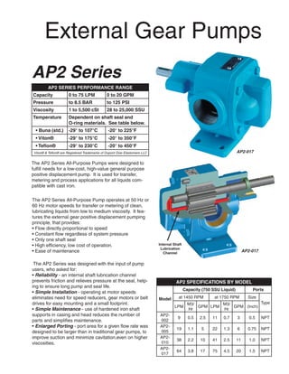
1. External Gear Pumps
AP2 Series
AP2 SERIES PERFORMANCE RANGE
Capacity 0 to 75 LPM 0 to 20 GPM
Pressure to 8.5 BAR to 125 PSI
Viscosity 1 to 5,500 cSt 28 to 25,000 SSU
Temperature Dependent on shaft seal and
O-ring materials. See table below.
• Buna (std.) -29° to 107°C -20° to 225°F
• Viton® -29° to 175°C -20° to 350°F
• Teflon® -29° to 230°C -20° to 450°F
Viton® & Teflon® are Registered Trademarks of Dupont Dow Elastomers LLC AP2-017
The AP2 Series All-Purpose Pumps were designed to
fulfill needs for a low-cost, high-value general purpose
positive displacement pump. It is used for transfer,
metering and process applications for all liquids com-
patible with cast iron.
The AP2 Series All-Purpose Pump operates at 50 Hz or
60 Hz motor speeds for transfer or metering of clean,
lubricating liquids from low to medium viscosity. It fea-
tures the external gear positive displacement pumping
principle, that provides:
• Flow directly proportional to speed
• Constant flow regardless of system pressure
• Only one shaft seal
• High efficiency, low cost of operation. Internal Shaft
Lubrication
• Ease of maintenance Channel
AP2-017
The AP2 Series was designed with the input of pump
users, who asked for:
• Reliability - an internal shaft lubrication channel
prevents friction and relieves pressure at the seal, help- AP2 SPECIFICATIONS BY MODEL
ing to ensure long pump and seal life.
Capacity (750 SSU Liquid) Ports
• Simple Installation - operating at motor speeds
eliminates need for speed reducers, gear motors or belt Model at 1450 RPMat 1750 RPM Size
drives for easy mounting and a small footprint. M3/ M3/ Type
LPM GPM LPM GPM (Inch)
• Simple Maintenance - use of hardened iron shaft Hr Hr
supports in casing and head reduces the number of AP2-
9 0.5 2.5 11 0.7 3 0.5 NPT
parts and simplifies maintenance. 002
• Enlarged Porting - port area for a given flow rate was AP2-
19 1.1 5 22 1.3 6 0.75 NPT
designed to be larger than in traditional gear pumps, to 005
improve suction and minimize cavitation,even on higher AP2-
38 2.2 10 41 2.5 11 1.0 NPT
viscosities. 010
AP2-
64 3.8 17 75 4.5 20 1.5 NPT
017
2. Pump Selection
1. Information required to select pump: flow rate, system pressure, motor speed and viscosity of fluid.
2. On Chart 1, “AP2 Series Capacities” performance curves, select the pump that most closely matches
flow requirements. Two curves are provided for each pump, one at 3 cSt and one at 165 cSt. Pefor-
mance between 165 cSt and higher viscosities is virtually identical.
3. On Chart 2, “AP2 Series Motor Selection Chart” below, first find the row for the selected pump and mo-
tor speed, then locate the viscosity and pressure column to determine required motor kW (HP).
4. Optional carbon graphite bushings (available only with mechanical seal option) should be used below 4
cSt (38 SSU) viscosity.
Chart 1 ��� ������ ���������� �� ��� ��� ���� ���� ��������� ��������
����������� ����� ������� ��� ��� ��� ���� ���� ����
����
��
��
�������
��
�������� � �� ������� ��� ������
��� ��� ���� ���� ��
����
�������� � ������ ��� ������
� ��� ��� ����
�� ��
��
��
��
�� ������� ��
�� �
�
�� �������
�
��
������� �
� �
� ��� ���� ���� ����
����� � ���
Chart 2 AP2 Series Motor Selection Chart
Viscosity - cSt (SSU) 3 (38) 20 (100) 165 (750) 550 (2,500) 1650 (7,500) 5,500 (25,000)
Pressure - Bar (PSI) 3.4 8.6 3.4 8.6 3.4 8.6 3.4 8.6 3.4 8.6 3.4 8.6
(50) (125) (50) (125) (50) (125) (50) (125) (50) (125) (50) (125)
Pump Motor RPM
1450 .25 (.33) .37 (.50) .25 (.33) .37 (.50) .25 (.33) .37 (.50) .37 (.50) .37 (.50) .56 (.75) .56 (.75) .75 (1.0) .75 (1.0)
AP2- kW
002 (HP)
1750 .25 (.33) .37 (.50) .37 (.50) .37 (.50) .37 (.50) .37 (.50) .56 (.75) .56 (.75) .75 (1.0) .75 (1.0) 1.1 (1.5) 1.1 (1.5)
1450 .56 (.75) .56 (.75) .56 (.75) .56 (.75) .56 (.75) .56 (.75) .75 (1.0) .75 (1.0) 1.1 (1.5) 1.1 (1.5) 1.1 (1.5) 1.5 (2.0)
AP2- kW
005 (HP)
1750 .56 (.75) .75 (1.0) .75 (1.0) .75 (1.0) .56 (.75) .75 (1.0) .75 (1.0) 1.1 (1.5) 1.1 (1.5) 1.5 (2.0) 1.5 (2.0) 2.2 (3.0)
1450 .56 (.75) .75 (1.0) .56 (.75) 1.1 (1.5) .75 (1.0) .75 (1.0) 1.5 (2.0) 1.5 (2.0) 1.5 (2.0) 1.5 (2.0) 2.2 (3.0) 3.7 (5.0)
AP2- kW
010 (HP)
1750 .75 (1.0) .75 (1.0) .56 (.75) 1.5 (2.0) .75 (1.0) .75 (1.0) 1.5 (2.0) 1.5 (2.0) 1.5 (2.0) 1.5 (2.0) 2.2 (3.0) 3.7 (5.0)
1450 .75 (1.0) 1.1 (1.5) .75 (1.0) 1.5 (2.0) 1.1 (1.5) 1.5 (2.0) 1.5 (2.0) 2.2 (3.0) 2.2 (3.0) 2.2 (3.0) 2.2 (3.0) 3.7 (5.0)
AP2- kW
017 (HP)
1750 .75 (1.0) 1.5 (2.0) .75 (1.0) 2.2 (3.0) 1.5 (2.0) 2.2 (3.0) 2.2 (3.0) 2.2 (3.0) 2.2 (3.0) 3.7 (5.0) 3.7 (5.0) 3.7 (5.0)
Contact representative for recommendations on operating speed and motor sizing on viscosities greater than 5,500 cSt (25,000 SSU).
3. AP2-002 AP2-017 with Optional Relief Valve
Dimensions
Model A Units B C D E F* H J* L M O R S T U V
AP2- N/A mm 63.5 121.4 82.0 50.8 N/A 144.8 10.7 191.3 138.7 9.9 223.0 9.9 31.5 15.88 4.76 SQ X 19.1 LONG
002
.50 NPT inch 2.50 4.78 3.23 2.00 N/A 5.70 0.42 7.53 5.46 0.39 8.78 0.39 1.24 0.625 .19 SQ X .75 LONG
AP2- N/A mm 63.5 129.0 82.0 50.8 N/A 144.8 10.7 199.1 138.7 9.9 230.9 9.9 31.5 15.88 4.76 SQ X 19.1 LONG
005
.75 NPT inch 2.50 5.08 3.23 2.00 N/A 5.70 0.42 7.84 5.46 0.39 9.09 0.39 1.24 0.625 .19 SQ X .75 LONG
AP2- N/A mm 63.5 138.7 82.0 50.8 25.4 144.8 10.7 214.9 138.7 9.9 246.6 9.9 31.5 15.88 4.76 SQ X 19.1 LONG
010
1.00 NPT inch 2.50 5.46 3.23 2.00 1.00 5.70 0.42 8.46 5.46 0.39 9.71 0.39 1.24 0.625 .19 SQ X .75 LONG
AP2- N/A mm 63.5 152.7 82.0 50.8 47.8 144.8 10.7 237.0 138.7 9.9 268.7 9.9 31.5 15.88 4.76 SQ X 19.1 LONG
017
1.50 NPT inch 2.50 6.01 3.23 2.00 1.88 5.70 0.42 9.33 5.46 0.39 10.58 0.39 1.24 0.625 .19 SQ X .75 LONG
* NOTE: AP2-002 and AP2-005 have 2 mounting holes and AP2-010 and AP2-017 have 4 mounting holes.
4. Construction
STANDARD
PART OPTIONS
CONSTRUCTION
Casing Iron —
Head Iron, no relief valve • Iron, with integral relief valve (fixed 8.5 bar/125 psi setting)
Shafts Hardened Steel —
Gears Hardened Steel —
• Viton
O-Rings Buna • Teflon
• Packing [rated to 230°C (450°F)]
• Viton Lip Seal
Shaft Seal Buna Lip Seal • Teflon Lip Seal
• Carbon/Ceramic Mechanical Seal with either Buna or Viton
Elastomers
Hardened Iron Shaft
Shaft Support • Carbon Graphite Bushings (only available with Mechanical Seal option)
Supports
Additional AP Pump Sizes
AP Pump Nominal Capacity by Series
There are four series of 950 RPM 1150 RPM 1450 RPM 1750 RPM
AP pumps, with several Series
LPM M3/hr GPM LPM M3/hr GPM LPM M3/hr GPM LPM M3/hr GPM
sizes in each series. See AP2 42 2.5 11 51 3.0 13 64 3.8 17 77 4.6 20
chart at right or envelope AP3 124 7.4 32 150 9.0 39 189 11 50 228 13.7 60
curve below for series AP4 310 18.6 82 375 22.5 99 473 28 125 - - -
selection. AP5 1135 68 300 1373 82 363 - - - - - -
AP Pump Performance Envelope
�������� �������� ��� �������
� � � �� �� �� �� �� �� ��� ��� ��� ��� ���
�
���
�
�������� �����
�������� �����
� ���
�������
�������
�������
�������
�������
�������
�������
�������
�������
�������
�������
�������
�������
�
� ��
�
� ��
�
�
����� ���� ����� ���� ����� ���� ��
� �
� �� �� �� �� ��� ��� ��� ��� ��� ��� ��� ��� ����
�������� ������� ��� �������
A Unit of
406 State Street, Cedar Falls, IA 50613 USA
Form N0. 902 Tel 1-319-266-1741 Fax 1-319-273-8157
5. External Gear Pumps
AP3 Series
AP3 SERIES PERFORMANCE RANGE
Capacity 0 to 228 LPM 0 to 60 GPM
Pressure to 8.5 BAR to 125 PSI
Viscosity 1 to 5,500 cSt 28 to 25,000 SSU
Temperature Dependent on shaft seal and
O-ring materials. See table below.
• Buna (std.) -29° to 107°C -20° to 225°F
• Viton® -29° to 175°C -20° to 350°F
• Teflon® -29° to 230°C -20° to 450°F
Viton® & Teflon® are Registered Trademarks of Dupont Dow Elastomers LLC
The AP3 Series All-Purpose Pumps were designed to
fulfill needs for a low-cost, high-value general purpose
positive displacement pump. It is used for transfer,
metering and process applications for all liquids com-
patible with cast iron.
The AP3 Series All-Purpose Pump operates at 50 Hz or
60 Hz motor speeds for transfer or metering of clean,
lubricating liquids from low to medium viscosity. It fea-
tures the external gear positive displacement pumping
principle, that provides: Internal Shaft
Lubrication
• Flow directly proportional to speed Channel AP3-050
• Constant flow regardless of system pressure
• Only one shaft seal
• High efficiency, low cost of operation.
• Ease of maintenance
The AP3 Series was designed with the input of pump
users, who asked for:
• Reliability - an internal shaft lubrication channel
prevents friction and relieves pressure at the seal, help- AP3 SPECIFICATIONS BY MODEL
ing to ensure long pump and seal life.
Capacity (750 SSU Liquid) Ports
• Simple Installation - operating at motor speeds
eliminates need for speed reducers, gear motors or belt Model at 1450 RPM at 1750 RPM Size
drives for easy mounting and a small footprint. M3/ M3/ Type
LPM GPM LPM GPM (Inch)
• Simple Maintenance - use of hardened iron shaft Hr Hr
supports in casing and head reduces the number of AP3-
91 5.5 24 110 6.6 29 1.5 NPT
parts and simplifies maintenance. 024
• Enlarged Porting - port area for a given flow rate was AP2-
132 7.9 35 159 9.5 42 2.0 Flange
designed to be larger than in traditional gear pumps, to 035
improve suction and minimize cavitation,even on higher AP2-
189 11 50 228 13.7 60 2.5 Flange
viscosities. 050
6. Pump Selection
1. Information required to select pump: flow rate, system pressure, motor speed and viscosity of fluid.
2. On Chart 1, “AP3 Series Capacities” performance curves, select the pump that most closely matches
flow requirements. Two curves are provided for each pump, one at 3 cSt and one at 165 cSt. Pefor-
mance between 165 cSt and higher viscosities is virtually identical.
3. On Chart 2, “AP3 Series Motor Selection Chart” below, first find the row for the selected pump and mo-
tor speed, then locate the viscosity and pressure column to determine required motor kW (HP).
4. Optional carbon graphite bushings (available only with mechanical seal option) should be used below 4
cSt (38 SSU) viscosity.
Chart 1 ��� ������ ���������� �� ��� ��� ���� ���� ��������� ��������
����������� ����� ������� ��� ��� ��� ���� ���� ����
����
���
��
��� �������
�������� � �� ������� ��� ������
��� ��� ���� ����
����
�������� � ������ ��� ������
� ��� ��� ���� ��
���
��� ��
�������
���
��
�� �������
��
��
��
��
� �
� ��� ���� ���� ����
����� � ���
Chart 2 AP3 Series Motor Selection Chart
Viscosity - cSt
3 (38) 20 (100) 165 (750) 550 (2,500) 1650 (7,500) 5,500 (25,000)
(SSU)
Pressure - Bar (PSI) 3.4 8.6 3.4 8.6 3.4 8.6 3.4 8.6 3.4 8.6 3.4 8.6
Pump Motor RPM (50) (125) (50) (125) (50) (125) (50) (125) (50) (125) (50) (125)
AP3- kW 1450 1.5 (2.0) 1.5 (2.0) 1.5 (2.0) 1.5 (2.0) 1.5 (2.0) 2.2 (3.0) 2.2 (3.0) 2.2 (3.0) 3.7 (5.0) 3.7 (5.0) 3.7 (5.0) 3.7 (5.0)
024 (HP) 1750 1.5 (2.0) 2.2 (3.0) 1.5 (2.0) 2.2 (3.0) 2.2 (3.0) 2.2 (3.0) 2.2 (3.0) 3.7 (5.0) 3.7 (5.0) 3.7 (5.0) 3.7 (5.0) 5.6 (7.5)
AP3- kW 1450 2.2 (3.0) 2.2 (3.0) 2.2 (3.0) 2.2 (3.0) 2.2 (3.0) 3.7 (5.0) 3.7 (5.0) 3.7 (5.0) 3.7 (5.0) 5.6 (7.5) 5.6 (7.5) 7.5 (10)
035 (HP) 1750 2.2 (3.0) 3.7 (5.0) 2.2 (3.0) 3.7 (5.0) 2.2 (3.0) 3.7 (5.0) 3.7 (5.0) 5.6 (7.5) 5.6 (7.5) 7.5 (10) 7.5 (10) 7.5 (10)
AP3- kW 1450 2.2 (3.0) 3.7 (5.0) 2.2 (3.0) 3.7 (5.0) 3.7 (5.0) 5.6 (7.5) 3.7 (5.0) 5.6 (7.5) 3.7 (5.0) 5.6 (7.5) 7.5 (10) 11 (15)
050 (HP) 1750 2.2 (3.0) 3.7 (5.0) 2.2 (3.0) 5.6 (7.5) 3.7 (5.0) 5.6 (7.5) 5.6 (7.5) 5.6 (7.5) 5.6 (7.5) 7.5 (10) 7.5 (10) 11 (15)
Contact representative for recommendations on operating speed and motor sizing on viscosities greater than 5,500 cSt (25,000 SSU).
7. AP3-024 AP3-050 with
Optional Relief
Valve
Dimensions
AP3-024
(NPT Ports)
AP3-024
and AP3-035
(Flange**
Ports)
Model Dim. A** B C D E F* H J* L M O R S T U V
AP3- mm N/A 76.2 179.6 108.5 57.2 N/A 186.2 9.9 277.9 188.7 15.0 345.4 125.7 49.3 25.40 6.35 SQ X 31.8 LONG
024 in. 1.50 NPT 3.00 7.07 4.27 2.25 N/A 7.33 0.39 10.94 7.43 0.59 13.60 4.95 1.94 1.000 .25 SQ X 1.25 LONG
AP3- mm N/A 108.0 194.6 108.5 57.2 N/A 191.0 9.9 295.7 188.7 15.0 363.2 125.7 49.3 25.40 6.35 SQ X 31.8 LONG
035 in 2.0 Flange 4.25 7.66 4.27 2.25 N/A 7.52 0.39 11.64 7.43 0.59 14.30 4.95 1.94 1.000 .25 SQ X 1.25 LONG
AP3- mm N/A 108.0 213.6 108.5 57.2 44.5 200.9 9.9 319.8 188.7 15.0 387.4 125.7 49.3 25.40 4.76 SQ X 19.1 LONG
050 in 2.5 Flange 4.25 8.41 4.27 2.25 1.75 7.91 0.39 12.59 7.43 0.59 15.25 4.95 1.94 1.000 6.35 SQ X 31.8 LONG
* Note: AP3-024 and AP3-035 have (2) mounting holes and AP3-050 has (4) mounting holes.
** Note: Flange ports are suitable for use with 125# ANSI cast iron companion flanges or flange fittings
8. Construction
STANDARD
PART OPTIONS
CONSTRUCTION
Casing Iron —
Head Iron, no relief valve • Iron, with integral relief valve (fixed 8.5 bar/125 psi setting)
Shafts Hardened Steel —
Gears Hardened Steel —
• Viton
O-Rings Buna • Teflon
• Packing [rated to 230°C (450°F)]
• Viton Lip Seal
Shaft Seal Buna Lip Seal • Teflon Lip Seal
• Carbon/Ceramic Mechanical Seal with either Buna or Viton
Elastomers
Hardened Iron Shaft
Shaft Support • Carbon Graphite Bushings (only available with Mechanical Seal option)
Supports
Additional AP Pump Sizes
AP Pump Nominal Capacity by Series
There are four series of 950 RPM 1150 RPM 1450 RPM 1750 RPM
AP pumps, with several Series
LPM M3/hr GPM LPM M3/hr GPM LPM M3/hr GPM LPM M3/hr GPM
sizes in each series. See AP2 42 2.5 11 51 3.0 13 64 3.8 17 77 4.6 20
chart at right or envelope AP3 124 7.4 32 150 9.0 39 189 11 50 228 13.7 60
curve below for series AP4 310 18.6 82 375 22.5 99 473 28 125 - - -
selection. AP5 1135 68 300 1373 82 363 - - - - - -
AP Pump Performance Envelope
�������� �������� ��� �������
� � � �� �� �� �� �� �� ��� ��� ��� ��� ���
�
���
�
�������� �����
�������� �����
� ���
�������
�������
�������
�������
�������
�������
�������
�������
�������
�������
�������
�������
�������
�
� ��
�
� ��
�
�
����� ���� ����� ���� ����� ���� ��
� �
� �� �� �� �� ��� ��� ��� ��� ��� ��� ��� ��� ����
�������� ������� ��� �������
A Unit of
406 State Street, Cedar Falls, IA 50613 USA
Form N0. 903 Tel 1-319-266-1741 Fax 1-319-273-8157