1. TM
HALO Turbo Charger
For Reverse Osmosis Systems
Installation, Operation and Maintenance Manual
Definitions Feed: the water before it enters the membrane
Permeate: the purified water exiting the membrane
Brine: the concentrate water exiting the membrane
Feed Pump: the pump that develops the high pressure in the feed
TURBO: Hydraulic TurboCharger energy recovery device.
Introduction Features
The HALO TurboCharger or TURBO is designed to The TURBO incorporates a number of features
produce a pressure boost in RO feed streams using designed to insure simple operation and long
the hydraulic energy in the brine stream. operating life.
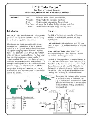
The diagram and the corresponding table below Low Maintenance -No mechanical seals. No need
show how the TURBO works as a feed pressure for oil or grease. The pumpage provides all required
booster in an RO system. Low pressure feed passes lubrication.
through the feed pump which provides a pressure Brine Pressure Control - The TURBO can
boost. The feed water passes through the TURBO discharge brine against a back pressure. The unit
which provides an additional boost. The feed water never needs a brine disposal pump.
then enters the membrane pressure vessels. A
percentage of the feed water exits the membrane as The TURBO is equipped with two external tubes or
permeate. The rest exits as high pressure brine. The lines. One tube runs from the brine inlet passage to
brine passes through the TURBO which extracts the the turbine body. This tube contains a valve, called
pressure energy. The brine leaves the TURBO at the auxiliary nozzle valve (ANV). The ANV allows
low pressure for disposal. Note that the TURBO the operator to adjust the brine flow and pressure.
eliminates the brine pressure control valve normally The auxiliary brine nozzle valve is described in the
used in RO systems. “Starting and Operating”section of this manual.
The second line connects drilled passages
to the thrust bearing in the turbine end
cap to the feed inlet passage of the Turbo.
This line provides water to pressurize the
hydrostatic thrust bearing located in the
turbine end cap.
Flow (gpm) Pressure (psi)
1 300 30
2 300 650
3 300 1000
4 180 970
5 180 5