6.4.2.4 calculating and configuring an i pv6 route summarization instructions
•
0 likes•292 views

summarization

Recommended
More Related Content
Viewers also liked
Viewers also liked (12)
Similar to 6.4.2.4 calculating and configuring an i pv6 route summarization instructions
Similar to 6.4.2.4 calculating and configuring an i pv6 route summarization instructions (20)
Recently uploaded
Recently uploaded (20)
6.4.2.4 calculating and configuring an i pv6 route summarization instructions
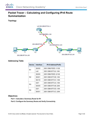
- 1. © 2013 Cisco and/or its affiliates. All rights reserved. This document is Cisco Public. Page 1 of 2 Packet Tracer – Calculating and Configuring IPv6 Route Summarization Topology Addressing Table Device Interface IPv6 Address/Prefix R1 S0/0/0 2001:DB8:FEED::1/126 Lo0 2001:DB8:5F73:6::1/64 R2 S0/0/0 2001:DB8:FEED::2/126 S0/0/1 2001:DB8:5F73:B::1/64 S0/1/0 2001:DB8:5F73:C::1/64 R3 G0/1 2001:DB8:5F73:A::1/64 S0/0/0 2001:DB8:5F73:B::2/64 R4 G0/1 2001:DB8:5F73:D::1/64 S0/0/1 2001:DB8:5F73:C::2/64 Objectives Part 1: Calculate a Summary Route for R1 Part 2: Configure the Summary Route and Verify Connectivity
- 2. Packet Tracer - Configuring IPv6 Route Summarization © 2013 Cisco and/or its affiliates. All rights reserved. This document is Cisco Public. Page 2 of 2 Background In this activity, you will calculate, configure and verify a summary route for all the networks R1 can access through R2. R1 is configured with a loopback interface. Instead of adding a LAN or another network to R1, use a loopback interface to simplify testing when verifying routing. Part 1: Calculate a Summary Route for R1 When summarizing an IPv6 address, look at the prefix to determine where the address ends. In this case, a /64 ends at the fourth segment. a. List the first four segments of each of the networks. Because the first three segments have the identical hexadecimal digits, there is no need to write them in binary. The fourth segment is different (:A, :B, :C, and :D); therefore, write the 16 bits for each in binary. Count the left-most matching bits to determine the prefix for the summary route. 2001:DB8:5F73:0000000000001010 2001:DB8:5F73:0000000000001011 2001:DB8:5F73:0000000000001100 2001:DB8:5F73:0000000000001101 b. In the fourth segment, the network addresses have the first 13 bits in common. Therefore, the summarized prefix is the 48 bits from the first three segments, plus the 13 bit from the fourth segment (or /61). c. Copy the matching bits and fill in the remaining bits with zeros to determine that the summarized network address is 2001:0DB8:5F73:8::/61. Part 2: Configure the Summary Route and Verify Connectivity a. Configure a directly attached summary route on R1. b. PC1 should be able to ping PC2. c. PC1 and PC2 should both be able to ping the Loopback 0 interface on R1.