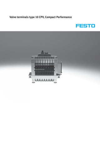
2. Valve terminals type 10 CPV, Compact Performance
Features
Innovative Versatile Reliable Easy to mount
• Cubic design for exceptional • Flexible and cost-effective • LED displays • Ready to install unit, already
performance and low weight connection of 2 to 8 valve slices • Manual valve overrides assembled and tested
• Low installation and bus • Highly flexible thanks to: • Protection class to IP65 • Lower cost of selection, ordering,
connection costs – various pneumatic functions • CE symbol installation and commissioning
• Ideal for decentralised machines (valve variants) • ATEX certification • Secure mounting on wall or H-rail
and system structures, for example – different pressure ranges (see Technical Data) mounting
– in handling technology – vacuum switches • Pneumatic multiple connector plate
– in conveyor technology – integrated vacuum generation – fast assembly without the need to
– in the packaging industry – relay plates with floating replace the connected tubing
– in sorting systems electrical outputs • Assembly optimised for control
– in upstream machine functions • Separator plates for the formation cabinets
• Integrated diagnostics, condition of pressure zones
monitoring (Fieldbus Direct) • Valves with integrated separation of
• A string extension for Fieldbus channels 1 and 11
Direct of 8 … 32 inputs and • Blanking plates for future
8 … 32 outputs is possible without expansion
any difficulty (version-dependent)
2 Internet: www.festo.com/catalogue/... Subject to change – 2008/10
3. Valve terminals type 10 CPV, Compact Performance
Features
Simple electrical connections: Inscription labels
– Individual connection/
ET200X/ET200pro
– Multi-pin plug connector
– AS-interface
– Installation system CP/CPI
– Fieldbus Direct Reduced downtimes:
Operating voltage connection LED diagnosis on the spot
Quick mounting: Reliable operation:
– Directly using screws Manual override, non-detenting, detenting
– On a H-rail or blocked
– Via the pneumatic multiple
connector plate Comprehensive range of valve functions,
pressure zone formation, blanking plates
Robust metal thread or pre-
assembled QS connections
Width
– 10 mm
– 14 mm
– 18 mm
Equipment options
Valve functions
• 5/2-way valve, single solenoid • 2x 3/2-way valve, normally open • 5/3-way valve, mid-position closed • Vacuum generator
• 5/2-way valve (with channel • 2x 3/2-way valves (with channel • 2x 2/2-way valve, normally closed • Vacuum generator and 2/2-way
separation 1, 11), single solenoid separation 1, 11), normally open • 2x 2/2-way valve (with channel valve with ejector pulse
• 5/2-way valve, single solenoid, • 2x 3/2-way valve, 1x normally separation 1, 11), normally closed • Certain terminals allow the choice
fast-switching open, 1x closed • 2x 2/2-way valve, 1x normally of a relay plate with two floating
• 5/2-way valve, double solenoid • 2x 3/2-way valve (with channel open, 1x closed contacts in place of a valve sub-
• 5/2-way valve (with channel separation 1, 11) 1x normally • 2x 2/2-way valve (with channel base
separation 1, 11), double-solenoid open, 1x closed separation 1, 11) 1x normally
• 2x 3/2-way valve, normally closed • 2x 3/2-way valve, normally closed, open, 1x closed
• 2x 3/2-way valves (with channel integrated back pressure protection
separation 1, 11), normally closed
Special features
Individual connection Multi-pin plug connection AS-interface Installation system CP/CPI
• 2 … 8 valve positions, • 4, 6 or 8 valve positions, • 2, 4 or 8 valve positions, • 4, 6 or 8 valve positions,
max. 16 solenoid coils max. 16 solenoid coils max. 8 solenoid coils max. 16 solenoid coils
• 4 or 8 inputs for 4 or 8 valve • With CP/CPI string extension,
positions further valve terminals and I/O
modules with CP/CPI function can
be connected
Fieldbus Direct Electrical connection for ET200X/ET200pro
• 8 valve positions,
max. 16 solenoid coils
• 8 valve positions,
max. 16 solenoid coils
-H- Note
• With CP/CPI string extension, A moulded seal is required for the The moulded seal CPV10-..-GE-8
further valve terminals and I/O valve terminal CPV10-ET 200pro in or CPV14-..-GE-8 must be ordered
modules with CP/CPI functions can order to achieve the IP protection separately.
be connected class.
2008/10 – Subject to change Internet: www.festo.com/catalogue/... 3
4. Valve terminals type 10 CPV, Compact Performance
Features
Valve terminal configurator Online via: www.festo.com
A valve terminal configurator is avai-
lable to help you select a suitable
valve terminal CPV. This makes it
much easier for you to find the right
product.
The valve terminals are fully as-
sembled according to your order
specifications and individually tested.
This reduces assembly and
installation time to a minimum.
You order a valve terminal type 10
using the order code.
Ordering system for type 10
Internet: type 10
The illustration above provides an Once you have called up Here you can enter a “Part No.” You can then configure the valve ter-
example of a valve terminal www.festo.com, select the online ver- (e.g. 18210), “Type” (e.g. CPV14) or minal step by step (from left to right)
configuration. sion of the digital product catalogue “Article Designation” (e.g. valve according to your requirements.
The following steps explain how you from the “Products” submenu. Acti- terminal) to find the valve terminal Click on the shopping basket to save
arrive at the order code: vate the “Direct Search” menu. you want. Click on the link “Configure the selected configuration (this does
common options”. not trigger an order).
You can switch to expert mode at any
time by clicking on the “Further
options” link.
This provides you with extended
options for configuring your valve
terminal.
2D/3D CAD data Online via: www.festo.com
You can request the CAD data for a (compass). On the next screen you can
valve terminal you have configured. To generate a 3D preview or request
do this, perform the product search as another data format of your choice by
described above. Enter the shopping e-mail.
basket and click on the CAD icon
4 Internet: www.festo.com/catalogue/... Subject to change – 2008/10
5. Valve terminals type 10 CPV, Compact Performance
Features
Electrical connections
Individual connection
Connection is independent of the con- It also features a built-in current re- An intrinsically safe version rounds off
trol technology used. This ensures cor- duction circuit. Individual connection the range.
rect polarity during installation. The permits the selection of 2 to 16 sole- Further information
connector plug is equipped with an noid coils (divided between two to Internet: type 10 CPV10-EX-VI
LED which indicates switching status, eight valve slices, including in uneven
and an overvoltage protective circuit. stages).
Multi-pin plug connection
Control signals from the controller to tion time. The current reduction circuit This valve terminal can be equipped
the valve terminal are transmitted via for the valves is also integrated in the with 4 to 16 solenoid coils (4, 6 or
a pre-assembled multi-wire cable, multi-pin plug connection. 8 valve slices).
which substantially reduces installa-
AS-interface connection
A special feature of the AS-interface is The valve terminal with AS-interface • With four or eight inputs and four or
its ability to simultaneously transmit can be configured as follows: eight valve slices incl. vacant posi-
data and supply power via a two-wire • Without inputs, with two or four tion or positions (max. 6 solenoid
cable. The encoded cable profile valve slices (max. 4 solenoid coils) coils for A/B operation to SPEC.2.1)
prevents connection with incorrect and additional power supply and additional power supply. In A/B
polarity. If the valves have to be • With four inputs and four valve operation to SPEC. 3.0 with profile
disconnected from mains power in an slices (max. 8 solenoid coils) 7.A.7 eight solenoid coils can be
emergency, they can also be supplied • With four or eight inputs and four or connected in contrast to the SPEC
with electrical power via a separate eight valve slices (max. 8 solenoid 2.1 version.
connection. Two versions are avail- coils) and additional power supply
able for valve terminals for A/B Further information
operation. Internet: as-interface
-H- Note
Valve terminals to SPEC.2.1 cannot
be operated on a master to
SPEC.3.0 with profile 7.A.7.
2008/10 – Subject to change Internet: www.festo.com/catalogue/... 5
6. Valve terminals type 10 CPV, Compact Performance
Features
Electrical connections
Installation system CP/CPI
Valve terminals with fieldbus connec- Four strings with up to 32 inputs and
tion are intended for connection to 32 outputs (version-dependent) can
higher-order fieldbus nodes or to con- be connected to a fieldbus node or
trol blocks. A fieldbus node or control control block. The CPV valve terminal
block also enables the connection of is treated like an output module with
decentralised input/output modules. up to 8 outputs (4, 6 or 8 valve slices
The following fieldbus protocols are or 4 to 16 solenoid coils per
supported: terminal). The connecting cables
• Festo fieldbus, ABB CS31, Moeller transmit all required electrical signals
Suconet K (control signals, operating voltage for
• Interbus the internal electronics of the module
• Allen Bradley (1771 RIO) and load voltage supply for connected
• DeviceNet valves).
• Profibus-DP
• CANopen Further information
• CC-Link Internet: cpi
Fieldbus Direct
Fieldbus Fieldbus Direct is a system for the The new high-performance CPI string
compact connection of a CPV, CPV-SC, extension offers up to 4 supplemen-
CPA-SC or CDVI valve terminal to tary CPI modules, combined with CP or
different fieldbus standards such as CPI-compatible valve terminals for ex-
Profibus and DeviceNet. tension purposes. An expansion of the
The fieldbus node is directly inte- system, Fieldbus Direct of 8 … 32 in-
grated in the electrical interface of the puts and 8 … 32 outputs is possible
valve terminal and therefore takes up without any difficulty.
only a minimal amount of space. The
CPI string extension option allows the
functions and components of the CPI
system to be used.
ET200X/ET200pro pneumatic interface for CPV10 and CPV14
Adaptation of the CPV valve terminal • 8 valve slices for up to 16 CPV
to the input/output module valves
ET200X/ET200pro from Siemens: • Fast and secure contacting to IP65
The combination of the • CPV10 and CPV14 valve terminals
ET200X/ET200pro functional modules • Not permitted for CPV10-EX-VI
and the pneumatic functions of the • High degree of protection
CPV valve terminal provides a highly IP65/IP67
integrateable automation solution for • Modular design
systems using electrical and pneu-
matic drives with:
6 Internet: www.festo.com/catalogue/... Subject to change – 2008/10
7. Valve terminals type 10 CPV, Compact Performance
Peripherals overview
CPV – The benefits at a glance
The CPV valve terminal is of unique performance and are also extremely sacrificed in favour of compactness. contributes to the safe operation of
design. It provides the flexible com- compact. Two functions per valve slice The connecting thread and mounting the valve terminal.
bination of pneumatic performance, (e.g. 2x 3/2-way valves) mean that attachments are metallic. A particular plus is the range of
electrical connection technologies and twice the component density can be The manual override for the valves can electrical connection technologies
a wide range of mounting options. achieved. This saves space and be adapted for different operating supported. All types of valve actuation
The generously sized flow ducts and reduces costs. situations. If, for example, a detenting are possible, from individual valve
powerful flat plate silencers ensure The cubic design permits exceptional manual override is required for connections up to bus systems with
high flow rates. This means that even performance yet a comparatively low setting-up mode, the manual override versatile expansion options. The
comparatively large pneumatic weight. The benefits of this design are can be easily converted for that integration of electrical input and
cylinders can be driven with ease. obvious when the valve terminal is application in a way that rules out output modules permits cost-effective
All valves are in the form of valve used on a moving installation. operational errors. solutions within the different
slices. They are optimised for flow However robustness must not be The clear, large labelling system also installation concepts.
The design principle
The cubic design provides a clearly An optional inscription label holder • Compressed air supply connections • Manual operation/identification on
assigned function on each face. Thus, can be placed on the front of the valve on the left, right or underneath the front
for example, the electrical connection terminal. • Pneumatic working ports and func- • Electrical connection surface on the
is mounted on the top face. The different combination options tional modules (vertical linkage) top
ensure the optimum solution for the underneath • Mounting surface at the back or
task at hand. even at the front via a pneumatic
multiple connector plate
2008/10 – Subject to change Internet: www.festo.com/catalogue/... 7
8. Valve terminals type 10 CPV, Compact Performance
Peripherals overview
Overview – CPV valve terminal
1
aC
aB 2
3
aA
4
5
6
7
aJ 9 8
1 Basic electrical unit (Fieldbus 3 Comprehensive range of valve 7 Functional module aJ Left-hand end plate with flat
Direct, CP/CPI installation functions (vertical linkage) plate silencer
system, AS-interface, multi-pin 4 Right-hand end plate (threaded 8 Pneumatic multiple connector aA H-rail mounting
plug, individual connection) connection not in conjunction plate aB Wall mounting
2 Right-hand end plate with flat with pneumatic multiple 9 Left-hand end plate (threaded aC Plug socket with cable for
plate silencer connector plate) connection not in conjunction individual connection
5 Holder for inscription label with pneumatic multiple
6 QS push-in fittings connector plate)
8 Internet: www.festo.com/catalogue/... Subject to change – 2008/10
9. Valve terminals type 10 CPV, Compact Performance
Key features – Pneumatic components
Valves
CPV valves are series manifold valves, and allow a direct flow of air through piston spool system with a patented functions are always identical for all
i.e. in addition to the valve function the valve slices. sealing principle that guarantees its actuator types. Most functions are
they contain all of the pneumatic This helps achieve maximum flow suitability for a wide range of applica- also available in the various valve
ducts for supply, exhaust and the rates. All valves have a pneumatic tions as well as a long service life. sizes (spacing). Restrictions are noted
working lines. The supply ducts are a pilot control for optimising perform- The pneumatic components and where applicable.
central component of the valve slices ance. The valve function is based on a
Valve function
Code Circuit symbol
y Size Description
p
10 14 18
M 5/2-way valve, single solenoid
• Pneumatic spring return
• Piston spool valve
MK 5/2-way valve, single solenoid
• With channel separation 1, 11
–
• Pneumatic spring return
• Piston spool valve
F 5/2-way valve, single solenoid
• Pneumatic spring return
– –
• Piston spool valve
• Fast switching
J 5/2-way valve, double solenoid
• Piston spool valve
JK 5/2-way valve, double solenoid
• With channel separation 1, 11
–
• Piston spool valve
C 2x 3/2-way valve, single solenoid
• Normally closed
• Pneumatic spring return
• Piston spool valve
CK 2x 3/2-way valve, single solenoid
• With channel separation 1, 11
– • Normally closed
• Pneumatic spring return
• Piston spool valve
CY 2x 3/2-way valve, single solenoid
• Normally closed
• Pneumatic spring return
• Integrated back pressure protection
• Piston spool valve
– – • Not suitable for vacuum
-H- Note
If it is necessary to ensure that the back pressure flaps are closed securely in
the event of a sudden drop in operating pressure or if the operating pressure is
switched off, the valve terminal must be operated with external pilot air supply.
2008/10 – Subject to change Internet: www.festo.com/catalogue/... 9
10. Valve terminals type 10 CPV, Compact Performance
Key features – Pneumatic components
Valve function
Code Circuit symbol
y Size Description
p
10 14 18
N 2x 3/2-way valve, single solenoid
• Normally open
• Pneumatic spring return
• The function of a 5/3-way valve in mid-position pressurized can be
implemented with these valves in basic position open.
• Piston spool valve
NK 2x 3/2-way valve, single solenoid
• With channel separation 1, 11
• Normally open
– • Pneumatic spring return
• The function of a 5/3-way valve in mid-position pressurized can be
implemented with these valves in basic position open.
• Piston spool valve
H 2x 3/2-way valve, single solenoid
• Normally
1x open (pilot control 12)
1x closed (pilot control 14)
For optimised cylinder movement. Corresponds to valve function M with
simultaneous actuation of both solenoid coils (5/2-way, single solenoid).
Since the piston area on each side can be pressurised or exhausted separately,
it means that the cylinder can move faster.
• Pneumatic spring return
• Piston spool valve
G 5/3-way valve, mid-position closed
• Mechanical spring return
– – • Piston spool valve
5/3G1), function, mid-position closed
For size 10 and 14
The valve function “mid-position closed” is created from one 2x 3/2-way valve,
normally closed (code C).
The valve kit CPV10-BS-5/3G-M7 or CPV14-BS-5/3G-x (incorporating a
double piloted non-return function) is used for this. This valve kit is intended
for applications with one working pressure level per valve slice, i.e. it may not
– be used in dual-pressure applications (where there are different pressure
levels at port 1 and 11).
If other valve slices are to be used in dual-pressure mode, then the valve slice
equipped with the 5/3G valve kit must be separated from compressed air
duct 1 and 11 by means of a separator plate (code T).
Not in first or last valve position with pneumatic multiple connector plate. Not
used with pneumatic multiple connector plate GQC and GQD.
• Piston spool valve
1) Cannot be assembled in conjunction with the control cabinet version of the pneumatic multiple connector plate CPV10-VI-P...-C or CPV10-VI-P...-D
-H- Note
For vacuum operation valves require a filter. This is to avoid that foreign matter
is drawn into the valve (e.g. when using a suction cup).
10 Internet: www.festo.com/catalogue/... Subject to change – 2008/10
11. Valve terminals type 10 CPV, Compact Performance
Key features – Pneumatic components
Valve function
Code Circuit symbol
y Size Description
p
10 14 18
5/3E function, mid-position exhausted
The valve function “mid-position exhausted” is created from one 2x 3/2-way
valve, normally closed (code C).
• Pneumatic spring return
• Piston spool valve
5/3B function, mid-position pressurised
The valve function “mid-position pressurised” is created from one 2x 3/2-way
valve, normally open (code N).
• Pneumatic spring return
• Piston spool valve
D 2x 2/2-way valve, single solenoid
• Normally closed
• Pneumatic spring return
• Piston spool valve
DK 2x 2/2-way valve, single solenoid
• With channel separation 1, 11
– • Normally closed
• Pneumatic spring return
• Piston spool valve
I 2x 2/2-way valve, single solenoid
• Normally
1x open,
1x closed
• Control side 14 normally closed
• Control side 12 normally open
• Pneumatic spring return
• Piston spool valve
IK 2x 2/2-way valve, single solenoid
• With channel separation 1, 11
• Normally
1x open,
– 1x closed
• Control side 14 normally closed
• Control side 12 normally open
• Pneumatic spring return
• Piston spool valve
R Relay plate (2 floating contacts) A relay plate (code R) with (normally open contacts) can also be used instead of
a valve slice. Each relay plate has two relays for actuating two electrically
– isolated outputs. Load capacity: 24 V DC, 1 A.
• Connecting cable KRP-1-24-…
• An inscription label holder cannot be used
2008/10 – Subject to change Internet: www.festo.com/catalogue/... 11
12. Valve terminals type 10 CPV, Compact Performance
Key features – Pneumatic components
Additional pneumatic functions
Code Circuit symbol
y Size Description
p
10 14 18
A Vacuum generators Vacuum generation according to the ejector principle.
Vacuum slices of different widths for different suction capacities.
Combinations with a number of vacuum slices and/or directional control
function slices are possible on the same valve terminal.
In principle, an open connection is formed between the exhaust duct 3/5 and
the working line 4. When the nozzle is not switched, the resulting back pres-
sure in the exhaust duct flows back into the working line. When the nozzle is
switched, the vacuum can be greatly reduced by the resulting back pressure.
g y y g p
E Vacuum generator with ejector pulse This effect is improved through optimised exhausting. This effect does not
occur where there is only one vacuum generator per valve terminal and where
separator plates (code S) are used for separation.
• Vacuum generator on pilot side 14
• Reset via mechanical spring and pneumatic spring
• Ejector pulse on pilot side 12 (code E)
• Note air supply and exhaust when using more than two vacuum generators
P 2x one-way flow control valve, supply air Module (actuator) for direct flange mounting on the CPV valves.
Also suitable for pneumatic multiple connector plates.
Different valve actuators cannot be combined.
– • Not with valve function G
• Not in first or last valve position with accessories M, P, V
(pneumatic multiple connector plate)
• Not used with accessories GQC and GQD (pneumatic multiple connector
plate)
Q 2x one-way flow control valve, exhaust air Module (actuator) for direct flange mounting on the CPV valves.
Also suitable for pneumatic multiple connector plates.
Different valve actuators cannot be combined.
– • Not with valve function G
• Not in first or last valve position with accessories M, P, V
(pneumatic multiple connector plate)
• Not used with accessories GQC and GQD (pneumatic multiple connector
plate)
V One-way flow control valve for vacuum The module CPV-…-BS-GRZ-V-… has a built-in non-return valve as well as a
throttle function for adjusting the ejector pulse. The non-return valve serves to
temporarily maintain the vacuum, even if the vacuum generator is switched off.
The module is suitable for vacuum generators (code A, E).
–
• Not in first or last valve position with accessories M, P, V
(pneumatic multiple connector plate)
• Not used with accessories GQC and GQD (pneumatic multiple connector
plate)
12 Internet: www.festo.com/catalogue/... Subject to change – 2008/10
13. Valve terminals type 10 CPV, Compact Performance
Key features – Pneumatic components
Creating pressure zones
Different pressures at port 1 and 11 The maximum number of pressure • Use of a separator plate With the aid of separator plates or
result in two pressure levels per valve. zones possible is determined by the • End plate pair type valves with integrated channel
This means, for example, that a cylin- combination of the following • Valve slice type separation you can divide the CPV
der drive can be extended with high components: • Number of valve slices valve terminal into 2 to 4 pressure
pressure and retracted with low zones.
pressure to save energy.
Separator plates
Code Graphic symbol
p y Size Note
10 14 18
T Separator plate (for formation of pressure zones), A separator plate (code T) is used to separate the duct for the air supply
supply duct 1 separated (port 1 and 11) to provide two pressure zones.
Pilot exhaust air 82/84 • Not in first or last valve position
Pilot air supply • Not with compressed air supply A, B, C, D, U, V, W, X
12/14
Exhaust 3/5
Working air 1
Working air 11
S Separator plate (for formation of pressure zones), The separator plate (code S) separates the exhaust duct 3/5 as well as the
supply duct 1 and exhaust 3/5 separated supply duct 1 and 11. This plate should be used if one of the pressure zones
is under vacuum to avoid any effects on the vacuum or to prevent
Pilot exhaust air 82/84 backpressure on neighbouring valve functions.
Pilot air supply 12/14
• Not in first or last valve position
Exhaust 3/5
• Not with compressed air supply A, B, C, D, U, V, W, X
Working air 1 (single-side compressed air supply)
Working air 11
L Blanking plate (vacant position) A vacant position is formed by using a blanking plate (code L) whereby a
valve can be positioned here at a later date.
Pilot exhaust air 82/84
Pilot air supply 12/14
Exhaust 3/5
Working air 1
Working air 11
MK, Valve with integrated separation of channels 1 and 11 With these valves the channels for the air supply (connections 1 and 11) are
JK, closed to the right-hand side of the valve with a cast membrane.
CK, The advantage of using this instead of a separator plate is that no valve
NK, Pilot exhaust air 82/84 location is occupied by a separator plate.
DK, Pilot air supply 12/14 –
IK
Exhaust 3/5
Working air 1
Working air 11
2008/10 – Subject to change Internet: www.festo.com/catalogue/... 13
14. Valve terminals type 10 CPV, Compact Performance
Key features – Pneumatic components
Examples: Compressed air supply
External pilot air supply, flat plate silencer at both ends
Compressed air supply via pneumatic Optional separating seal
multiple connector plate
Code H
The diagram opposite shows an
example of the configuration and con-
nection of the compressed air supply
with external pilot air supply. Port
12/14 on the pneumatic multiple con-
nector plate is equipped with a fitting
for this purpose. Ports 3/5 and 82/84
are vented via the flat plate silencer.
One separating seal each can be used
optionally to create pressure zones.
Internal pilot air supply, ducted exhaust air or screw-in silencer
Compressed air supply via end plates: Optional separating seal
Code Z
The diagram opposite shows an
example of the configuration and con-
nection of the compressed air supply
with internal pilot air supply.
Here the pilot air is branched at the
right-hand end plate of port 1 or 11.
Ports 3/5 and 82/84 are vented via
the screw-in silencer.
One separating seal each can be used
optionally to create pressure zones.
14 Internet: www.festo.com/catalogue/... Subject to change – 2008/10
15. Valve terminals type 10 CPV, Compact Performance
Key features – Pneumatic components
Example: Creation of pressure zones
CPV with separator plate T
The valve terminal CPV facilitates the Zone 2 Zone 4
creation of up to 4 pressure zones. Zone 1 Zone 3
The diagram shows an example of the
configuration and connection of four
pressure zones using separator plate
code T – with external pilot air supply.
1 2 4 3
1 Vacuum –0.9 bar 3 Forward stroke 6 bar
2 Blast pulse 2 bar 4 Return stroke 4 bar
CPV with integrated separation of channels 1 and 11 by valves …K
With the CPV valve terminals up to Zone 2 Zone 4
4 pressure zones can be implem- Zone 1 Zone 3
ented. The diagram shows as an
example the structure and connection
of four pressure zones with external
pilot air supply and the use of a valve
…K with integrated separation of
channels 1 and 11.
1 2 4 3
1 Vacuum –0.9 bar 3 Forward stroke 6 bar
2 Blast pulse 2 bar 4 Return stroke 4 bar
2008/10 – Subject to change Internet: www.festo.com/catalogue/... 15
16. Valve terminals type 10 CPV, Compact Performance
Key features – Pneumatic components
Compressed air supply and venting
The two end plates which supply the • Large surface mounted silencers in exhausted via a large, integrated ex- The valve terminal is supplied via end
valve slices with pressure and exhaust the end plates haust duct (exhaust 3/5). This design plates, either on the left, on the right,
are a characteristic feature of a CPV • Internal/external pilot air supply permits unique flexibility and func- or on both sides. End plate combina-
valve terminal. tionality. It is the easiest way of realis- tions other than those listed are
• Large duct cross sections ensure Each individual valve is supplied with ing a number of pressure zones per possible (on request).
maximum flow rates even when compressed air from two individual terminal or combinations of vacuum
multiple valves are switched in ducts (supply ports 1/11) and applications.
parallel
Pilot air supply
Internal pilot air supply External pilot air supply
An internal pilot air supply can be se- An external pilot air supply is required If a gradual pressure build-up in the quired if it is necessary to ensure that
lected if the supply pressure at pneu- if the supply pressure at pneumatic system using a pressurised on-off the back pressure flaps (valve order
matic connection 1 is 3 … 8 bar. The connection 1 is less than 3 bar or valve is required, external pilot supply code CY) are closed securely in the
branch is located in the left or right- greater than 8 bar. In this case, air should be selected. Here the con- event of a sudden drop in operating
hand end plate with an internal pilot pressure of 3 … 8 bar is applied at trol pressure applied during switch-on pressure or if the operating pressure is
air supply. There is no port 12/14. port 12/14. is already very high. switched off.
External pilot air supply is also re-
End plates
Example of an end plate: silencers. An end plate for internal The port 82/84 is always present and
The figure shows a left-hand end plate pilot air supply does not have ports should be provided with a silencer.
with external pilot supply air. The ex- 12/14 and 11. The port 12/14 is connected internally
haust connections 3/5 and 82/84 can with port 1 on an end plate for
be fitted with threaded connections or internal pilot air supply.
16 Internet: www.festo.com/catalogue/... Subject to change – 2008/10
17. Valve terminals type 10 CPV, Compact Performance
Key features – Pneumatic components
End plate combination for compressed air supply via end plate
Code Graphic symbol
p y Size Note
Type of pilot air supply (internal/external) 10 14 18
U Internal pilot air supply • Ports in right-hand end plate only
• No pressure zone separation permissible
82/84
3/5 • Not suitable for vacuum
12/14
11
1
V Internal pilot air supply • Ports in left-hand end plate only
• No pressure zone separation permissible
82/84
3/5 • Not suitable for vacuum
12/14
11
1
W External pilot air supply • Ports in right-hand end plate only
• No pressure zone separation permissible
82/84
3/5 • Suitable for vacuum
12/14
11
1
X External pilot air supply • Ports in left-hand end plate only
• No pressure zone separation permissible
82/84
3/5 • Suitable for vacuum
12/14
11
1
Y Internal pilot air supply • Ports in left-hand and right-hand end plate
• Maximum three pressure zones
82/84
• Valves to the left of the separator plate
3/5
suitable for vacuum
12/14
11
1
Z External pilot air supply • Ports in left-hand and right-hand end plate
• Maximum four pressure zones
82/84
• Suitable for vacuum
3/5
12/14
11
1
2008/10 – Subject to change Internet: www.festo.com/catalogue/... 17
18. Valve terminals type 10 CPV, Compact Performance
Key features – Pneumatic components
End plate combination for compressed air supply via pneumatic multiple connector plate
Code Graphic symbol
p y Size Note
Type of pilot air supply (internal/external) 10 14 18
Y Internal pilot air supply • Ports on pneumatic multiple connector plate
• Pressure zone separation only permissible
82/84
with separator plate (code T)
3/5
• Maximum two pressure zones
12/14
• Valves to the left of the separator plate
11
1 suitable for vacuum
• Only for accessories M, P, V, GQC, GQD
(pneumatic multiple connector plate)
Z External pilot air supply • Ports on pneumatic multiple connector plate
• Pressure zone separation only permissible
82/84
3/5 with separator plate (code T)
12/14 • Maximum three pressure zones
11 • Suitable for vacuum
1 • Only for accessories M, P, V, GQC, GQD
(pneumatic multiple connector plate)
End plate combination for compressed air supply via end plates with flat plate silencer
Code Graphic symbol
p y Size Note
Type of pilot air supply (internal/external) 10 14 18
A Internal pilot air supply • Ports in right-hand end plate
• No pressure zone separation permissible
82/84 • Not suitable for vacuum
3/5
12/14
11
1
B Internal pilot air supply • Ports in left-hand end plate
• No pressure zone separation permissible
82/84 • Not suitable for vacuum
3/5
12/14
11
1
C External pilot air supply • Ports in right-hand end plate
• No pressure zone separation permissible
82/84 • Suitable for vacuum
3/5
12/14
11
1
D External pilot air supply • Ports in left-hand end plate
• No pressure zone separation permissible
82/84
3/5 • Suitable for vacuum
12/14
11
1
18 Internet: www.festo.com/catalogue/... Subject to change – 2008/10
19. Valve terminals type 10 CPV, Compact Performance
Key features – Pneumatic components
End plate combination for compressed air supply via pneumatic multiple connector plate with flat plate silencer
Code Graphic symbol
p y Size Note
Type of pilot air supply (internal/external) 10 14 18
E External pilot air supply • Ports on pneumatic multiple connector plate
• Exhaust air vented via flat plate silencers at
82/84
3/5 right
12/14 • Pressure zone separation only permissible
11 with separator plate (code T)
1 • Maximum four pressure zones
• Suitable for vacuum
• Only for accessories M, P, V, GQC, GQD
(pneumatic multiple connector plate)
F External pilot air supply • Ports on pneumatic multiple connector plate
• Exhaust air vented via flat plate silencers at
82/84
left
3/5
• Pressure zone separation only permissible
12/14
with separator plate (code T)
11
• Maximum four pressure zones
1
• Suitable for vacuum
• Only for accessories M, P, V, GQC, GQD
(pneumatic multiple connector plate)
G Internal pilot air supply • Ports on pneumatic multiple connector plate
• Exhaust air vented via flat plate silencers at
82/84
left
3/5
• Pressure zone separation only permissible
12/14
with separator plate (code T)
11
• Maximum three pressure zones
1
• Not suitable for vacuum
• Only for accessories M, P, V, GQC, GQD
(pneumatic multiple connector plate)
H External pilot air supply • Ports on pneumatic multiple connector plate
• Exhaust air vented via flat plate silencers at
82/84
both ends
3/5
• Pressure zone separation permissible
12/14
• Suitable for vacuum
11
• Only for accessories M, P, V, GQC, GQD
1
(pneumatic multiple connector plate)
J Internal pilot air supply • Ports on pneumatic multiple connector plate
• Exhaust air vented via flat plate silencers at
82/84
both ends
3/5
• Pressure zone separation permissible
12/14
• Maximum three pressure zones
11
• Valves to the left of the separator plate
1
suitable for vacuum
• Only for accessories M, P, V, GQC, GQD
(pneumatic multiple connector plate)
K Internal pilot air supply • Ports on pneumatic multiple connector plate
• Exhaust air vented via flat plate silencers at
82/84 right
3/5
• Pressure zone separation permissible
12/14
• Maximum three pressure zones
11
• Suitable for vacuum in combination with
1
separator plate
• Only for accessories M, P, V, GQC, GQD
(pneumatic multiple connector plate)
2008/10 – Subject to change Internet: www.festo.com/catalogue/... 19
20. Valve terminals type 10 CPV, Compact Performance
Key features – Pneumatic components
Pneumatic connection
The working lines are located directly Push-in fittings are available fully • Large push-in fittings: Code A
in the valve slices. Threaded connec- assembled. • Small push-in fittings: Code B
tions and Quick Star push-in fittings The following working lines can be • Threaded connections: Code C
(QS) are available for different tubing selected: Connection sizes for the threaded and
sizes. The supply ports are located QS push-in fittings can be found in
underneath the valve sub-bases. the table below.
Pneumatic multiple connector plate
One-piece “connection plates” that separated from the valve ports. Service-friendly and flexible whereby the pneumatics remain
contain both working lines and supply The pneumatic multiple connector connection technology thanks to the fully connected
ports are combined in the form of a plate enables different mounting following: • Quick removal/fitting
pneumatic multiple connector plate. options from wall mounting to direct • Common connection via the • No errors upon recommissioning as
These plates enable the valve terminal passage through a cabinet wall. pneumatic multiple connector plate a result of incorrect connection of
as a pneumatic “function” to be with all connections on one side tubing
• The valve terminal can be removed/
fitted using only four screws,
CPV valve terminal Pneumatic multiple connector plate
4 1
12/14
4
1 82/84
2 3/5
11
2 11
Connection sizes
Connection to ISO 5599 CPV10 CPV14 CPV18 Remarks
1/11 Working air Gx G¼ Gy Fitting in end plate or pneumatic
multiple connector plate
2/4 Working port M7 (QS6/QS4) Gx (QS8/QS6) G¼ (QS10/QS8) Connection in valve slice, connection
for push-in fitting in brackets
3/5 Exhaust air via right-hand/left-hand end plate or Gy G½ G½ For ducted exhaust air
pneumatic multiple connector plate G¼ Gy G½ Pneumatic multiple connector plate
12/14 Pilot air supply port M5 Gx G¼ Fitting in end plate or pneumatic
multiple connector plate
82/84 Exhaust air from left-hand/right-hand end plate or M5 Gx G¼ For ducted exhaust air
pneumatic multiple connector plate M7 (M5)1) Gx G¼ Pneumatic multiple connector plate
1) with flanged pneumatic multiple connector plate
20 Internet: www.festo.com/catalogue/... Subject to change – 2008/10
21. Valve terminals type 10 CPV, Compact Performance
Key features – Pneumatic components
Pneumatic connection: Fitting set for compressed air supply
Code Port Designation Size 10 Size 14 Size 18
Compressed air QS6 QS8 QS10
supply Type Type Type
Without pneumatic multiple connector plate
U, V
, 82/84 Silencers U-M5 U-x-B U-¼-B
3/5 Silencers U-y-B U-½-B U-½-B
1 Push-in fitting QS-x-8-I QS-¼-10-I QS-y-12-I
W, X
, 82/84 Silencers U-M5 U-x-B U-¼-B
3/5 Silencers U-y-B U-½-B U-½-B
1 Push-in fitting QS-x-8-I QS-¼-10-I QS-y-12-I
12/14 Push-in fitting QSM-M5-6-I QS-x-8-I QS-¼-10-I
Y 82/84 on right Silencers U-M5 U-x-B U-¼-B
82/84 on left Blanking plugs B-M5 B-x B-¼
3/5 on right Silencers U-y-B U-½-B U-½-B
3/5 on left Blanking plugs B-y B-½ B-½
1/11 on left Push-in fitting QS-x-8-I QS-¼-10-I QS-y-12-I
Z 82/84 on right Silencers U-M5 U-x-B U-¼-B
82/84 on left Blanking plugs B-M5 B-x B-¼
3/5 on right Silencers U-y-B U-½-B U-½-B
3/5 on left Blanking plugs B-y B-½ B-½
12/14 on right Push-in fitting QSM-M5-6-I QS-x-8-I QS-¼-10-I
12/14 on left Blanking plugs B-M5 B-x B-¼
1/11 Push-in fitting QS-x-8-I QS-¼-10-I QS-y-12-I
With pneumatic multiple connector plate code: M
Y 82/84 Silencers UC-M7 U-x-B U-¼-B
12/14 Blanking plugs B-M7 B-x B-¼
3/5 Silencers U-¼-B U-y-B U-½-B
1/11 on left Push-in fitting QS-x-8-I QS-¼-10-I QS-y-12-I
11 on right Blanking plugs B-x B-¼ B-y
Z 82/84 Silencers UC-M7 U-x-B U-¼-B
3/5 Silencers U-¼-B U-y-B U-½-B
12/14 Push-in fitting QSM-M7-6-I QS-x-8-I QS-¼-10-I
1/11 on left Push-in fitting QS-x-8-I QS-¼-10-I QS-y-12-I
With pneumatic multiple connector plate code: P, GQC
Y 82/84 Silencers U-M5 U-x-B U-¼-B
12/14 Blanking plugs B-M5 B-x B-¼
3/5 Silencers U-¼-B U-y-B U-½-B
1/11 on left Push-in fitting QS-x-8-I QS-¼-10-I QS-y-12-I
11 on right Blanking plugs B-x B-¼ B-y
Z 82/84 Silencers U-M5 U-x-B U-¼-B
3/5 Silencers U-¼-B U-y-B U-½-B
12/14 Push-in fitting QSM-M5-6-I QS-x-8-I QS-¼-10-I
1/11 on left Push-in fitting QS-x-8-I QS-¼-10-I QS-y-12-I
2008/10 – Subject to change Internet: www.festo.com/catalogue/... 21
22. Valve terminals type 10 CPV, Compact Performance
Key features – Pneumatic components
Pneumatic connection: Fitting set for compressed air supply
Code Port Designation Size 10 Size 14 Size 18
Compressed air QS6 QS8 QS10
supply Type Type Type
Without pneumatic multiple connector plate
A, B
, 82/84 Blanking plugs B-M5 B-x B-¼
3/5 Blanking plugs B-y B-½ B-½
1 Push-in fitting QS-x-8-I QS-¼-10-I QS-y-12-I
C, D
, 82/84 Blanking plugs B-M5 B-x B-¼
3/5 Blanking plugs B-y B-½ B-½
1 Push-in fitting QS-x-8-I QS-¼-10-I QS-y-12-I
12/14 Push-in fitting QSM-M5-6-I QS-x-8-I QS-¼-10-I
With pneumatic multiple connector plate code: M
E, F, H
, , 82/84 Blanking plugs B-M7 B-x B-¼
3/5 Blanking plugs B-¼ B-y B-½
1/11 Push-in fitting QS-x-8-I QS-¼-10-I QS-y-12-I
12/14 Push-in fitting QSM-M7-6-I QS-x-8-I QS-¼-10-I
G, J, K
, 82/84 Blanking plugs B-M7 B-x B-¼
3/5 Blanking plugs B-¼ B-y B-½
on right in 1, left Push-in fitting QS-x-8-I QS-¼-10-I QS-y-12-I
on right in 11 Blanking plugs B-x B-¼ B-y
12/14 Blanking plugs B-M7 B-x B-¼
With pneumatic multiple connector plate code: P, GQC
E, F, H
, , 82/84 Blanking plugs B-M5 B-x B-¼
3/5 Blanking plugs B-¼ B-y B-½
1/11 Push-in fitting QS-x-8-I QS-¼-10-I QS-y-12-I
12/14 Push-in fitting QSM-M5-6-I QS-x-8-I QS-¼-10-I
G, J, K
, 82/84 Blanking plugs B-M5 B-x B-¼
3/5 Blanking plugs B-¼ B-y B-½
on right in 1, left Push-in fitting QS-x-8-I QS-¼-10-I QS-y-12-I
on right in 11 Blanking plugs B-x B-¼ B-y
12/14 Blanking plugs B-M5 B-x B-¼
22 Internet: www.festo.com/catalogue/... Subject to change – 2008/10