SlideShare a Scribd company logo
1 of 22
Download to read offline
1
METHOD FOR CONVERTING GRAVITATIONAL FORCE INTO ROTARY
MOTION AND GRAVITY ENGINE
http://www.ipaustralia.com.au/applicant/zenin-vladimir-mr/patents/AU2013267055/
ABSTRACT
A gravity engine (1) which includes a rotatable output shaft (2) with a platform (3) mounted
on frame (4), multiple bell cranks assemblies (5) arranged on said platform along the edges
in a rotor (6) with a vertically movable weight (7) installed on the shaft with its edges on
upper hands of the bell cranks (8), the lower hands of which placed against a power rod (9)
with guiding wheels (10), multiple cylindrical wheels (11) with helical rails (12) and their
own shafts (13) both ends of which connected to flexible joints (14) arranged about the rotor
in first main transmission (15) seated in the bearing brackets (16) attached to the frame (4)
and arranged in a dynamic stator (17) with helical rails (12) under permanent gravitational
pushing of the guiding wheels (10) in the tangent direction, and at least one transmission (18)
for transmitting torque from stator (17) to output shaft (2).
201326705505Dec2013
2
TECHNICAL FIELD
[0001] This invention relates to energy engineering and more particularly to the alternative
energy technology of getting power from the force of gravity.
[0001.1] In physics, a force is any interaction, which tends to change the motion of an
object. In other words, a force can cause an object with mass to change its velocity (which
includes to begin moving from a state of rest), i.e., to accelerate. Forces are also described as
a push or pull on an object. They can be due to phenomena such as magnetism, gravity, wind
or anything that might cause a mass to accelerate. Still more particularly this invention
designed for converting gravity force into rotary motion. This conversion does not require the
use of an additional external energy in accordance with the approval of the physics that any
physical force alone can compel an object with mass to change its speed, which includes
beginning to move from a state of rest.
BACKGROUND
[0002] Gravity as an energy source is hard to beat. It is free, it is in endless supply, and we
do not have to import it, mine it, refine it, or grow it. It is powerful force that keeps us rooted
to the ground and could end up powering our house someday.
[0003] For centuries man has used weight-driven mechanical clocks that are powered by the
gravitational pull of heavy weights slowly falling down. If the clock is equipped with a strike
(gong, bell, rods, etc.), then a second or even third weight is used to rotate those mechanisms.
[0004] Today a "Gravity Light", created by British designers Martin Riddiford and Jim
Reeves, allows a cheap LED kit to run for up to thirty minutes for free through no more than
a three-second pull on a cord.
[0005] Unfortunately all weight driven mechanisms have the disadvantage that, depending
on the construction and type of device, the weights must be wound or returned to their upper
position by hand, daily or weekly. If one forgets the winding and the mechanism stops.
[0006] A known solution to the problem is to increase the duration of the weight fall down
by increasing the number of lines between the weight, or the pulley(s) attached to the weight,
and the winding barrel, or the guide pulley(s) at the top of the weight channel. It is called
201326705505Dec2013
3
"fall compounding" and involves the use of extra pulleys. Wide experience shows that a
system with more than three falls has excessive inherent friction losses, and that the decrease
in vertical weight drop is not sufficient to justify the increased friction, heavier weight
required, and the much longer weight line of a system with more than three falls.
SUMMARY
Technical Problem
[0007] Weight-driven mechanisms stop working not because gravitational force terminates
but because a cord wound on the winding drum of the main wheel unwinds over all its length.
After stopping, the weight continues to press the bottom of the clock-case or floor with the
same gravitational force as before but the mechanism cannot take this power because of the
limitations of the known method and devices for converting gravitational force to rotary
motion.
Solution to Problem
[0008] A radical solution would be to create a new method of converting gravitational force
into rotary motion and a fundamentally different mechanism for carrying out this conversion,
in which the heavy weight acting on this mechanism never changes its height position.
Advantageous Effects of Invention
[0009] It is the object of the present invention to provide a new method for converting
gravitational force into rotary motion and a weight powered engine carrying out the steps of
this method with no need to wind up a heavy weight.
[0010] Proposed method for converting gravitational force to rotary motion comprises the
following steps:
a) using a heavy weight preferably in the form of a cylinder as a source of gravitational
force and as the main component of a rotor;
b) making the inlet in the centre of the weight with internal splines;
c) making external splines formed longitudinally on the rotor's shaft that fit into
corresponding internal splines in the weight inlet and rotatable installing shaft on a
frame;
201326705505Dec2013
4
d) installing weight on said shaft's external splines for transmitting torque and providing the
weight with the possibility of vertical sliding on the rotor's shaft;
e) providing the decomposition of the weight's gravitational force into preferably equal
component forces acting in a radial direction in a horizontal plane using guiding wheels;
f) making a dynamic stator using multiple cylindrical wheels with the same diameter and
providing helical rails similar to the threads of lead screw on these cylindrical wheels;
g) providing every cylindrical wheel with its own shaft rotatable about its axis with one end
connecting to the shaft's end of the next cylindrical wheel through the flexible joint;
h) rolling up all cylindrical wheels and flexible joints about the weight thereby making a
mane endless flexible transmission and all cylinders arranged into a ring around the rotor;
i) putting all gravitational component forces through the guiding wheels on helical rails of
said dynamic stator wheels in tangent direction; and
j) providing at least one additional transmission for transmitting torque, rate and the
rotation direction from the dynamic stator's cylindrical wheels to the rotor's shaft.
[0011] An advantage of this method is that it enables the creation of gravity engines, which
put into practice the abovementioned steps for converting gravitational force to rotary motion
without the utilisation of long weight lines and a winding barrel. Disclosed gravity engine
has no need for winding up a heavy weight.
[0012] The gravity engine includes a frame, a rotor, a dynamic stator and a transmission for
transmitting torque from the dynamic stator's revolving wheels to the rotor's shaft.
[0013] An output rotor's shaft with round platform and one bevel gear is rotatable mounted
on the engine frame. The rotor's shaft, said platform, and said gear serve as a basis for
making the rotor.
[0014] A heavy weight preferably in the form of a cylinder, that is a gravity force source,
installed on the rotor's shaft over said platform. It has internal splines in the hole in its centre
that fit with corresponding external splines on the rotor's shaft, which are installed upright.
This provides the weight with the possibility of vertical sliding over said platform.
[0015] Multiple bell crank assemblies are arranged along the edges of said platform. They
provide the decomposition of the weight's gravitational force, acting downward, into
preferably equal component forces, acting in a horizontal plane in a radial direction.
201326705505Dec2013
5
[0016] Every bell crank assembly is comprised of an "L" shaped crank which upper
horizontal hand is under the heavy weight and lower vertical hand is placed against the power
rod with a guiding wheel on its end. The power rod installed on a bell crank assembly base
with the possibility of horizontal sliding in a radial direction. The guiding wheels finalize the
structure of the rotor and are the major parts emitting gravitational component forces on the
revolving parts of the dynamic stator's structure and providing force interaction between the
rotor and the stator.
[0017] A dynamic stator has multiple cylindrical wheels with the same diameter, each
having its own shaft connected to the shaft of the next cylindrical wheel by means of a
flexible joint with both ends seated in the bearing bracket fixed on the engine frame and
arranged about the rotor in a main endless transmission.
[0018] Every cylindrical wheel of the dynamic stator has helical rails affixed at an acute
tangent angle upon the wheel. The helical rails finalize the structure of the dynamic stator.
They are its major parts, taking the gravitational push of the rotor guiding wheels and
providing force interaction between the dynamic stator revolving parts and the rotor.
[0019] In this interaction multiple bell cranks of the rotor transmit the weight's gravitational
force components to multiple power rods with guiding wheels on their ends, which
permanently push all guiding rails of the dynamic stator wheels at an acute tangent angle.
This action sets all dynamic stator wheels in the main endless transmission and the rotor with
heavy weight in rotary motion at the same time.
[0020] At least one additional transmission consists of a set of bevel gears for transmitting
torque, rate and the rotation direction from the stator's guiding wheels to the rotor's shaft.
This transmission provides the gravity engine with the synchronization and stabilization of
the rotor's guiding wheels rolling along the dynamic stator's endless helical rails.
[0021] The heavy weight gains motion in this gravity engine but it is a rotational motion in
the horizontal plane with no change in its height position.
[0022] As is well known a heavy revolving wheel in a machine is used to increase the
machine's momentum and thereby provide greater stability. It is the so-called flywheel. In
that way a heavy weight in this disclosed gravity engine is not just an energy source but a
very useful flywheel too.
201326705505Dec2013
6
BRIEF DESCRIPTION OF DRAWINGS
[0023] The invention will be better understood by reference to the accompanying drawings
which illustrate the method and engine of the invention. Certainly, the present invention is
not limited to the precise arrangement shown in the drawings, wherein:
Fig. 1 is a top view and a side elevation in part section of the gravity engine constructed in
accordance with the present invention.
Fig. 2 is a perspective view of the gravity engine illustrated in Fig. 1.
Fig. 3 is a perspective view of the gravity engine with all dynamic stator's wheels removed.
This provides a good overview of the remaining components of the design.
Fig. 4 is a perspective side view of the gravity engine with all rotor components removed
with the exception of the output shaft. This provides a good overview of the remaining
components of the design.
Fig. 5 is an enlarged perspective side view on the main components of the engine in Fig. 1 in
part section illustrating in detail how the torque from the dinamic stator's wheels is
transmited to the rotor shaft. A vector diagram illustrates the tangential component of force
action and curved arrows show the rotation directions of all revolving components and
explain the principle of the engine operation.
Fig. 6 is 48 cylindrical wheels of the dynamic stator (referring to Fig. 1, Fig 2 and Fig. 4),
assembled in one long cylinder with one long shaft. This illustrates that the gravitational
force corresponding to the heavy weight acts on all the wheels of the dynamic stator in
tangential direction simultaneously, resulting in their clockwise rotation, and helical rails, in
response, force guiding wheels of the rotor to move along the cylinders.
Fig. 7 is 48 cylindrical wheels of the dynamic stator, assembled in one long cylinder with
diameter D, length L and twelve start helical rails, similar to leadscrew threads with lead l
and pitch p, which is used to translate the turning motion of this cylinder into the linear
motion of the guiding wheels, rolling along the rails;
Fig. 8 is the cylinder shown in Fig. 6 rolled up in a ring in the supposition that the long
cylinder and its helical rails are continuous and flexible (it is a hypothetical flexible ring with
all continuous and endless helical rails).
201326705505Dec2013
7
Fig. 9 is the cylinder shown in Fig. 6 cut into 48 sections and rolled up in a real ring,
disposing all sections closely just inside of the ring, as it is shown in Fig. 1, Fig. 2 and Fig. 4
where inside the ring all helical rails are continuous and form continuous twelve endless
tracks during rotation.
Fig. 10 is an enlarged perspective view of two dynamic rotor wheels in part section. The
shaft of each wheel connects with shafts of two nearby wheels through universal joints with
both ends seated in the bearing bracket fixed on the engine frame. This picture also shows
two bevel gears providing rotary motion transmision from the endless flexible shaft (main
transmission) to the rotor's shaft.
Fig. 11 is an enlarged view of the bell-crank assemblies where a bell-crank is a rectangular
lever by which the direction of force action changes through an angle of 90 degrees, and by
which its mechanical advantage alters by making the hands of different lengths.
Fig. 12 is an enlarged perspective view of two dynamic rotor wheels with the overlapping
helical rails providing the guiding wheels with smooth uninterrupted rolling along the
continuous endless tracks with the smallest possible tangential angle.
Fig. 13 is a kinematic scheme of a gravity engine with a triple transmission of torque from the
dynamic stator to rotor's shaft.
DESCRIPTION OF EMBODIMENTS
[0024] In accordance with the generally accepted definition of the “engine”, it converts
energy into mechanical force or motion. It is incorrect definition. Energy cannot set in motion
a complex machinery. It must first be converted into a physical force. Physical force and only
physical force can set in motion all the moving parts of any engine.
[0025] The force of compressed steam drives a steam engine, and the force of the gas
explosion in cylinders drives our car. Clockwork motors in wind-up clocks and toys operate
under the influence of elastic/spring force. Weight-driven clocks operate by weights that,
under gravity, drive the hands of the clock in their rotational movement by means of a gear
train. Pneumatic motors use the force of a compressed air. A windmill operate using the
wind force to make energy. A waterwheel uses force of linear motion of river water and
convert it into rotational motion and so on.
201326705505Dec2013
8
[0026] The disclosed engine uses gravity, one of the fundamental forces of nature.
Unfortunately, we know very little about the physical nature of this power, but it could not
stop us using it successfully.
[0027] The main elements of the design in the disclosed engine, carrying out the conversion
of a physical force in rotational motion are the rotor with multiple bell crank assemblies,
dynamic stator, made in the form of a torus with endless helical rails on its surface, and
transmission for transmitting torque from the dynamic stator to the rotor's shaft. Toroidal
mechanical construction never before used in engineering though has unique properties. The
uniqueness lies in the fact that in the synchronous rotation of the cylinders, forming torus,
rails on their surfaces create continuous endless railways on the inner surface of the torus,
where the rotor guiding wheels roll under the influence of the physical force endlessly to
breakage or complete wear of the engine components.
[0028] Referring first to the drawings in Figs. 1 and Fig. 2, the numeral 1 designates the
invented gravity engine.
[0029] Due to the high density of the engine components in Fig. 1 and Fig. 2, some of them
remain closed for viewing. To get out of a difficult situation some components of the gravity
engine 1 shown in Fig. 3 and Fig. 4 are taken away. Therefore, in Fig. 3, all dynamic stator's
wheels are lacking and in Fig. 4, all rotor components are lacking with the exception of the
rotor's shaft. This provides a good overview of the remaining components of the design on
both drawings.
[0030] As depicted in Figs. 1 - 4 the gravity engine 1 includes frame 4, rotor 6, dynamic
stator 17 and at least one transmission 18 for transmitting torque, rate and the rotation
direction from the dynamic stator's wheels 11 to rotor's shaft 2.
[0031] These drawings illustrate frame 4 in the form of transparent cage so that all engine
parts are visible. It is the gravity engine housing. No thermal process occurs inside the
gravity engine housing except friction in bearings (the shafts of all rotating components have
the bearings). Therefore, frame 4 can be solid.
[0032] Rotor 6 includes a substantially disk-shaped platform 3, affixed to the shaft 2,
rotatable mounted on the engine frame 4. A heavy weight 7 mounted on said shaft 2, and
multiple bell crank assemblies 5 arranged on said platform along the edges.
201326705505Dec2013
9
[0033] The heavy weight 7, which is a gravity force source, has internal splines in the hole
in its centre that fit with corresponding external splines on the rotor's output shaft 2 providing
the weight with the possibility of vertical sliding over the platform 3.
[0034] Referring to Fig. 5 and Fig. 11, every bell-crank assembly 5 comprises of an "L"
shaped crank 8 which has an upper horizontal hand with its end under the heavy weight 7
and lower vertical hand, placed against power rod 9 installed on the bell crank assembly base
with the possibility of sliding in a radial direction. Every power rod 9 has guiding wheel 10
on its end.
[0034.1] In this case, bell-cranks 8 are only used for transmitting the input force through a
right angle and its amplification, if necessary, but not for transmitting a motion. Bell crank 8,
power rod 9 and guiding wheel 10 are in the same position in bell-crank assemblies 5 during
engine operation. The guiding wheels 10 is constantly stay on helical rails 12 of the dynamic
stator, power rod 9 is in constant contact with the lower hand of the bell cranks 8 and the
guiding wheels 10 and the upper hand of the bell-cranks 8 is in constant contact with the
weight 7. All of these mechanical elements 8, 9 and 10 transmit the force F to the wheels of
the dynamic stator at an acute tangent angle and do not participate in the movement as the
distance from the rotor axis to the helical rails 12 on the surface of the dynamic stator’s
wheels all the time remains constant. Thus, the platform 3 of the rotor undergoes no pushing
from force F, and the whole of its power is applied only to the wheels 11 of the dynamic
stator at an acute tangent angle. Wheels of the dynamic stator can not remain dormant under
the influence of this force. They begin rotational motion and involve in motion weight 7 and
all the moving parts of the engine.
[0035] All objects upon earth experience a force of gravity that is directed downward
towards the centre of the earth. The force of gravity on earth is always equal to the weight of
the object as found by the equation:
F = m g ,
where g is a gravitational acceleration, g = 9.8 metres/second 2 and m - mass (in kg).
[0036] Bell crank assemblies 5 provide the decomposition of the weight's 7 gravitational
force F into equal component forces F/n, acting in radial direction through guiding wheels
201326705505Dec2013
10
10 in a horizontal plane, where n is a number of bell crank assemblies in rotor (n = 24). The
dynamic stator has n/2 of the helical rails (in this case n/2 = 12).
[0037] Guiding wheels 10 finalize the structure of the rotor 6 and are its major parts
emitting gravitational force F on the rotating parts of the dynamic stator and providing force
interaction between the rotor and the stator.
[0038] The dynamic stator 17 includes multiple cylindrical wheels 11 with their own shafts
13 rotatable about their axes with both ends connected to the shaft's ends of the nearby stator
wheels through flexible joints 14 with both ends seated in the bearing bracket 16 fixed on the
engine frame 4.
[0039] This makes all dynamic stator wheels 11arranged on the main endless transmission
15 in a circle about the rotor 6.
[0040] Guiding helical rails 12 are affixed at an acute tangent angle upon the dynamic stator
cylindrical wheels 11.
[0041] As depicted in Figs. 5 and 6 all helical rails are under the double permanent
gravitational push of the guiding wheels 10 with force F/n . Inasmuch as the dynamic stator
cylinders have two times less the number of helical rails as the rotor has guiding wheels (in
this case n/2 = 12 ), the entire gravitational force F/n × 2×n/2 = F will push all dynamic
stator cylindrical wheels in a tangent direction simultaneously.
[0042] This means that all the dynamic stator's wheels are under the permanent pushing of
the gravitational force F at an acute tangent angle θ.
[0043] There are two components of force in circular motion: tangential Ft and normal Fr .
The tangential component Ft acts along the tangent while the normal component acts along
the radius r. Only the tangential component Ft of the force F generates torque. The radial
component Fr will not affect the torque about point p.
[0044] Torque is a measure of how much a force F acting on a wheel causes that wheel to
rotate. The wheel rotates about an axis, which is the pivot point p. The distance from the
pivot point to the point, where the force acts is the moment arm, and denoted by r. Note that
this distance r is also a vector, and points from the axis of rotation to the point where the
201326705505Dec2013
11
force acts. Refer to Fig. 6 for a clear representation of these definitions. Torque (or a
rotational force) τ is defined as
τ = r ×F = r F sin θ.
[0045] Evidently, the less the angle θ the greater the rotational force.
[0046] The drawings in Fig. 6, Fig. 7, Fig. 8 and Fig. 9 explain how the gravity engine
works.
[0047] Referring to Fig. 6, the cylindrical wheels 11 of the dynamic stator are assembled in
one long cylinder with one long shaft. This is done to illustrate that the gravitational force F
corresponding to the heavy weight 7 acts upon all the cylindrical wheels of the dynamic
stator in a tangential direction simultaneously. This results in their clockwise rotation. In
response to this action the helical rails force the guiding wheels 10 of the rotor to roll along
the dynamic stator cylinders 11. In that case, a long cylinder with helical rails 12 acts as a
mechanical linear actuator that converts these rails' 12 rotational motion to the linear motion
of the guiding wheels 10.
[0048] In Fig. 7 the 48 cylindrical wheels of the dynamic stator are assembled in one long
cylinder with diameter D, length L and twelve start helical rails, similar to a leadscrew
threads with lead l and pitch p. The helical rails just as the leadscrew threads are used to
translate the turning motion of this cylinder into the linear motion of the guiding wheels 10
rolling along the rails 12.
[0049] A lead l is the axial advance of the helical rails during one complete turn (360°) and
pitch p is defined as the axial distance between adjacent helical rails 12 and thus the distance
between adjacent guiding wheels 10.
[0050] Moreover the lead l is the axial travel of the rotor guiding wheels for a single
revolution of the cylinder in Fig. 7. In this case during the two revolutions of the dynamic
stator's wheels every rotor's guiding wheel goes all the way L = 2l.
[0051] This means that in gravity engine 1 during the two revolutions of the dynamic stator
wheels only one revolution of the rotor takes place. That is why the bevel gears 20 and 19 of
the transmission 18 shown in Fig. 5 and Fig. 10 have ratio 2 : 1 (24 teeth and 12 teeth).
201326705505Dec2013
12
[0052] If a total length L of all dynamic stator's wheels is equal to L, 3L, 4L and so on,
we have to use gears ratio 1 : 1, 3 : 1, 4 : 1 and so on accordingly.
[0053] In Fig. 8, the cylinder shown in FIG. 6 rolled up in a ring in the supposition that the
long cylinder and its helical rails are continuous and flexible (it is a hypothetical flexible ring
with all continuous and endless helical rails).
[0054] However, it is quite possible to get a real functioning cylindrical ring with endless
rails in a special place of the ring. Here is an example: referring to Fig. 9 the cylinder shown
in Fig. 6 and Fig. 7 has been cut into 48 equal sections and rolled up in real composite ring
disposing all sections (dynamic stator's wheels 12) closely just inside of the ring. As it is
shown in Fig. 1, Fig. 2 and Fig. 4, all helical rails inside of the ring are continuous and form
continuous endless tracks during rotating.
[0055] Fig. 10 shows an enlarged view of two dynamic stator cylindrical wheels 11 which
have their shafts connected to the shafts of two nearby wheels through universal joints 14
with both ends seated in the bearing bracket 16 fixed on the engine frame 4. This picture also
shows two bevel gears providing rotary motion transmision from the main endless flexible
shaft 15 to the output shaft 2 in accordance with their ratio (driver 12 teeth, driven 24 teeth):
𝐷𝑟𝑖𝑣𝑒𝑛
𝐷𝑟𝑖𝑣𝑖𝑛𝑔
=
24
12
=
2
1
= 2 : 1
It means for every two rotations of the driving gear, the driven gear makes one rotation. As a
result for every two rotations of dinamic stator's wheels, the rotor makes one rotation because
the rest of the gears in transmission 18 and gear 26 have ratio 1 : 1.
[0056] Fig. 11 shows an enlarged view of the bell-crank assemblies 5 where a bell-crank 8
is a rectangular lever by which the direction of motion is changed through an angle of 90
degrees, and by which its mechanical advantage may be altered by differing the length of the
hands.
[0057] This means that the longer upper horizontal hands of the bell cranks are the less
weight we can use for getting the same energy.
[0058] Fig. 12 illustrates an enlarged perspective view of the wheels 11with the helical rails
12 overlapping 27. This is one example of the helical rails construction providing
201326705505Dec2013
13
uninterrupted endless tracks 12 for guiding wheels 10 with the smallest possible tangential
angle θ.
[0059] Fig. 13 shows a kinematic scheme of the gravity engine with a triple transmission of
torque from the dynamic stator's main endless transmission 15 to the rotor's shaft 2.
[0060] Every transmission 18 consists of a driving bevel gear 19, a driven bevel gear 20
with shaft 21, a bevel gear 22 attached to this shaft, a bevel gear 23 with shaft 24 and a bevel
gear 25 attached to this shaft. Three bevel gears 25 are the driving gears with respect to bevel
gear 26. Driven gear 26 is attached to rotor's shaft and sets rotor in motion by means of three
transmissions 18 at the same time.
[0061] The described gravity engine has a long main flexible transmission with 48 universal
joints in series. The triple transmission of torque from dynamic stator to the rotor's shaft
provides three equal parts of the main long transmission with unloading.
[0062] A present-day technology of the flexible shafts for power transmission, which is used
to transmit rotary power along a curved path, covers most applications in machines now and
it is possible to use them in the gravity engine instead of the multiple universal joints and
bevel gears someday.
[0062.1] Newton’s second law reads as follows: The acceleration a of an object as produced
by a net force Fn is directly proportional to the magnitude of the net force, in the same
direction as the net force, and inversely proportional to the mass m of the object: Fn = ma. In
this engine, the net force is the gravitational force of heavy weight 7. Under an assumption of
constant gravity near the surface of the Earth, Newton's law of universal gravitation
simplifies to definition of the gravitational force as Fg = mg, where m is the mass of the
weight 7 and g is a constant vector with an average magnitude of 9.81 m/s2
. The
acceleration of the engine that produced by this force is directly proportional to the
magnitude of this force, and inversely proportional to the mass m∑ of all moving components
of this engine. They do not move in direction of this force action because multiple bell crank
assemblies 5 transmit this force to helical rails 12, and whole of the force Fg power pushes
wheels 11 of the dynamic stator in tangent direction at an acute tangent angle. This leads to
the rotational movement of the rotor and all dynamic stator’s cylindrical wheels with
acceleration.
201326705505Dec2013
14
Industrial Applicability
[0063] The disclosed gravity engine does not contravene the laws of physics and its
performance specification is not beyond calculations and engineering design. No special
design techniques or unique technologies are needed to build this engine. It can be built
using common components and materials of modern machines and mechanisms.
[0064] Harnessing energy from gravitational pull would be of great advantage.
Gravitational pull is relatively constant at all times and in all conditions. This would allow
energy generation systems to be virtually universal without regard for terrain, weather, or
other uncontrollable events such as those related to geography and political systems. What is
very important is that the energy source is clear.
CLAIMS
1. A method for converting gravitational force into a rotary motion comprising of the
following steps:
a) using a heavy weight preferably in the form of a cylinder as a source of gravitational
force and as the main component of a rotor;
b) making an inlet in the centre of the weight with internal splines;
c) making external splines formed longitudinally on a rotor's shaft that fit into
corresponding internal splines in the weight inlet;
d) installing weight on said shaft's external splines for transmitting torque and providing
the weight with a possibility of vertical sliding on the rotor's shaft;
e) providing the decomposition of the weight gravitational force into preferably equal
component forces acting in a radial direction in a horizontal plane using guiding
wheels;
f) making a dynamic stator using multiple cylindrical wheels with the same diameter and
providing helical rails similar to lead screw's threads on these cylindrical wheels;
g) providing every cylindrical wheel with its own shaft rotatable about its axis with one
end connecting to shaft's end of the next cylindrical wheel through a flexible joint;
201326705505Dec2013
15
h) rolling up all the cylindrical wheels' shafts and flexible joints into a circle around the
weight thereby making a mane endless flexible transmission and all cylinders arranged
in a ring around the rotor;
i) putting all gravitational component forces through the guiding wheels on the helical
rails of said dynamic stator wheels in tangent direction; and
j) providing at least one additional transmission for transmitting torque, rate and the
rotation direction from the dynamic stator cylindrical wheels to the rotor's shaft.
2. A gravity engine comprising:
a) a frame;
b) a rotatable output shaft with external splines, a round platform and a gear, mounted on
said frame;
c) multiple bell crank assemblies arranged along the edges of said platform;
d) a heavy weight preferably in the form of a cylinder with internal splines in the hole in
its centre installed on said output shaft's corresponding external splines with a
possibility of vertical sliding over said platform;
e) multiple cylindrical wheels with the same diameter, each having its own shaft
connected to the shaft of the next cylindrical wheel by means of a flexible joint with
both ends seated in the bearing bracket fixed on the engine frame and arranged about
the rotor in a dynamic stator with a main endless transmission; and
f) at least one additional transmission with a set of gears for transmitting torque, rate and
the rotation direction from the dynamic stator's wheels to the output rotor's shaft.
3. The gravity engine of claim 2, wherein every bell crank assembly comprises of an "L"
shaped crank having an upper horizontal hand with its end under the heavy weight and lower
vertical hand that placed against the power rod installed on the bell crank assembly base with
the possibility of sliding in radial direction and having on its end a guiding wheel.
4. The gravity engine of claim 3, wherein every cylindrical wheel of the dynamic stator
has helical rails affixed at an acute tangent angle upon the wheel.
5. The gravity engine of claim 4, wherein all helical rails on dynamic stator wheels are
overlapping.
201326705505Dec2013
16
6. The gravity engine of claim 5, wherein helical rails on dynamic stator wheels are under
permanent gravitational push of the rotor's guiding wheels in an acute tangent angle.
7. The gravity engine of claim 6, wherein the additional transmission consists of a set of
gears transmitting torque, rate, and the rotation direction from the stator's guiding wheels to
the rotor's shaft.
DRAWINGS
201326705505Dec2013
17
Gravity Engine animation https://makeagif.com/i/MZvaq8
Gravity Engine animation https://makeagif.com/i/X4ZQuP
201326705505Dec2013
18
201326705505Dec2013
19
201326705505Dec2013
20201326705505Dec2013
21201326705505Dec2013
22
Gravity Engine animation https://makeagif.com/i/MZvaq8
Gravity Engine animation https://makeagif.com/i/X4ZQuP
201326705505Dec2013

More Related Content

What's hot

Media Semiotic Analysis
Media Semiotic AnalysisMedia Semiotic Analysis
Media Semiotic AnalysisAshton Parker
 
Murder mystery codes and conventions
Murder mystery codes and conventionsMurder mystery codes and conventions
Murder mystery codes and conventionsliltyl
 
Disney - Case Study
Disney - Case StudyDisney - Case Study
Disney - Case StudyRyan Pal
 
Walt Disney Company (Case Study)
Walt Disney Company (Case Study)Walt Disney Company (Case Study)
Walt Disney Company (Case Study)Umarali007
 
Film History Part 3 - REVISED
Film History Part 3 - REVISEDFilm History Part 3 - REVISED
Film History Part 3 - REVISEDJohn Grace
 
Stop Motion introduction and examples
Stop Motion introduction and examplesStop Motion introduction and examples
Stop Motion introduction and examplesJaskirt Boora
 
Alfred hitchcock presentation
Alfred hitchcock presentationAlfred hitchcock presentation
Alfred hitchcock presentationSarahBucinca
 
Clueless Analysis
Clueless AnalysisClueless Analysis
Clueless Analysisjackcm
 
History of film- media timeline
History of film- media timelineHistory of film- media timeline
History of film- media timelinesophiebennett12
 
Film sound history
Film sound historyFilm sound history
Film sound historyJoel Nally
 
Mise en scene ve mise en shot
Mise en scene ve mise en shotMise en scene ve mise en shot
Mise en scene ve mise en shotLuke Carey
 
Storyboard for Animation and Video producation
Storyboard for Animation and Video producation Storyboard for Animation and Video producation
Storyboard for Animation and Video producation B. Randhir Prasad Yadav
 
Brand Management - Walt Disney (Case Study)
Brand Management - Walt Disney (Case Study)Brand Management - Walt Disney (Case Study)
Brand Management - Walt Disney (Case Study)Ishan Parekh
 
Disney marketing strategy
Disney marketing strategyDisney marketing strategy
Disney marketing strategyIvySinha
 

What's hot (20)

Media Semiotic Analysis
Media Semiotic AnalysisMedia Semiotic Analysis
Media Semiotic Analysis
 
Murder mystery codes and conventions
Murder mystery codes and conventionsMurder mystery codes and conventions
Murder mystery codes and conventions
 
Disney - Case Study
Disney - Case StudyDisney - Case Study
Disney - Case Study
 
Part 1 - Silent Era
Part 1 - Silent EraPart 1 - Silent Era
Part 1 - Silent Era
 
Disney&Pixar
Disney&PixarDisney&Pixar
Disney&Pixar
 
Disney ppt
Disney pptDisney ppt
Disney ppt
 
Walt Disney Company (Case Study)
Walt Disney Company (Case Study)Walt Disney Company (Case Study)
Walt Disney Company (Case Study)
 
Film History Part 3 - REVISED
Film History Part 3 - REVISEDFilm History Part 3 - REVISED
Film History Part 3 - REVISED
 
Stop Motion introduction and examples
Stop Motion introduction and examplesStop Motion introduction and examples
Stop Motion introduction and examples
 
History of cinema
History of cinemaHistory of cinema
History of cinema
 
Alfred hitchcock presentation
Alfred hitchcock presentationAlfred hitchcock presentation
Alfred hitchcock presentation
 
Clueless Analysis
Clueless AnalysisClueless Analysis
Clueless Analysis
 
History of film- media timeline
History of film- media timelineHistory of film- media timeline
History of film- media timeline
 
Film sound history
Film sound historyFilm sound history
Film sound history
 
Film Production
Film ProductionFilm Production
Film Production
 
Mise en scene ve mise en shot
Mise en scene ve mise en shotMise en scene ve mise en shot
Mise en scene ve mise en shot
 
Storyboard for Animation and Video producation
Storyboard for Animation and Video producation Storyboard for Animation and Video producation
Storyboard for Animation and Video producation
 
Brand Management - Walt Disney (Case Study)
Brand Management - Walt Disney (Case Study)Brand Management - Walt Disney (Case Study)
Brand Management - Walt Disney (Case Study)
 
Walt disney
Walt disneyWalt disney
Walt disney
 
Disney marketing strategy
Disney marketing strategyDisney marketing strategy
Disney marketing strategy
 

Similar to Method for converting gravitational force into rotary motion and gravity engine

Effective and safe way to create energy by spring force without causing pollu...
Effective and safe way to create energy by spring force without causing pollu...Effective and safe way to create energy by spring force without causing pollu...
Effective and safe way to create energy by spring force without causing pollu...Vladimir Zenin
 
Balancing of coupled locomotivies
Balancing of coupled locomotiviesBalancing of coupled locomotivies
Balancing of coupled locomotiviesrawaabdullah
 
Simple Machines
Simple MachinesSimple Machines
Simple MachinesRawid1809
 
Np Solution Pedal opareted water pumping System.
Np Solution Pedal opareted water pumping System.Np Solution Pedal opareted water pumping System.
Np Solution Pedal opareted water pumping System.Ñægëßh Ñp
 
Robust control strategies for an electric motor driven accumulator with elast...
Robust control strategies for an electric motor driven accumulator with elast...Robust control strategies for an electric motor driven accumulator with elast...
Robust control strategies for an electric motor driven accumulator with elast...ISA Interchange
 
Design, Simulation & Optimization of Gravity Spiral Roller Conveyer with Auto...
Design, Simulation & Optimization of Gravity Spiral Roller Conveyer with Auto...Design, Simulation & Optimization of Gravity Spiral Roller Conveyer with Auto...
Design, Simulation & Optimization of Gravity Spiral Roller Conveyer with Auto...IRJET Journal
 
Continuously Variable Transmission Teaching Model
Continuously Variable Transmission Teaching ModelContinuously Variable Transmission Teaching Model
Continuously Variable Transmission Teaching ModelMubashar Sharif
 
04 power transmission systems
04    power transmission systems04    power transmission systems
04 power transmission systemsGanesh Murugan
 
Km229 automobile diwheel motorized vehicle
Km229 automobile diwheel motorized vehicleKm229 automobile diwheel motorized vehicle
Km229 automobile diwheel motorized vehicle1000kv technologies
 

Similar to Method for converting gravitational force into rotary motion and gravity engine (20)

Effective and safe way to create energy by spring force without causing pollu...
Effective and safe way to create energy by spring force without causing pollu...Effective and safe way to create energy by spring force without causing pollu...
Effective and safe way to create energy by spring force without causing pollu...
 
Balancing of coupled locomotivies
Balancing of coupled locomotiviesBalancing of coupled locomotivies
Balancing of coupled locomotivies
 
D012222333
D012222333D012222333
D012222333
 
Simple Machines
Simple MachinesSimple Machines
Simple Machines
 
G012224549
G012224549G012224549
G012224549
 
Us4296645
Us4296645Us4296645
Us4296645
 
Uni bi-motion
Uni  bi-motionUni  bi-motion
Uni bi-motion
 
Np Solution Pedal opareted water pumping System.
Np Solution Pedal opareted water pumping System.Np Solution Pedal opareted water pumping System.
Np Solution Pedal opareted water pumping System.
 
Robust control strategies for an electric motor driven accumulator with elast...
Robust control strategies for an electric motor driven accumulator with elast...Robust control strategies for an electric motor driven accumulator with elast...
Robust control strategies for an electric motor driven accumulator with elast...
 
US8231131
US8231131US8231131
US8231131
 
Design, Simulation & Optimization of Gravity Spiral Roller Conveyer with Auto...
Design, Simulation & Optimization of Gravity Spiral Roller Conveyer with Auto...Design, Simulation & Optimization of Gravity Spiral Roller Conveyer with Auto...
Design, Simulation & Optimization of Gravity Spiral Roller Conveyer with Auto...
 
780062
780062780062
780062
 
780062
780062780062
780062
 
780062
780062780062
780062
 
780062
780062780062
780062
 
Continuously Variable Transmission Teaching Model
Continuously Variable Transmission Teaching ModelContinuously Variable Transmission Teaching Model
Continuously Variable Transmission Teaching Model
 
Safety Features for Reduction of Failure in Stacker cum Reclaimer for Thermal...
Safety Features for Reduction of Failure in Stacker cum Reclaimer for Thermal...Safety Features for Reduction of Failure in Stacker cum Reclaimer for Thermal...
Safety Features for Reduction of Failure in Stacker cum Reclaimer for Thermal...
 
04 power transmission systems
04    power transmission systems04    power transmission systems
04 power transmission systems
 
Azipod
AzipodAzipod
Azipod
 
Km229 automobile diwheel motorized vehicle
Km229 automobile diwheel motorized vehicleKm229 automobile diwheel motorized vehicle
Km229 automobile diwheel motorized vehicle
 

Recently uploaded

Post office management system project ..pdf
Post office management system project ..pdfPost office management system project ..pdf
Post office management system project ..pdfKamal Acharya
 
Basic Electronics for diploma students as per technical education Kerala Syll...
Basic Electronics for diploma students as per technical education Kerala Syll...Basic Electronics for diploma students as per technical education Kerala Syll...
Basic Electronics for diploma students as per technical education Kerala Syll...ppkakm
 
Hostel management system project report..pdf
Hostel management system project report..pdfHostel management system project report..pdf
Hostel management system project report..pdfKamal Acharya
 
Ground Improvement Technique: Earth Reinforcement
Ground Improvement Technique: Earth ReinforcementGround Improvement Technique: Earth Reinforcement
Ground Improvement Technique: Earth ReinforcementDr. Deepak Mudgal
 
Cybercrimes in the Darknet and Their Detections: A Comprehensive Analysis and...
Cybercrimes in the Darknet and Their Detections: A Comprehensive Analysis and...Cybercrimes in the Darknet and Their Detections: A Comprehensive Analysis and...
Cybercrimes in the Darknet and Their Detections: A Comprehensive Analysis and...dannyijwest
 
8086 Microprocessor Architecture: 16-bit microprocessor
8086 Microprocessor Architecture: 16-bit microprocessor8086 Microprocessor Architecture: 16-bit microprocessor
8086 Microprocessor Architecture: 16-bit microprocessorAshwiniTodkar4
 
Introduction to Geographic Information Systems
Introduction to Geographic Information SystemsIntroduction to Geographic Information Systems
Introduction to Geographic Information SystemsAnge Felix NSANZIYERA
 
Convergence of Robotics and Gen AI offers excellent opportunities for Entrepr...
Convergence of Robotics and Gen AI offers excellent opportunities for Entrepr...Convergence of Robotics and Gen AI offers excellent opportunities for Entrepr...
Convergence of Robotics and Gen AI offers excellent opportunities for Entrepr...ssuserdfc773
 
fitting shop and tools used in fitting shop .ppt
fitting shop and tools used in fitting shop .pptfitting shop and tools used in fitting shop .ppt
fitting shop and tools used in fitting shop .pptAfnanAhmad53
 
Kuwait City MTP kit ((+919101817206)) Buy Abortion Pills Kuwait
Kuwait City MTP kit ((+919101817206)) Buy Abortion Pills KuwaitKuwait City MTP kit ((+919101817206)) Buy Abortion Pills Kuwait
Kuwait City MTP kit ((+919101817206)) Buy Abortion Pills Kuwaitjaanualu31
 
litvinenko_Henry_Intrusion_Hong-Kong_2024.pdf
litvinenko_Henry_Intrusion_Hong-Kong_2024.pdflitvinenko_Henry_Intrusion_Hong-Kong_2024.pdf
litvinenko_Henry_Intrusion_Hong-Kong_2024.pdfAlexander Litvinenko
 
Adsorption (mass transfer operations 2) ppt
Adsorption (mass transfer operations 2) pptAdsorption (mass transfer operations 2) ppt
Adsorption (mass transfer operations 2) pptjigup7320
 
Electromagnetic relays used for power system .pptx
Electromagnetic relays used for power system .pptxElectromagnetic relays used for power system .pptx
Electromagnetic relays used for power system .pptxNANDHAKUMARA10
 
Max. shear stress theory-Maximum Shear Stress Theory ​ Maximum Distortional ...
Max. shear stress theory-Maximum Shear Stress Theory ​  Maximum Distortional ...Max. shear stress theory-Maximum Shear Stress Theory ​  Maximum Distortional ...
Max. shear stress theory-Maximum Shear Stress Theory ​ Maximum Distortional ...ronahami
 
NO1 Top No1 Amil Baba In Azad Kashmir, Kashmir Black Magic Specialist Expert ...
NO1 Top No1 Amil Baba In Azad Kashmir, Kashmir Black Magic Specialist Expert ...NO1 Top No1 Amil Baba In Azad Kashmir, Kashmir Black Magic Specialist Expert ...
NO1 Top No1 Amil Baba In Azad Kashmir, Kashmir Black Magic Specialist Expert ...Amil baba
 
Unsatisfied Bhabhi ℂall Girls Ahmedabad Book Esha 6378878445 Top Class ℂall G...
Unsatisfied Bhabhi ℂall Girls Ahmedabad Book Esha 6378878445 Top Class ℂall G...Unsatisfied Bhabhi ℂall Girls Ahmedabad Book Esha 6378878445 Top Class ℂall G...
Unsatisfied Bhabhi ℂall Girls Ahmedabad Book Esha 6378878445 Top Class ℂall G...Payal Garg #K09
 
HOA1&2 - Module 3 - PREHISTORCI ARCHITECTURE OF KERALA.pptx
HOA1&2 - Module 3 - PREHISTORCI ARCHITECTURE OF KERALA.pptxHOA1&2 - Module 3 - PREHISTORCI ARCHITECTURE OF KERALA.pptx
HOA1&2 - Module 3 - PREHISTORCI ARCHITECTURE OF KERALA.pptxSCMS School of Architecture
 
Augmented Reality (AR) with Augin Software.pptx
Augmented Reality (AR) with Augin Software.pptxAugmented Reality (AR) with Augin Software.pptx
Augmented Reality (AR) with Augin Software.pptxMustafa Ahmed
 
Theory of Time 2024 (Universal Theory for Everything)
Theory of Time 2024 (Universal Theory for Everything)Theory of Time 2024 (Universal Theory for Everything)
Theory of Time 2024 (Universal Theory for Everything)Ramkumar k
 

Recently uploaded (20)

Post office management system project ..pdf
Post office management system project ..pdfPost office management system project ..pdf
Post office management system project ..pdf
 
Basic Electronics for diploma students as per technical education Kerala Syll...
Basic Electronics for diploma students as per technical education Kerala Syll...Basic Electronics for diploma students as per technical education Kerala Syll...
Basic Electronics for diploma students as per technical education Kerala Syll...
 
Hostel management system project report..pdf
Hostel management system project report..pdfHostel management system project report..pdf
Hostel management system project report..pdf
 
Ground Improvement Technique: Earth Reinforcement
Ground Improvement Technique: Earth ReinforcementGround Improvement Technique: Earth Reinforcement
Ground Improvement Technique: Earth Reinforcement
 
Cybercrimes in the Darknet and Their Detections: A Comprehensive Analysis and...
Cybercrimes in the Darknet and Their Detections: A Comprehensive Analysis and...Cybercrimes in the Darknet and Their Detections: A Comprehensive Analysis and...
Cybercrimes in the Darknet and Their Detections: A Comprehensive Analysis and...
 
8086 Microprocessor Architecture: 16-bit microprocessor
8086 Microprocessor Architecture: 16-bit microprocessor8086 Microprocessor Architecture: 16-bit microprocessor
8086 Microprocessor Architecture: 16-bit microprocessor
 
Introduction to Geographic Information Systems
Introduction to Geographic Information SystemsIntroduction to Geographic Information Systems
Introduction to Geographic Information Systems
 
Convergence of Robotics and Gen AI offers excellent opportunities for Entrepr...
Convergence of Robotics and Gen AI offers excellent opportunities for Entrepr...Convergence of Robotics and Gen AI offers excellent opportunities for Entrepr...
Convergence of Robotics and Gen AI offers excellent opportunities for Entrepr...
 
fitting shop and tools used in fitting shop .ppt
fitting shop and tools used in fitting shop .pptfitting shop and tools used in fitting shop .ppt
fitting shop and tools used in fitting shop .ppt
 
Kuwait City MTP kit ((+919101817206)) Buy Abortion Pills Kuwait
Kuwait City MTP kit ((+919101817206)) Buy Abortion Pills KuwaitKuwait City MTP kit ((+919101817206)) Buy Abortion Pills Kuwait
Kuwait City MTP kit ((+919101817206)) Buy Abortion Pills Kuwait
 
litvinenko_Henry_Intrusion_Hong-Kong_2024.pdf
litvinenko_Henry_Intrusion_Hong-Kong_2024.pdflitvinenko_Henry_Intrusion_Hong-Kong_2024.pdf
litvinenko_Henry_Intrusion_Hong-Kong_2024.pdf
 
Cara Menggugurkan Sperma Yang Masuk Rahim Biyar Tidak Hamil
Cara Menggugurkan Sperma Yang Masuk Rahim Biyar Tidak HamilCara Menggugurkan Sperma Yang Masuk Rahim Biyar Tidak Hamil
Cara Menggugurkan Sperma Yang Masuk Rahim Biyar Tidak Hamil
 
Adsorption (mass transfer operations 2) ppt
Adsorption (mass transfer operations 2) pptAdsorption (mass transfer operations 2) ppt
Adsorption (mass transfer operations 2) ppt
 
Electromagnetic relays used for power system .pptx
Electromagnetic relays used for power system .pptxElectromagnetic relays used for power system .pptx
Electromagnetic relays used for power system .pptx
 
Max. shear stress theory-Maximum Shear Stress Theory ​ Maximum Distortional ...
Max. shear stress theory-Maximum Shear Stress Theory ​  Maximum Distortional ...Max. shear stress theory-Maximum Shear Stress Theory ​  Maximum Distortional ...
Max. shear stress theory-Maximum Shear Stress Theory ​ Maximum Distortional ...
 
NO1 Top No1 Amil Baba In Azad Kashmir, Kashmir Black Magic Specialist Expert ...
NO1 Top No1 Amil Baba In Azad Kashmir, Kashmir Black Magic Specialist Expert ...NO1 Top No1 Amil Baba In Azad Kashmir, Kashmir Black Magic Specialist Expert ...
NO1 Top No1 Amil Baba In Azad Kashmir, Kashmir Black Magic Specialist Expert ...
 
Unsatisfied Bhabhi ℂall Girls Ahmedabad Book Esha 6378878445 Top Class ℂall G...
Unsatisfied Bhabhi ℂall Girls Ahmedabad Book Esha 6378878445 Top Class ℂall G...Unsatisfied Bhabhi ℂall Girls Ahmedabad Book Esha 6378878445 Top Class ℂall G...
Unsatisfied Bhabhi ℂall Girls Ahmedabad Book Esha 6378878445 Top Class ℂall G...
 
HOA1&2 - Module 3 - PREHISTORCI ARCHITECTURE OF KERALA.pptx
HOA1&2 - Module 3 - PREHISTORCI ARCHITECTURE OF KERALA.pptxHOA1&2 - Module 3 - PREHISTORCI ARCHITECTURE OF KERALA.pptx
HOA1&2 - Module 3 - PREHISTORCI ARCHITECTURE OF KERALA.pptx
 
Augmented Reality (AR) with Augin Software.pptx
Augmented Reality (AR) with Augin Software.pptxAugmented Reality (AR) with Augin Software.pptx
Augmented Reality (AR) with Augin Software.pptx
 
Theory of Time 2024 (Universal Theory for Everything)
Theory of Time 2024 (Universal Theory for Everything)Theory of Time 2024 (Universal Theory for Everything)
Theory of Time 2024 (Universal Theory for Everything)
 

Method for converting gravitational force into rotary motion and gravity engine

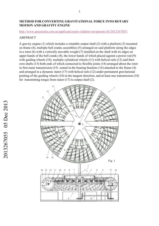
  • 1. 1 METHOD FOR CONVERTING GRAVITATIONAL FORCE INTO ROTARY MOTION AND GRAVITY ENGINE http://www.ipaustralia.com.au/applicant/zenin-vladimir-mr/patents/AU2013267055/ ABSTRACT A gravity engine (1) which includes a rotatable output shaft (2) with a platform (3) mounted on frame (4), multiple bell cranks assemblies (5) arranged on said platform along the edges in a rotor (6) with a vertically movable weight (7) installed on the shaft with its edges on upper hands of the bell cranks (8), the lower hands of which placed against a power rod (9) with guiding wheels (10), multiple cylindrical wheels (11) with helical rails (12) and their own shafts (13) both ends of which connected to flexible joints (14) arranged about the rotor in first main transmission (15) seated in the bearing brackets (16) attached to the frame (4) and arranged in a dynamic stator (17) with helical rails (12) under permanent gravitational pushing of the guiding wheels (10) in the tangent direction, and at least one transmission (18) for transmitting torque from stator (17) to output shaft (2). 201326705505Dec2013
  • 2. 2 TECHNICAL FIELD [0001] This invention relates to energy engineering and more particularly to the alternative energy technology of getting power from the force of gravity. [0001.1] In physics, a force is any interaction, which tends to change the motion of an object. In other words, a force can cause an object with mass to change its velocity (which includes to begin moving from a state of rest), i.e., to accelerate. Forces are also described as a push or pull on an object. They can be due to phenomena such as magnetism, gravity, wind or anything that might cause a mass to accelerate. Still more particularly this invention designed for converting gravity force into rotary motion. This conversion does not require the use of an additional external energy in accordance with the approval of the physics that any physical force alone can compel an object with mass to change its speed, which includes beginning to move from a state of rest. BACKGROUND [0002] Gravity as an energy source is hard to beat. It is free, it is in endless supply, and we do not have to import it, mine it, refine it, or grow it. It is powerful force that keeps us rooted to the ground and could end up powering our house someday. [0003] For centuries man has used weight-driven mechanical clocks that are powered by the gravitational pull of heavy weights slowly falling down. If the clock is equipped with a strike (gong, bell, rods, etc.), then a second or even third weight is used to rotate those mechanisms. [0004] Today a "Gravity Light", created by British designers Martin Riddiford and Jim Reeves, allows a cheap LED kit to run for up to thirty minutes for free through no more than a three-second pull on a cord. [0005] Unfortunately all weight driven mechanisms have the disadvantage that, depending on the construction and type of device, the weights must be wound or returned to their upper position by hand, daily or weekly. If one forgets the winding and the mechanism stops. [0006] A known solution to the problem is to increase the duration of the weight fall down by increasing the number of lines between the weight, or the pulley(s) attached to the weight, and the winding barrel, or the guide pulley(s) at the top of the weight channel. It is called 201326705505Dec2013
  • 3. 3 "fall compounding" and involves the use of extra pulleys. Wide experience shows that a system with more than three falls has excessive inherent friction losses, and that the decrease in vertical weight drop is not sufficient to justify the increased friction, heavier weight required, and the much longer weight line of a system with more than three falls. SUMMARY Technical Problem [0007] Weight-driven mechanisms stop working not because gravitational force terminates but because a cord wound on the winding drum of the main wheel unwinds over all its length. After stopping, the weight continues to press the bottom of the clock-case or floor with the same gravitational force as before but the mechanism cannot take this power because of the limitations of the known method and devices for converting gravitational force to rotary motion. Solution to Problem [0008] A radical solution would be to create a new method of converting gravitational force into rotary motion and a fundamentally different mechanism for carrying out this conversion, in which the heavy weight acting on this mechanism never changes its height position. Advantageous Effects of Invention [0009] It is the object of the present invention to provide a new method for converting gravitational force into rotary motion and a weight powered engine carrying out the steps of this method with no need to wind up a heavy weight. [0010] Proposed method for converting gravitational force to rotary motion comprises the following steps: a) using a heavy weight preferably in the form of a cylinder as a source of gravitational force and as the main component of a rotor; b) making the inlet in the centre of the weight with internal splines; c) making external splines formed longitudinally on the rotor's shaft that fit into corresponding internal splines in the weight inlet and rotatable installing shaft on a frame; 201326705505Dec2013
  • 4. 4 d) installing weight on said shaft's external splines for transmitting torque and providing the weight with the possibility of vertical sliding on the rotor's shaft; e) providing the decomposition of the weight's gravitational force into preferably equal component forces acting in a radial direction in a horizontal plane using guiding wheels; f) making a dynamic stator using multiple cylindrical wheels with the same diameter and providing helical rails similar to the threads of lead screw on these cylindrical wheels; g) providing every cylindrical wheel with its own shaft rotatable about its axis with one end connecting to the shaft's end of the next cylindrical wheel through the flexible joint; h) rolling up all cylindrical wheels and flexible joints about the weight thereby making a mane endless flexible transmission and all cylinders arranged into a ring around the rotor; i) putting all gravitational component forces through the guiding wheels on helical rails of said dynamic stator wheels in tangent direction; and j) providing at least one additional transmission for transmitting torque, rate and the rotation direction from the dynamic stator's cylindrical wheels to the rotor's shaft. [0011] An advantage of this method is that it enables the creation of gravity engines, which put into practice the abovementioned steps for converting gravitational force to rotary motion without the utilisation of long weight lines and a winding barrel. Disclosed gravity engine has no need for winding up a heavy weight. [0012] The gravity engine includes a frame, a rotor, a dynamic stator and a transmission for transmitting torque from the dynamic stator's revolving wheels to the rotor's shaft. [0013] An output rotor's shaft with round platform and one bevel gear is rotatable mounted on the engine frame. The rotor's shaft, said platform, and said gear serve as a basis for making the rotor. [0014] A heavy weight preferably in the form of a cylinder, that is a gravity force source, installed on the rotor's shaft over said platform. It has internal splines in the hole in its centre that fit with corresponding external splines on the rotor's shaft, which are installed upright. This provides the weight with the possibility of vertical sliding over said platform. [0015] Multiple bell crank assemblies are arranged along the edges of said platform. They provide the decomposition of the weight's gravitational force, acting downward, into preferably equal component forces, acting in a horizontal plane in a radial direction. 201326705505Dec2013
  • 5. 5 [0016] Every bell crank assembly is comprised of an "L" shaped crank which upper horizontal hand is under the heavy weight and lower vertical hand is placed against the power rod with a guiding wheel on its end. The power rod installed on a bell crank assembly base with the possibility of horizontal sliding in a radial direction. The guiding wheels finalize the structure of the rotor and are the major parts emitting gravitational component forces on the revolving parts of the dynamic stator's structure and providing force interaction between the rotor and the stator. [0017] A dynamic stator has multiple cylindrical wheels with the same diameter, each having its own shaft connected to the shaft of the next cylindrical wheel by means of a flexible joint with both ends seated in the bearing bracket fixed on the engine frame and arranged about the rotor in a main endless transmission. [0018] Every cylindrical wheel of the dynamic stator has helical rails affixed at an acute tangent angle upon the wheel. The helical rails finalize the structure of the dynamic stator. They are its major parts, taking the gravitational push of the rotor guiding wheels and providing force interaction between the dynamic stator revolving parts and the rotor. [0019] In this interaction multiple bell cranks of the rotor transmit the weight's gravitational force components to multiple power rods with guiding wheels on their ends, which permanently push all guiding rails of the dynamic stator wheels at an acute tangent angle. This action sets all dynamic stator wheels in the main endless transmission and the rotor with heavy weight in rotary motion at the same time. [0020] At least one additional transmission consists of a set of bevel gears for transmitting torque, rate and the rotation direction from the stator's guiding wheels to the rotor's shaft. This transmission provides the gravity engine with the synchronization and stabilization of the rotor's guiding wheels rolling along the dynamic stator's endless helical rails. [0021] The heavy weight gains motion in this gravity engine but it is a rotational motion in the horizontal plane with no change in its height position. [0022] As is well known a heavy revolving wheel in a machine is used to increase the machine's momentum and thereby provide greater stability. It is the so-called flywheel. In that way a heavy weight in this disclosed gravity engine is not just an energy source but a very useful flywheel too. 201326705505Dec2013
  • 6. 6 BRIEF DESCRIPTION OF DRAWINGS [0023] The invention will be better understood by reference to the accompanying drawings which illustrate the method and engine of the invention. Certainly, the present invention is not limited to the precise arrangement shown in the drawings, wherein: Fig. 1 is a top view and a side elevation in part section of the gravity engine constructed in accordance with the present invention. Fig. 2 is a perspective view of the gravity engine illustrated in Fig. 1. Fig. 3 is a perspective view of the gravity engine with all dynamic stator's wheels removed. This provides a good overview of the remaining components of the design. Fig. 4 is a perspective side view of the gravity engine with all rotor components removed with the exception of the output shaft. This provides a good overview of the remaining components of the design. Fig. 5 is an enlarged perspective side view on the main components of the engine in Fig. 1 in part section illustrating in detail how the torque from the dinamic stator's wheels is transmited to the rotor shaft. A vector diagram illustrates the tangential component of force action and curved arrows show the rotation directions of all revolving components and explain the principle of the engine operation. Fig. 6 is 48 cylindrical wheels of the dynamic stator (referring to Fig. 1, Fig 2 and Fig. 4), assembled in one long cylinder with one long shaft. This illustrates that the gravitational force corresponding to the heavy weight acts on all the wheels of the dynamic stator in tangential direction simultaneously, resulting in their clockwise rotation, and helical rails, in response, force guiding wheels of the rotor to move along the cylinders. Fig. 7 is 48 cylindrical wheels of the dynamic stator, assembled in one long cylinder with diameter D, length L and twelve start helical rails, similar to leadscrew threads with lead l and pitch p, which is used to translate the turning motion of this cylinder into the linear motion of the guiding wheels, rolling along the rails; Fig. 8 is the cylinder shown in Fig. 6 rolled up in a ring in the supposition that the long cylinder and its helical rails are continuous and flexible (it is a hypothetical flexible ring with all continuous and endless helical rails). 201326705505Dec2013
  • 7. 7 Fig. 9 is the cylinder shown in Fig. 6 cut into 48 sections and rolled up in a real ring, disposing all sections closely just inside of the ring, as it is shown in Fig. 1, Fig. 2 and Fig. 4 where inside the ring all helical rails are continuous and form continuous twelve endless tracks during rotation. Fig. 10 is an enlarged perspective view of two dynamic rotor wheels in part section. The shaft of each wheel connects with shafts of two nearby wheels through universal joints with both ends seated in the bearing bracket fixed on the engine frame. This picture also shows two bevel gears providing rotary motion transmision from the endless flexible shaft (main transmission) to the rotor's shaft. Fig. 11 is an enlarged view of the bell-crank assemblies where a bell-crank is a rectangular lever by which the direction of force action changes through an angle of 90 degrees, and by which its mechanical advantage alters by making the hands of different lengths. Fig. 12 is an enlarged perspective view of two dynamic rotor wheels with the overlapping helical rails providing the guiding wheels with smooth uninterrupted rolling along the continuous endless tracks with the smallest possible tangential angle. Fig. 13 is a kinematic scheme of a gravity engine with a triple transmission of torque from the dynamic stator to rotor's shaft. DESCRIPTION OF EMBODIMENTS [0024] In accordance with the generally accepted definition of the “engine”, it converts energy into mechanical force or motion. It is incorrect definition. Energy cannot set in motion a complex machinery. It must first be converted into a physical force. Physical force and only physical force can set in motion all the moving parts of any engine. [0025] The force of compressed steam drives a steam engine, and the force of the gas explosion in cylinders drives our car. Clockwork motors in wind-up clocks and toys operate under the influence of elastic/spring force. Weight-driven clocks operate by weights that, under gravity, drive the hands of the clock in their rotational movement by means of a gear train. Pneumatic motors use the force of a compressed air. A windmill operate using the wind force to make energy. A waterwheel uses force of linear motion of river water and convert it into rotational motion and so on. 201326705505Dec2013
  • 8. 8 [0026] The disclosed engine uses gravity, one of the fundamental forces of nature. Unfortunately, we know very little about the physical nature of this power, but it could not stop us using it successfully. [0027] The main elements of the design in the disclosed engine, carrying out the conversion of a physical force in rotational motion are the rotor with multiple bell crank assemblies, dynamic stator, made in the form of a torus with endless helical rails on its surface, and transmission for transmitting torque from the dynamic stator to the rotor's shaft. Toroidal mechanical construction never before used in engineering though has unique properties. The uniqueness lies in the fact that in the synchronous rotation of the cylinders, forming torus, rails on their surfaces create continuous endless railways on the inner surface of the torus, where the rotor guiding wheels roll under the influence of the physical force endlessly to breakage or complete wear of the engine components. [0028] Referring first to the drawings in Figs. 1 and Fig. 2, the numeral 1 designates the invented gravity engine. [0029] Due to the high density of the engine components in Fig. 1 and Fig. 2, some of them remain closed for viewing. To get out of a difficult situation some components of the gravity engine 1 shown in Fig. 3 and Fig. 4 are taken away. Therefore, in Fig. 3, all dynamic stator's wheels are lacking and in Fig. 4, all rotor components are lacking with the exception of the rotor's shaft. This provides a good overview of the remaining components of the design on both drawings. [0030] As depicted in Figs. 1 - 4 the gravity engine 1 includes frame 4, rotor 6, dynamic stator 17 and at least one transmission 18 for transmitting torque, rate and the rotation direction from the dynamic stator's wheels 11 to rotor's shaft 2. [0031] These drawings illustrate frame 4 in the form of transparent cage so that all engine parts are visible. It is the gravity engine housing. No thermal process occurs inside the gravity engine housing except friction in bearings (the shafts of all rotating components have the bearings). Therefore, frame 4 can be solid. [0032] Rotor 6 includes a substantially disk-shaped platform 3, affixed to the shaft 2, rotatable mounted on the engine frame 4. A heavy weight 7 mounted on said shaft 2, and multiple bell crank assemblies 5 arranged on said platform along the edges. 201326705505Dec2013
  • 9. 9 [0033] The heavy weight 7, which is a gravity force source, has internal splines in the hole in its centre that fit with corresponding external splines on the rotor's output shaft 2 providing the weight with the possibility of vertical sliding over the platform 3. [0034] Referring to Fig. 5 and Fig. 11, every bell-crank assembly 5 comprises of an "L" shaped crank 8 which has an upper horizontal hand with its end under the heavy weight 7 and lower vertical hand, placed against power rod 9 installed on the bell crank assembly base with the possibility of sliding in a radial direction. Every power rod 9 has guiding wheel 10 on its end. [0034.1] In this case, bell-cranks 8 are only used for transmitting the input force through a right angle and its amplification, if necessary, but not for transmitting a motion. Bell crank 8, power rod 9 and guiding wheel 10 are in the same position in bell-crank assemblies 5 during engine operation. The guiding wheels 10 is constantly stay on helical rails 12 of the dynamic stator, power rod 9 is in constant contact with the lower hand of the bell cranks 8 and the guiding wheels 10 and the upper hand of the bell-cranks 8 is in constant contact with the weight 7. All of these mechanical elements 8, 9 and 10 transmit the force F to the wheels of the dynamic stator at an acute tangent angle and do not participate in the movement as the distance from the rotor axis to the helical rails 12 on the surface of the dynamic stator’s wheels all the time remains constant. Thus, the platform 3 of the rotor undergoes no pushing from force F, and the whole of its power is applied only to the wheels 11 of the dynamic stator at an acute tangent angle. Wheels of the dynamic stator can not remain dormant under the influence of this force. They begin rotational motion and involve in motion weight 7 and all the moving parts of the engine. [0035] All objects upon earth experience a force of gravity that is directed downward towards the centre of the earth. The force of gravity on earth is always equal to the weight of the object as found by the equation: F = m g , where g is a gravitational acceleration, g = 9.8 metres/second 2 and m - mass (in kg). [0036] Bell crank assemblies 5 provide the decomposition of the weight's 7 gravitational force F into equal component forces F/n, acting in radial direction through guiding wheels 201326705505Dec2013
  • 10. 10 10 in a horizontal plane, where n is a number of bell crank assemblies in rotor (n = 24). The dynamic stator has n/2 of the helical rails (in this case n/2 = 12). [0037] Guiding wheels 10 finalize the structure of the rotor 6 and are its major parts emitting gravitational force F on the rotating parts of the dynamic stator and providing force interaction between the rotor and the stator. [0038] The dynamic stator 17 includes multiple cylindrical wheels 11 with their own shafts 13 rotatable about their axes with both ends connected to the shaft's ends of the nearby stator wheels through flexible joints 14 with both ends seated in the bearing bracket 16 fixed on the engine frame 4. [0039] This makes all dynamic stator wheels 11arranged on the main endless transmission 15 in a circle about the rotor 6. [0040] Guiding helical rails 12 are affixed at an acute tangent angle upon the dynamic stator cylindrical wheels 11. [0041] As depicted in Figs. 5 and 6 all helical rails are under the double permanent gravitational push of the guiding wheels 10 with force F/n . Inasmuch as the dynamic stator cylinders have two times less the number of helical rails as the rotor has guiding wheels (in this case n/2 = 12 ), the entire gravitational force F/n × 2×n/2 = F will push all dynamic stator cylindrical wheels in a tangent direction simultaneously. [0042] This means that all the dynamic stator's wheels are under the permanent pushing of the gravitational force F at an acute tangent angle θ. [0043] There are two components of force in circular motion: tangential Ft and normal Fr . The tangential component Ft acts along the tangent while the normal component acts along the radius r. Only the tangential component Ft of the force F generates torque. The radial component Fr will not affect the torque about point p. [0044] Torque is a measure of how much a force F acting on a wheel causes that wheel to rotate. The wheel rotates about an axis, which is the pivot point p. The distance from the pivot point to the point, where the force acts is the moment arm, and denoted by r. Note that this distance r is also a vector, and points from the axis of rotation to the point where the 201326705505Dec2013
  • 11. 11 force acts. Refer to Fig. 6 for a clear representation of these definitions. Torque (or a rotational force) τ is defined as τ = r ×F = r F sin θ. [0045] Evidently, the less the angle θ the greater the rotational force. [0046] The drawings in Fig. 6, Fig. 7, Fig. 8 and Fig. 9 explain how the gravity engine works. [0047] Referring to Fig. 6, the cylindrical wheels 11 of the dynamic stator are assembled in one long cylinder with one long shaft. This is done to illustrate that the gravitational force F corresponding to the heavy weight 7 acts upon all the cylindrical wheels of the dynamic stator in a tangential direction simultaneously. This results in their clockwise rotation. In response to this action the helical rails force the guiding wheels 10 of the rotor to roll along the dynamic stator cylinders 11. In that case, a long cylinder with helical rails 12 acts as a mechanical linear actuator that converts these rails' 12 rotational motion to the linear motion of the guiding wheels 10. [0048] In Fig. 7 the 48 cylindrical wheels of the dynamic stator are assembled in one long cylinder with diameter D, length L and twelve start helical rails, similar to a leadscrew threads with lead l and pitch p. The helical rails just as the leadscrew threads are used to translate the turning motion of this cylinder into the linear motion of the guiding wheels 10 rolling along the rails 12. [0049] A lead l is the axial advance of the helical rails during one complete turn (360°) and pitch p is defined as the axial distance between adjacent helical rails 12 and thus the distance between adjacent guiding wheels 10. [0050] Moreover the lead l is the axial travel of the rotor guiding wheels for a single revolution of the cylinder in Fig. 7. In this case during the two revolutions of the dynamic stator's wheels every rotor's guiding wheel goes all the way L = 2l. [0051] This means that in gravity engine 1 during the two revolutions of the dynamic stator wheels only one revolution of the rotor takes place. That is why the bevel gears 20 and 19 of the transmission 18 shown in Fig. 5 and Fig. 10 have ratio 2 : 1 (24 teeth and 12 teeth). 201326705505Dec2013
  • 12. 12 [0052] If a total length L of all dynamic stator's wheels is equal to L, 3L, 4L and so on, we have to use gears ratio 1 : 1, 3 : 1, 4 : 1 and so on accordingly. [0053] In Fig. 8, the cylinder shown in FIG. 6 rolled up in a ring in the supposition that the long cylinder and its helical rails are continuous and flexible (it is a hypothetical flexible ring with all continuous and endless helical rails). [0054] However, it is quite possible to get a real functioning cylindrical ring with endless rails in a special place of the ring. Here is an example: referring to Fig. 9 the cylinder shown in Fig. 6 and Fig. 7 has been cut into 48 equal sections and rolled up in real composite ring disposing all sections (dynamic stator's wheels 12) closely just inside of the ring. As it is shown in Fig. 1, Fig. 2 and Fig. 4, all helical rails inside of the ring are continuous and form continuous endless tracks during rotating. [0055] Fig. 10 shows an enlarged view of two dynamic stator cylindrical wheels 11 which have their shafts connected to the shafts of two nearby wheels through universal joints 14 with both ends seated in the bearing bracket 16 fixed on the engine frame 4. This picture also shows two bevel gears providing rotary motion transmision from the main endless flexible shaft 15 to the output shaft 2 in accordance with their ratio (driver 12 teeth, driven 24 teeth): 𝐷𝑟𝑖𝑣𝑒𝑛 𝐷𝑟𝑖𝑣𝑖𝑛𝑔 = 24 12 = 2 1 = 2 : 1 It means for every two rotations of the driving gear, the driven gear makes one rotation. As a result for every two rotations of dinamic stator's wheels, the rotor makes one rotation because the rest of the gears in transmission 18 and gear 26 have ratio 1 : 1. [0056] Fig. 11 shows an enlarged view of the bell-crank assemblies 5 where a bell-crank 8 is a rectangular lever by which the direction of motion is changed through an angle of 90 degrees, and by which its mechanical advantage may be altered by differing the length of the hands. [0057] This means that the longer upper horizontal hands of the bell cranks are the less weight we can use for getting the same energy. [0058] Fig. 12 illustrates an enlarged perspective view of the wheels 11with the helical rails 12 overlapping 27. This is one example of the helical rails construction providing 201326705505Dec2013
  • 13. 13 uninterrupted endless tracks 12 for guiding wheels 10 with the smallest possible tangential angle θ. [0059] Fig. 13 shows a kinematic scheme of the gravity engine with a triple transmission of torque from the dynamic stator's main endless transmission 15 to the rotor's shaft 2. [0060] Every transmission 18 consists of a driving bevel gear 19, a driven bevel gear 20 with shaft 21, a bevel gear 22 attached to this shaft, a bevel gear 23 with shaft 24 and a bevel gear 25 attached to this shaft. Three bevel gears 25 are the driving gears with respect to bevel gear 26. Driven gear 26 is attached to rotor's shaft and sets rotor in motion by means of three transmissions 18 at the same time. [0061] The described gravity engine has a long main flexible transmission with 48 universal joints in series. The triple transmission of torque from dynamic stator to the rotor's shaft provides three equal parts of the main long transmission with unloading. [0062] A present-day technology of the flexible shafts for power transmission, which is used to transmit rotary power along a curved path, covers most applications in machines now and it is possible to use them in the gravity engine instead of the multiple universal joints and bevel gears someday. [0062.1] Newton’s second law reads as follows: The acceleration a of an object as produced by a net force Fn is directly proportional to the magnitude of the net force, in the same direction as the net force, and inversely proportional to the mass m of the object: Fn = ma. In this engine, the net force is the gravitational force of heavy weight 7. Under an assumption of constant gravity near the surface of the Earth, Newton's law of universal gravitation simplifies to definition of the gravitational force as Fg = mg, where m is the mass of the weight 7 and g is a constant vector with an average magnitude of 9.81 m/s2 . The acceleration of the engine that produced by this force is directly proportional to the magnitude of this force, and inversely proportional to the mass m∑ of all moving components of this engine. They do not move in direction of this force action because multiple bell crank assemblies 5 transmit this force to helical rails 12, and whole of the force Fg power pushes wheels 11 of the dynamic stator in tangent direction at an acute tangent angle. This leads to the rotational movement of the rotor and all dynamic stator’s cylindrical wheels with acceleration. 201326705505Dec2013
  • 14. 14 Industrial Applicability [0063] The disclosed gravity engine does not contravene the laws of physics and its performance specification is not beyond calculations and engineering design. No special design techniques or unique technologies are needed to build this engine. It can be built using common components and materials of modern machines and mechanisms. [0064] Harnessing energy from gravitational pull would be of great advantage. Gravitational pull is relatively constant at all times and in all conditions. This would allow energy generation systems to be virtually universal without regard for terrain, weather, or other uncontrollable events such as those related to geography and political systems. What is very important is that the energy source is clear. CLAIMS 1. A method for converting gravitational force into a rotary motion comprising of the following steps: a) using a heavy weight preferably in the form of a cylinder as a source of gravitational force and as the main component of a rotor; b) making an inlet in the centre of the weight with internal splines; c) making external splines formed longitudinally on a rotor's shaft that fit into corresponding internal splines in the weight inlet; d) installing weight on said shaft's external splines for transmitting torque and providing the weight with a possibility of vertical sliding on the rotor's shaft; e) providing the decomposition of the weight gravitational force into preferably equal component forces acting in a radial direction in a horizontal plane using guiding wheels; f) making a dynamic stator using multiple cylindrical wheels with the same diameter and providing helical rails similar to lead screw's threads on these cylindrical wheels; g) providing every cylindrical wheel with its own shaft rotatable about its axis with one end connecting to shaft's end of the next cylindrical wheel through a flexible joint; 201326705505Dec2013
  • 15. 15 h) rolling up all the cylindrical wheels' shafts and flexible joints into a circle around the weight thereby making a mane endless flexible transmission and all cylinders arranged in a ring around the rotor; i) putting all gravitational component forces through the guiding wheels on the helical rails of said dynamic stator wheels in tangent direction; and j) providing at least one additional transmission for transmitting torque, rate and the rotation direction from the dynamic stator cylindrical wheels to the rotor's shaft. 2. A gravity engine comprising: a) a frame; b) a rotatable output shaft with external splines, a round platform and a gear, mounted on said frame; c) multiple bell crank assemblies arranged along the edges of said platform; d) a heavy weight preferably in the form of a cylinder with internal splines in the hole in its centre installed on said output shaft's corresponding external splines with a possibility of vertical sliding over said platform; e) multiple cylindrical wheels with the same diameter, each having its own shaft connected to the shaft of the next cylindrical wheel by means of a flexible joint with both ends seated in the bearing bracket fixed on the engine frame and arranged about the rotor in a dynamic stator with a main endless transmission; and f) at least one additional transmission with a set of gears for transmitting torque, rate and the rotation direction from the dynamic stator's wheels to the output rotor's shaft. 3. The gravity engine of claim 2, wherein every bell crank assembly comprises of an "L" shaped crank having an upper horizontal hand with its end under the heavy weight and lower vertical hand that placed against the power rod installed on the bell crank assembly base with the possibility of sliding in radial direction and having on its end a guiding wheel. 4. The gravity engine of claim 3, wherein every cylindrical wheel of the dynamic stator has helical rails affixed at an acute tangent angle upon the wheel. 5. The gravity engine of claim 4, wherein all helical rails on dynamic stator wheels are overlapping. 201326705505Dec2013
  • 16. 16 6. The gravity engine of claim 5, wherein helical rails on dynamic stator wheels are under permanent gravitational push of the rotor's guiding wheels in an acute tangent angle. 7. The gravity engine of claim 6, wherein the additional transmission consists of a set of gears transmitting torque, rate, and the rotation direction from the stator's guiding wheels to the rotor's shaft. DRAWINGS 201326705505Dec2013
  • 17. 17 Gravity Engine animation https://makeagif.com/i/MZvaq8 Gravity Engine animation https://makeagif.com/i/X4ZQuP 201326705505Dec2013
  • 22. 22 Gravity Engine animation https://makeagif.com/i/MZvaq8 Gravity Engine animation https://makeagif.com/i/X4ZQuP 201326705505Dec2013