More Related Content
More from Trigonenterprisespvtltd
More from Trigonenterprisespvtltd (18)
Ahub face mill cutter.
- 2. Indexable Milling Tools
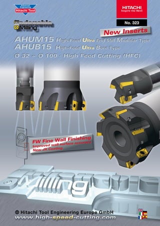
AHU15 | High Feed Ultra
HIGH-FEED ULTRA END MILL
HIGH-FEED ULTRA END MILL
1. Main cutting forces are reduced by the unique high rake
geometry
1. El esfuerzo de corte se reduce gracias a una exclusiva
geometría altamente positiva.
2. Ramp milling is possible
2. Capaz de mecanizar en rampa
3. 30% increased rigidity over conventional indexable endmills due to the utilization of a special steel material and
chip pocket geometry
3. 30% más de rigidez que herramientas de plaquita
4. Through tool coolant is available
5. Dispone de canal de refrigeración interior.
5. New substrate and coating technology has been adopted
which allows longer tool-life and the ability to use higher
cutting speeds
HIGH-FEED ULTRA END MILL
4. convencionales gracias a la utilización de un acero especial y a la geometría del canal de evacuación de viruta
6. La combinación de substratos y recubrimientos de ultima
tecnología permite una mayor vida de herramienta y la
capacidad de usar velocidades de corte mayores
HIGH-FEED ULTRA END MILL
1. Durch die einzigartige hochpositive Schneidengeometrie
des AHU High Feed Ultra wird der Schnittdruck erheblich
reduziert
1. L’angle de dépouille très prononcé permet à lui seul de
réduire la majeure partie des efforts de coupe.
2. Auch Fräsoperationen über Rampe sind möglich
3. Rigidité accrue de 30% par rapport aux fraises à plaquettes rapportées due à l’utilisation d’un acier spécial et à la
forme des poches à copeaux.
3. Die Verwendung eines speziellen Stahls und einer neu
entwickelten Spankammer-Geometrie erhöhte die Steifigkeit des AHU High Feed Ultra gegenüber konventionellen
WSP-Haltern um 30%
4. Zusätzlich verfügt der AHU High Feed Ultra über innen
liegende Kühlkanäle
5. Durch das neue Substrat der Wendeschneidplatten in
Verbindung mit einer neuen Beschichtungstechnologie
ermöglicht der AHU High Feed Ultra wesentlich höhere
Schnittgeschwindigkeiten bei gleichzeitig längeren
Standzeiten
2. L’usinage de rampes est possible (ramping).
4. Deux versions de corps sont disponibles : avec ou sans
arrosage au centre.
5. Nous avons développés une nouvelle nuance et une nouvelle technologie de revêtement générant une durée de vie
supérieure et une augmentation significative des vitesses
de coupe.
HIGH-FEED ULTRA END MILL
1. Maggiore stabilità e minori forze di taglio grazie alla nuova
geometria positiva della spoglia.
2. La fresatura in rampa è possibile
3. 30 % maggiore rigidità a confronto con frese convenzionali grazie alla particolare geometria del collo rompitruciolo e una microfusione di acciaio del corpo fresa.
4. Refrigerante attraverso il corpo fresa disponibile
5. La combinazione dello sviluppo di una micrograna
6. particolare con l´ultimo sviluppo di rivestimenti rende
possibile un grande allungamento di vita dell’utensile e
l´utilizzo di velocità di taglio più elevate.
2
© 2009 Hitachi Tool Engineering Europe GmbH
Errors and alterations excepted · Änderungen und Irrtum vorbehalten
- 3. Indexable Milling Tools
AHUM15 | High Feed Ultra Modular Type
Q max
Jet
High Efficient
Air Hole
No. of
Teeth
HRC
Roughing
Finishing
50
3~4
M
l
H
Ød1 Ød2
ØD
H
M
C
E
A
Ød2
Ød1
ØD
B
H
l
A
Tolerance
Torque on screw
B
Modular Type
ID Code Item Code
AHUM-1532R-3-M16
FH066
AHUM-1540R-4-M16
FH067
Flutes
3
4
ØD
32
40
H
40
45
ØD 0/-0.2
3 Nm
Ød1
M
Ød2
A
B
C
E
l
17
16
28.8
6
23
12
22
14
Inserts
JDMT1505..R.. JX10..
AHUB15 | High Feed Ultra Bore Type
Q max
Jet
High Efficient
Air Hole
No. of
Teeth
HRC
Roughing
Finishing
50
4~8
Ød2
Ød
A
B
C
Ød2
Ød
H
A
H
B
l
M
C
E
C
H
Ød2
Ød1
ØD
ØD
l
A
Ød1
B
ØD
Tolerance
Torque on screw
Face Mill
ID Code
FH060
FH061
FH062
FH063
FH064
FH065
Item Code
Flutes ØD
AHUB-1540RM-4-16
40
4
AHUB-1550RM-5-22
50
5
AHUB-1550RM-5-27
AHUB-1563RM-6-27
63
6
AHUB-1580RM-7-27
80
7
AHUB-15100RM-8-32
100
8
H
45
50
63
Ød
16
22
Ød1
11.5
17
M
8*
10
27
20
12
32
26
16
Ød2
35
40
45
60
70
A
8.4
10.4
B
5.6
6.3
C
18
20
12.4
7
22
14.4
8
ØD 0/-0.2
3 Nm
I
25.5
14
Inserts
JDMT1505..R.. JX10..
* Special Screw
© 2009 Hitachi Tool Engineering Europe GmbH
Errors and alterations excepted · Änderungen und Irrtum vorbehalten
3
- 4. Indexable Milling Tools
A
INSERTS
B
15°
A
R
B
T
15°
T
R
ID Code
WF182
WF183
WF184
WF185
WF186
WF187
Item Code
JDMT150504R-FW JX1045
JDMT150508R-FW JX1020
JDMT150508R-FW JX1045
JDMT150508R-FW JX1060
JDMT150520R JX1045
JDMT150530R JX1045
NEW
P01
P10
P20
P30
P40
Grade
JX1045
JX1020
JX1045
JX1060
JX1045
JX1045
A
9.12
5
M01
Grade Overview
ISO
M10
M20
M30
M40
K01
K10
K20
JX1060
N40
S10
S20
K40
JX1045
JX1060
S01
K30
JX1020
JX1045
N30
0.8
JX1020 – 1060 PVD Coating / Dry Cutting
JX1020
N20
R
0.4
2.0
3.0
JX1045
N10
T
16
JX1020
N01
B
S30
JX1060
S40
H01
H10
JX1020
H20
H30
H40
JX1020
JX1060
Parts
Clamp Screw
Wrench
ID-Code
Item-Code
ID-Code
Item-Code
ET038
412-141
ET049
105-T15
AHU-M
AHU-B
Special screw
AHUB-1540RM-4-16
4
ID-Code
Item-Code
ET050
K06-676
© 2009 Hitachi Tool Engineering Europe GmbH
Errors and alterations excepted · Änderungen und Irrtum vorbehalten
- 5. Indexable Milling Tools
AHU15 | High Feed Ultra – improved cutting surface
Fine Wall type JDMT……R-FW
Fine Wall type JDMT……R-FW
Conventional (JDMT……R)
Conventional (JDMT……R)
= outermost point
= outermost point
= outermost point
= outermost point
aeae
aeae
(mm)
apap (mm)
(mm)
apap (mm)
Ramp Angle
Ramping
Hole Ø
Helical Milling
Cutting edge Ø (mm)
Ramping Angle
Helical Milling / Hole Dia. (mm)
Ø 32
4°
47~60
40
3°
64~76
50
2°
83~96
63
1.5°
122~109
80
1°
156~143
100
1°
196~183
AHU15 | Recommended Cutting Conditions
1. Please choose the best conditions from the table
2. To reduce tool breakage index the inserts earlier than the maximum edge life
3. Chips can become hot and can cause burns or damage to eyes. Please ensure
machine guards are used, and safety specs and gloves worn at all times when
carrying out work near to the tool or workpiece
4. Please ensure caution when using neat cutting oil due to the risk of fire
1. Bitte wählen Sie aus der Tabelle die für Ihre Anwendung am besten geeigneten
Bedingungen
2. Um die Gefahr des Werkzeugbruchs zu reduzieren, sollten die
Wendeschneidplatten gewechselt werden, bevor die maximale Standzeit der
Schneide erreicht ist
3. Die während der Bearbeitung entstehenden Späne können sehr heiß werden
und zu Verbrennungen oder Verletzungen von Haut und Augen führen.
Bitte stellen Sie sicher, dass während der Bearbeitung die Maschinentüren
geschlossen sind. Bei Arbeiten in der Nähe oder direkt am Werkzeug oder
Werkstück, sollten immer eine Schutzbrille und Handschuhe getragen werden
4. Erhöhte Vorsicht ist geboten beim Einsatz von purem Schneidöl,
da es sich während der Bearbeitung entzünden kann
1. Seleccionar las condiciones de la tabla de indicada
2. Para reducir el riesgo de rotura de la herramienta hay cambiar la plaquita antes
de agotar la vida máxima del filo
3. Las virutas pueden saltar candentes y pueden causar quemaduras o daño en
los ojos.
4. Por favor, asegúrese de cerrar las protecciones de la máquina y de que son
utilizados gafas y guantes en todo momento al realizar trabajos cerca de la
herramienta o la pieza.
5. Por favor, tome precaución al utilizar aceite de corte debido al riesgo de
ignición.
1. Veuillez choisir les conditions de coupes les mieux adaptées grâce au tableau.
2. Pour réduire les risques de rupture de l’outil, changez l’insert avant d’avoir
atteint la durée de vie maximale de l’arrête de coupe.
3. Les copeaux peuvent devenir chauds et causer des lésions oculaires ou
des brûlures. Veuillez vous assurer que les protections de la machines sont
correctement utilisées, et que des lunettes et des gants soient portés pour tout
travail à proximité de l’outil ou de la pièce à usiner.
4. Prenez vos précautions lors d’utilisation d’huiles de coupes à cause des risques
d’incendie
1. Scegliere le condizioni migliori della tabella indicata.
2. Per evitare la rottura dell’utensile cambiate l´inserto prima di arrivare all’usura
massima.
3. I trucioli possono essere molto caldi durante il lavoro. Usate sempre i mezzi
di sicurezza (Occhiali, guanti, vetri di sicurezza…) durante il lavoro vicino
all’utensile o al materiale.
4. Attenzione al rischio di fiamma se durante il lavoro usate refrigerante a base di
olio.
AHU15 | Adjust of Cutting Conditions for Finishing
For finishing please adjust the cutting conditions as follows:
Vc
fz
0.1 mm
ap
~ 5 mm maximum
ae
Finishing
+50 %
0.3 ~ 0.5 mm
© 2009 Hitachi Tool Engineering Europe GmbH
Errors and alterations excepted · Änderungen und Irrtum vorbehalten
5
- 6. AHU15 | Recommended Cutting Conditions
ØD 32 / Z3 / modular type
Side
I
Mild steel
(<200HB)
II
Carbon steel; Alloy
JX1045
steel (<30HRC)
III
Carbon steel; Alloy JX1045
steel (30-40HRC) JX1020
IV
Pre-hardened
steel; Tool Steel
(40-50HRC)
JX1020
Stainless steel
(dry condition)
JX1045
Stainless steel
(wet condition)
JX1060
VIII
Cast Iron; GG;
GGG
JX1045
JX1020
*
Titanium Alloy
(wet condition)
JX1060
*
Aluminium Alloy
(wet condition)
JX1020
JX1045
VI
Vc (m/min)
n (min-1)
fz (mm/tooth)
Vf (mm/min)
ap (mm) max.
ae (mm) max.
cm3
Vc (m/min)
n (min-1)
fz (mm/tooth)
Vf (mm/min)
ap (mm) max.
ae (mm) max.
cm3
Vc (m/min)
n (min-1)
fz (mm/tooth)
Vf (mm/min)
ap (mm) max.
ae (mm) max.
cm3
Vc (m/min)
n (min-1)
fz (mm/tooth)
Vf (mm/min)
ap (mm) max.
ae (mm) max.
cm3
Vc (m/min)
n (min-1)
fz (mm/tooth)
Vf (mm/min)
ap (mm) max.
ae (mm) max.
max. cm3
Vc (m/min)
n (min-1)
fz (mm/tooth)
Vf (mm/min)
ap (mm) max.
ae (mm) max.
cm3
Vc (m/min)
n (min-1)
fz (mm/tooth)
Vf (mm/min)
ap (mm) max.
ae (mm) max.
cm3
Vc (m/min)
n (min-1)
fz (mm/tooth)
Vf (mm/min)
ap (mm) max.
ae (mm) max.
cm3
Vc (m/min)
n (min-1)
fz (mm/tooth)
Vf (mm/min)
ap (mm) max.
ae (mm) max.
cm3
220
2,189
0.25
1,642
10
9.6
158
220
2,189
0.25
1,642
8.5
9.6
134
154
1,533
0.2
920
7
9.6
62
110
1,095
0.15
493
5
9.6
24
330
3,284
0.25
2,463
8
9.6
189
154
1,533
0.25
1,149
8
9.6
88
220
2,189
0.25
1,642
10
9.6
158
66
657
0.2
394
10
9.6
38
660
6,568
0.25
4,926
10
9.6
473
Slotting
154
1,533
0.175
805
5
32
129
154
1,533
0.175
805
4.25
32
109
108
1,073
0.14
451
3.5
32
50
77
766
0.105
241
2.5
32
19
231
2,299
0.175
1,207
4
32
154
108
1,073
0.175
563
4
32
72
154
1,533
0.175
805
5
32
129
46
460
0.14
193
5
32
31
462
4,598
0.175
2,414
5
32
386
ØD 40/ Z4 / modular type
Side
Slotting
220
1,752
0.25
1,752
10
12
210
220
1,752
0.25
1,752
8.5
12
179
154
1,226
0.2
981
7
12
82
110
876
0.15
525
5
12
32
330
2,627
0.25
2,627
8
12
252
154
1,226
0.25
1,226
8
12
118
220
1,752
0.25
1,752
10
12
210
66
525
0.2
420
10
12
50
660
5,255
0.25
5,255
10
12
631
154
1,226
0.175
858
5
40
172
154
1,226
0.175
858
4.25
40
146
108
858
0.14
481
3.5
40
67
77
613
0.105
257
2.5
40
26
231
1,839
0.175
1,287
4
40
206
108
858
0.175
601
4
40
96
154
1,226
0.175
858
5
40
172
46
368
0.14
206
5
40
41
462
3,678
0.175
2,575
5
40
515
ØD 50 / Z5 / bore type
Side
220
1,401
0.25
1,752
10
15
263
220
1,401
0.25
1,752
8.5
15
223
154
981
0.2
981
7
15
103
110
701
0.15
525
5
15
39
330
2,102
0.25
2,627
8
15
315
154
981
0.25
1,226
8
15
147
220
1,401
0.25
1,752
10
15
263
66
420
0.2
420
10
15
63
660
4,204
0.25
5,255
10
15
788
Slotting
154
981
0.175
858
5
50
215
154
981
0.175
858
4.25
50
182
108
687
0.14
481
3.5
50
84
77
490
0.105
257
2.5
50
32
231
1,471
0.175
1,287
4
50
257
108
687
0.175
601
4
50
120
154
981
0.175
858
5
50
215
46
294
0.14
206
5
50
51
462
2,943
0.175
2,575
5
50
644
* Possible, please pay attention for reduced tool life.
6
© 2009 Hitachi Tool Engineering Europe GmbH
Errors and alterations excepted · Änderungen und Irrtum vorbehalten
- 7. AHU15 | Recommended Cutting Conditions
ØD 63 / Z6 / bore type
Side
I
Mild steel
(<200HB)
II
Carbon steel; Alloy
JX1045
steel (<30HRC)
III
Carbon steel; Alloy JX1045
steel (30-40HRC) JX1020
IV
Pre-hardened
steel; Tool Steel
(40-50HRC)
JX1045
JX1020
Stainless steel (dry
JX1045
condition)
VI
Stainless steel
(wet condition)
JX1060
VIII
Cast Iron; GG;
GGG
JX1045
JX1020
*
Titanium Alloy
(wet condition)
JX1060
*
Aluminium Alloy
(wet condition)
JX1020
Vc (m/min)
n (min-1)
fz (mm/tooth)
Vf (mm/min)
ap (mm) max.
ae (mm) max.
cm3
Vc (m/min)
n (min-1)
fz (mm/tooth)
Vf (mm/min)
ap (mm) max.
ae (mm) max.
cm3
Vc (m/min)
n (min-1)
fz (mm/tooth)
Vf (mm/min)
ap (mm) max.
ae (mm) max.
cm3
Vc (m/min)
n (min-1)
fz (mm/tooth)
Vf (mm/min)
ap (mm) max.
ae (mm) max.
cm3
Vc (m/min)
n (min-1)
fz (mm/tooth)
Vf (mm/min)
ap (mm) max.
ae (mm) max.
max. cm3
Vc (m/min)
n (min-1)
fz (mm/tooth)
Vf (mm/min)
ap (mm) max.
ae (mm) max.
cm3
Vc (m/min)
n (min-1)
fz (mm/tooth)
Vf (mm/min)
ap (mm) max.
ae (mm) max.
cm3
Vc (m/min)
n (min-1)
fz (mm/tooth)
Vf (mm/min)
ap (mm) max.
ae (mm) max.
cm3
Vc (m/min)
n (min-1)
fz (mm/tooth)
Vf (mm/min)
ap (mm) max.
ae (mm) max.
cm3
220
1,112
0.25
1,668
10
18.9
315
220
1,112
0.25
1,668
8.5
18.9
268
154
778
0.2
934
7
18.9
124
110
556
0.15
500
5
18.9
47
330
1,668
0.25
2,502
8
18.9
378
154
778
0.25
1,168
8
18.9
177
220
1,112
0.25
1,668
10
18.9
315
66
334
0.2
400
10
18.9
76
660
3,336
0.25
5,005
10
18.9
946
Slotting
154
778
0.175
817
5
63
257
154
778
0.175
817
4.25
63
219
108
545
0.14
458
3.5
63
101
77
389
0.105
245
2.5
63
39
231
1,168
0.175
1,226
4
63
309
108
545
0.175
572
4
63
144
154
778
0.175
817
5
63
257
46
234
0.14
196
5
63
62
462
2,335
0.175
2,452
5
63
772
ØD 80 / Z7 / bore type
Side
220
876
0.25
1,533
10
24
368
220
876
0.25
1,533
8.5
24
313
154
613
0.2
858
7
24
144
110
438
0.15
460
5
24
55
330
1,314
0.25
2,299
8
24
441
154
613
0.25
1,073
8
24
206
220
876
0.25
1,533
10
24
368
66
263
0.2
368
10
24
88
660
2,627
0.25
4,598
10
24
1,104
Slotting
154
613
0.175
751
5
80
300
154
613
0.175
751
4.25
80
255
108
429
0.14
421
3.5
80
118
77
307
0.105
225
2.5
80
45
231
920
0.175
1,126
4
80
360
108
429
0.175
526
4
80
168
154
613
0.175
751
5
80
300
46
184
0.14
180
5
80
72
462
1,839
0.175
2,253
5
80
901
ØD 100 / Z8 / bore type
Side
220
701
0.25
1,401
10
30
420
220
701
0.25
1,401
8.5
30
357
154
490
0.2
785
7
30
165
110
350
0.15
420
5
30
63
330
1,051
0.25
2,102
8
30
504
154
490
0.25
981
8
30
235
220
701
0.25
1,401
10
30
420
66
210
0.2
336
10
30
101
660
2,102
0.25
4,204
10
30
1,261
Slotting
154
490
0.175
687
5
100
343
154
490
0.175
687
4.25
100
292
108
343
0.14
385
3.5
100
135
77
245
0.105
206
2.5
100
51
231
736
0.175
1,030
4
100
412
108
343
0.175
481
4
100
192
154
490
0.175
687
5
100
343
46
147
0.14
165
5
100
82
462
1,471
0.175
2,060
5
100
1,030
* Possible, please pay attention for reduced tool life.
© 2009 Hitachi Tool Engineering Europe GmbH
Errors and alterations excepted · Änderungen und Irrtum vorbehalten
7
- 8. Product Range
Solid Carbide End Mills
Indexable Milling Tools
ESM Speed End Mills
EMC Power Drills
Milling Chucks
Hitachi Tool Engineering Europe GmbH
Itterpark 12 · 40724 Hilden · Germany · Phone +49 (0) 21 03 – 24 82-0 · Fax +49 (0) 21 03 – 24 82-30
e-Mail info@hitachitool-eu.com · Internet www.hitachitool-eu.com
© 2009 by Hitachi Tool Engineering Europe GmbH · Printed in Germany
HTT338 0903 AHU-5.0 BW-DS
Distributed by: