Downloaded 18 times
![RSA & GSA Electric Rod-Style Actuator
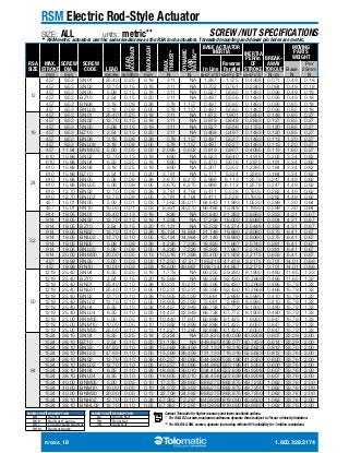
WHAT ARE THE RSA & THE GSA?
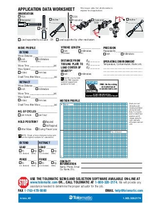
Flexibility defines the RSA and the GSA. Need a basic electric screw-driven rod-style actuator? Choose the RSA. Need a rod
style actuator that provides guidance and support for the load? Choose the GSA. Every actuator is built-to-order in the stroke
length you specify, shipped in 15 days or less. Motors can be mounted inline or reverse parallel to shorten the actuator.
Tolomatic offers brushless servo and stepper motors or supply your own motor and take advantage of our “Your Motor Here”
(YMH) program. Choose from 3 drive screw technologies with 12 different mounting and rod end options. All this backed by
over 50 years experience and our 100% satisfaction guarantee.
RP
MP2
LMI
GSA
FM2
RSA
CK
FFG
TRR
PCS
PCD
R/GSA_2 1.800.328.2174
BFG
YMH
YMH
ALC
CLV
MET
SRE
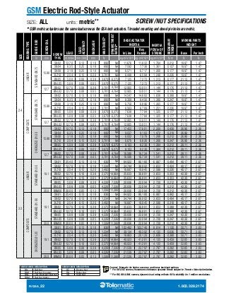
THE MODULAR FLEXIBLE DESIGN OF THE RSA & GSA, BUILT-TO-ORDER IN 15 DAYS
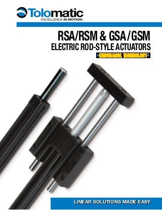
TOLOMATIC’S ELECTRIC ROD-STYLE ACTUATORS
ERD ICR RSA GSA IMA
Rod-Style Actuator Integrated Control
Rod-Style Actuator
Rod-Style Actuator Guided Rod-Style
Actuator
Integrated Motor
Rod-Style Actuator
Thrust up to: 4,500 lbf
[20,017 N]
720 lbf
[3,202.7 N]
12,900 lbf
[57,382 N]
4,159 lbf
[18,500 N]
6,875 lbf
[30,594 N]
Speed up to: 58 in/sec
[1473 mm/sec]
25 in/sec
[635 mm/sec]
123 in/sec
[3,124 mm/sec]
123 in/sec
[3,124 mm/sec]
52.5 in/sec
[1,334 mm/sec]
Stroke Length
up to:
39.4 in
[1000 mm]
24 in
[609 mm]
60 in
[1,524 mm]
36 in
[914 mm]
18 in
[457 mm]
Screw/Nut Type Solid, Ball & Roller Ball Solid, Ball & Roller Solid & Ball Ball & Roller
For complete information see www.tolomatic.com or literature number:
Literature Number: 2190-4000 2100-4000 3600-4609 3600-4609 2700-4000
(Not all models deliver maximum values listed, i.e.: Maximum thrust may not be available with maximum speed)](https://image.slidesharecdn.com/3600-416601rsa-gsa-141027091805-conversion-gate02/85/Electric-Rod-Actuator-Actuators-RSA-RSM-2-320.jpg?cb=1414404811)
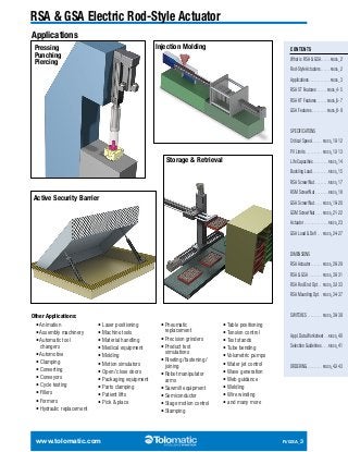
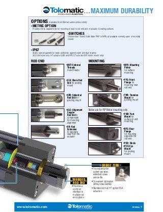
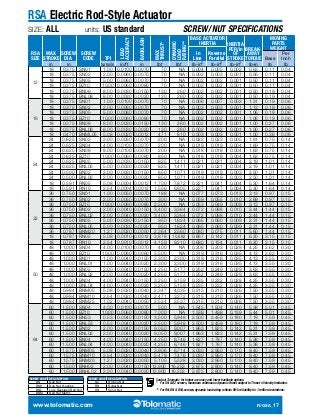
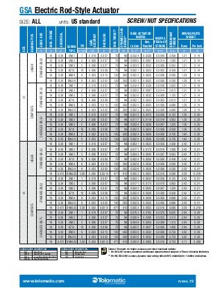
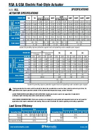
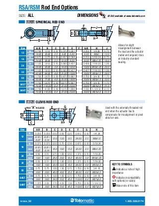
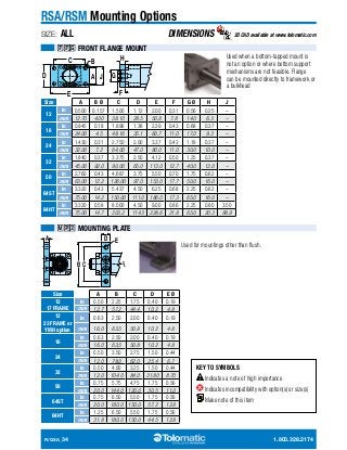
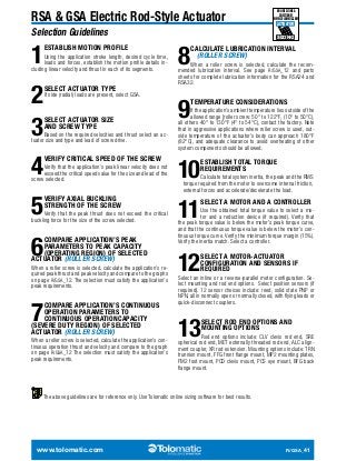
![RSA Rod-Style Screw Driven Actuator
SIZE: ALL
DIMENSIONS 3D CAD available at www.tolomatic.com
F
B AA
G+
CC
K
A
RR
D C
L
J
Motor
Motor
H+
STROKE
F E
STROKE
BB
EE EE
SS SS
G+
STROKE
K
J
SS
DD FF DD DD FF
DD
GG
E
LMI Motor Mount
H+STROKE
SS
JJ JJ
LL
HH
CL
RP Motor Mount
MM
KK
NN
Ø PP
Stub Shaft
LL
Motor
Motor
Motor
KK
Size G H
16
See table
at right for
BNML05
dimensions
*For
BN08
BNL08
only.
ACME NUT BALL NUT ROLLER NUT
BNML05
in 2.51 3.37
mm 63.8 85.6
ST ACTUATOR DIMENSIONS
Size A B C [4x] D E [2x] F G H G H G H J Ø K RR SS (2)
R/GSA_28 1.800.328.2174
12
in 0.906 0.391 5-40 0.50 1/4-28 0.75 8-32 0.25 0.81 2.17 2.76 2.17 2.76 NA NA 0.56 0.31 0.56 NA
mm 23.01 9.93 M3x0.5 12.7 M6x1.0 19 M4x0.7 6.3 20.7 55.1 70.1 55.1 70.1 NA NA 14.2 7.8 14.3 NA
16
in 0.500 1.063 8-32 0.50 5/16-24 0.75 8-32 0.25 1.06 2.13 2.99 2.13* 2.99* NA NA 0.69 0.43 0.69 NA
mm 12.70 27.00 M4x0.7 12.7 M8x1.25 19 M4x0.7 6.3 26.9 54.2 75.9 54.2* 75.9* NA NA 17.5 10.9 17.5 NA
24
in 0.875 1.603 10-24 0.79 7/16-20 1.00 1/4-20 0.33 1.11 2.90 3.84 3.36 4.30 4.54 5.21 1.18 0.43 1.96 NA
mm 22.23 40.72 M5x0.8 20.0 M10x1.25 25.0 M6x1.0 8.6 28.2 73.7 97.5 85.4 109.2 115.2 132.3 30.0 10.9 49.8 NA
32
in 1.181 1.969 1/4-20 0.70 7/16-20 1.13 5/16-18 0.47 1.43 3.87 5.05 5.05 6.23 6.05 6.85 1.25 0.50 1.29 1/16-27 NPT
mm 30.00 50.00 M6x1.0 18.0 M16x1.5 26.0 M8x1.25 12.0 36.3 98.4 128.3 128.3 158.2 153.6 174.0 31.8 12.7 32.8 1/16-27 NPT
50
in 1.969 3.000 5/16-18 1.00 3/4-16 1.50 3/8-16 0.75 1.95 4.78 6.44 5.78 7.44 NA NA 1.75 0.70 1.86 1/8-27 NPT
mm 50.00 76.20 M8x1.25 25.4 M20x1.5 38.0 M10x1.5 19.0 49.5 121.5 163.6 146.9 189.0 NA NA 44.5 17.8 47.1 1/8-27 NPT
64
in 1.969 3.500 7/16-14 1.50 3/4-16 1.50 7/16-14 0.88 2.37 6.94 8.90 8.94 10.90 NA NA 2.25 0.68 2.29 1/8-27 NPT
mm 50.00 88.90 M12x1.75 38.1 M27x2.0 38.0 M12x1.75 22.2 60.2 176.2 226.1 227.0 276.9 NA NA 57.2 17.3 58.2 1/8-27 NPT](https://image.slidesharecdn.com/3600-416601rsa-gsa-141027091805-conversion-gate02/85/Electric-Rod-Actuator-Actuators-RSA-RSM-28-320.jpg?cb=1414404811)
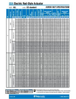
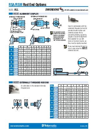
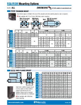
![RSA Rod-Style Screw Driven Actuator
DIMENSIONS 3D CAD available at www.tolomatic.com
ROLLER NUTS ALL OTHER NUTS
MM∞ NN PP
GG HH JJ KK∞ LL∞ GG HH JJ KK∞ LL∞
ST ACTUATOR DIMENSIONS
in 1.34 3.92 2.57 NA 1.13 0.500 8-32 0.25 NA NA NA 1.66 1.85 1.66 0.72 1.66 1.85 2.26 0.61 Ø.188
mm 34.1 99.6 65.3 NA 28.6 12.70 M4x0.7 6.3 NA NA NA 42.0 47.0 42.1 18.3 42.0 47.0 57.3 15.5 4.78
in 1.34 3.92 2.57 NA 1.13 0.500 8-32 0.25 NA NA NA 2.00 1.85 1.66 0.72 2.00 2.49 2.26 0.61 Ø.188
mm 34.1 99.6 65.3 NA 28.6 12.70 M4x0.7 6.3 NA NA NA 50.8 47.0 42.1 18.3 50.8 63.2 57.3 15.5 4.78
in 1.34 4.04 2.64 NA 1.38 0.500 8-32 0.25 NA NA NA 2.25 2.39 1.66 0.72 2.25 2.49 2.26 0.61 Ø.188
mm 34.1 102.7 67.0 NA 35.0 12.70 M4x0.7 6.3 NA NA NA 57.2 60.7 42.1 18.3 57.2 63.2 57.3 15.5 4.78
in 2.04 5.13 3.68 3.65 2.04 0.787 1/4-20 0.31 4.25 2.25 2.25 2.35 3.28 2.28 1.66 1.42 2.35 2.55 2.50 0.55 Ø.315
mm 51.8 130.2 93.4 92.6 51.8 19.98 M6x1.0 8.6 107.8 57.2 57.2 59.7 83.3 57.9 42.2 36.0 59.7 64.8 63.5 14.0 8.00
in 2.04 6.29 4.09 4.06 2.04 0.787 1/4-20 0.31 4.25 2.00 2.25 3.75 3.28 2.87 2.00 1.42 3.75 3.28 3.79 0.55 Ø.315
mm 51.8 159.8 103.9 103.2 51.8 19.98 M6x1.0 8.6 107.8 50.7 57.2 95.3 83.3 72.8 50.7 36.0 95.3 83.3 96.3 14.0 8.00
in 2.58 5.89 4.18 4.20 2.58 0.950 5/16-18 0.50 4.87 2.00 2.88 3.39 3.68 3.19 2.00 1.79 3.00 2.63 2.58 0.69 Ø.394
mm 65.5 149.6 106.1 106.7 65.5 24.13 M8x1.25 12.7 123.7 50.7 73.0 86.1 93.3 80.9 50.7 45.4 76.2 66.8 65.5 17.5 10.00
in 2.58 7.52 5.03 5.00 2.58 0.950 5/16-18 0.50 4.87 2.00 2.88 3.75 3.70 3.19 2.00 1.79 3.75 2.38 4.25 0.69 Ø.394
mm 65.5 190.9 127.8 126.9 65.5 24.13 M8x1.25 12.7 123.7 50.7 73.0 95.3 93.9 80.9 50.7 45.4 95.3 60.5 108.0 17.5 10.00
in 3.71 8.51 6.28 6.24 3.71 1.18 3/8-16 0.68 NA NA NA 3.00 3.30 3.60 2.22 2.13 3.00 3.30 3.69 1.36 Ø.500
mm 94.2 216.2 159.6 158.5 94.1 30.0 M10x1.5 17.5 NA NA NA 76.2 83.8 91.3 56.3 54.0 76.2 83.8 93.7 34.5 12.70
in 3.71 8.51 6.28 6.24 3.71 1.18 3/8-16 0.68 NA NA NA 3.00 3.05 3.60 2.27 2.13 3.95 3.05 3.69 1.36 Ø.500
mm 94.2 216.2 159.6 158.5 94.1 30.0 M10x1.5 17.5 NA NA NA 76.2 63.5 91.3 57.5 54.0 100.2 63.5 93.7 34.5 12.70
in 3.71 9.50 6.78 6.73 3.71 1.18 3/8-16 0.68 NA NA NA 3.00 4.48 3.60 2.52 2.13 5.00 4.48 5.58 1.36 Ø.500
mm 94.2 241.3 172.1 171.1 94.1 30.0 M10x1.5 17.5 NA NA NA 76.2 77.4 91.3 63.9 54.0 127.0 77.4 141.7 34.5 12.70
in 4.73 8.84 6.72 6.82 4.58 1.97 3/8-16 0.68 NA NA NA 3.75 3.05 4.73 2.75 3.48 3.75 3.05 4.48 1.36 Ø.750
mm 120.2 224.6 170.7 173.2 116.3 50.0 M10x1.5 17.5 NA NA NA 95.2 77.5 120.2 69.9 88.3 95.2 77.5 113.8 34.5 19.05
in 4.73 10.05 7.21 7.12 4.58 1.97 3/8-16 0.68 NA NA NA 5.00 4.48 4.73 2.85 3.48 5.00 4.48 5.73 1.36 Ø.750
mm 120.2 225.3 183.1 180.8 116.3 50.0 M10x1.5 17.5 NA NA NA 127.0 113.8 120.2 72.4 88.3 127.0 113.8 145.5 34.5 19.05
∞NOTE: YM code may change this dimension.
Always use configured CAD to determine critical dimensions
Size
Motor
Frame
AA BB
CC
1:1
CC
2:1
DD EE FF [2x]
12
17
23
16 23
24
23
34
32
23
34
50
23
34
56
64
34
56
HT ACTUATOR DIMENSIONS
Size
Motor
Frame
C [6x] BZ10 BALL NUTS BNM05/25
AA BB
CC
1:1
CC
2:1
GG KK∞ LL∞ MM∞ RR
C [4x] D G H G H G H L
32
23
in 1/4-20 0.70 7/16-20 1.13 NA NA 5.05 6.23 NA NA NA 2.58 5.89 4.83 4.80 3.19 3.46 4.14 2.58 1.29
mm M6x1.0 18.0 M16x1.5 28.7 NA NA 128.3 158.2 NA NA NA 65.5 149.6 122.8 121.8 80.9 87.9 105.1 65.5 32.8
34
in 1/4-20 0.70 7/16-20 1.13 NA NA 5.05 6.23 NA NA NA 2.58 5.89 4.83 4.80 3.19 3.55 4.10 4.25 1.29
mm M6x1.0 18.0 M16x1.5 28.7 NA NA 128.3 158.2 NA NA NA 65.5 149.6 122.8 121.8 80.9 90.0 104.2 108.0 32.8
50
34
in 5/16-18 1.00 3/4-16 1.45 NA NA 6.75 8.41 5.78 7.44 NA 3.71 8.51 6.68 6.62 NA 4.56 5.36 3.69 1.86
mm M8x1.25 25.4 M20x1.5 36.8 NA NA 171.5 213.6 146.9 189.0 NA 94.2 216.2 169.6 168.1 NA 115.8 136.2 93.7 47.1
56
in 5/16-18 1.00 3/4-16 1.45 NA NA 6.75 8.41 5.78 7.44 NA 3.71 9.50 6.68 6.62 NA 4.88 5.41 5.58 1.86
mm M8x1.25 25.4 M20x1.5 36.8 NA NA 171.5 213.6 146.9 189.0 NA 94.2 241.3 169.6 169.6 NA 123.8 137.4 141.7 47.1
64
34
in 1/2-13 0.75 1-1/4-12 2.50 7.80 9.29 10.25 11.74 NA NA 3.50 6.88 12.1 8.81 8.75 7.75 5.90 5.88 6.88 3.30
mm M12x1.75 18.0 M27x2.0 63.5 198.0 235.9 260.3 298.2 NA NA 88.9 174.6 306.1 223.8 222.3 196.9 149.9 149.3 174.6 83.8
56
in 1/2-13 0.75 1-1/4-12 2.50 7.80 9.29 10.25 11.74 NA NA 3.50 6.88 12.1 8.81 8.75 7.75 5.90 5.88 6.88 3.30
mm M12x1.75 18.0 M27x2.0 63.5 198.0 235.9 260.3 298.2 NA NA 88.9 174.6 306.1 223.8 222.3 196.9 149.9 149.3 174.6 83.8
Indicates dimensions are the same as ST1 actuators
www.tolomatic.com R/GSA_29](https://image.slidesharecdn.com/3600-416601rsa-gsa-141027091805-conversion-gate02/85/Electric-Rod-Actuator-Actuators-RSA-RSM-29-320.jpg?cb=1414404811)
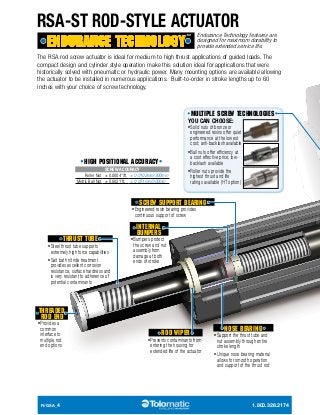
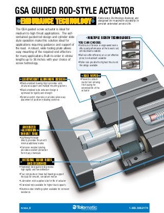
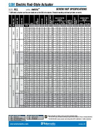
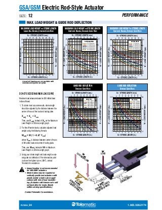
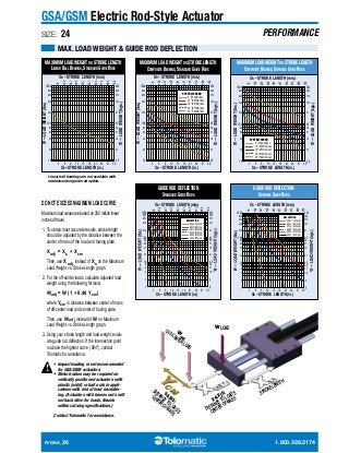
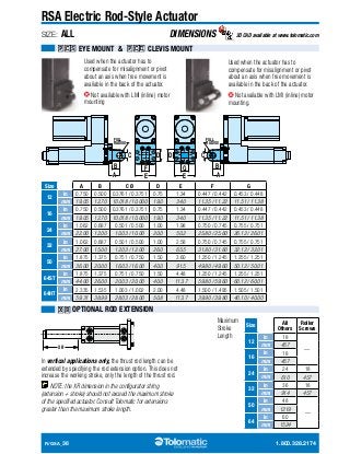
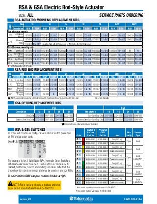
![GSA Electric Rod-Style Actuator
SIZE: ALL DIMENSIONS 3D CAD available at www.tolomatic.com
Y+
CC
CL CL
GG
D
A
B C
K L
EE
FF
W
V
N
R
P
S
T
X
M
U
JJ JJ
LL
HH
MM
Motor
Motor
Motor
Motor
R/GSA_30 1.800.328.2174
H
G
F
J
E
KK KK LL
BB
LMI Motor Mount RP Motor Mount
DD DD
CL
STROKE
CL CL
EE
FF
DD MM DD
Size A B C [4x] D E F G H J [4x]
12
in 5.13 2.000 1/4-20 Ø.38 0.22 OPP 0.688 0.88 4.00 2.500 0.750 Ø.266 Thru Ø.44 0.28 5/16-18 0.75 OPP
mm 130.2 50.80 M6x1.0 Ø9.5 5.6 OPP 17.46 22.4 101.6 63.50 19.05 Ø6.76 Thru Ø11.1 7.1 M8 1.25 OPP
16
in 6.25 2.500 5/16-18 Ø.44 0.28 OPP 1.000 1.13 5.00 2.625 1.188 Ø.266 Thru Ø.44 0.28 5/16-18 0.75 OPP
mm 158.8 63.50 M8x1.25 Ø11.1 7.1 OPP 25.40 28.6 127.0 66.68 30.18 Ø6.76 Thru Ø11.1 7.1 M8 1.25 OPP
24
in 7.75 3.500 5/16-18 Ø.44 0.28 OPP 1.375 1.38 6.00 3.875 1.063 Ø.328 Thru Ø.53 0.34 3/8-16 1.00 OPP
mm 196.9 88.90 M8x1.25 Ø11.1 7.1 OPP 34.93 35.1 152.4 98.43 27.00 Ø8.33 Thru Ø13.5 8.6 M10 1.5 OPP
32
in 10.00 5.000 3/8-16 Ø.53 0.50 OPP 1.750 1.63 7.00 4.125 1.438 Ø.453 Thru Ø.72 0.47 1/2-13 1.50 OPP
mm 254.0 127.00 M10x1.5 Ø13.5 12.7 OPP 44.45 41.4 177.8 104.78 36.51 Ø10.49 Thru Ø18.2 11.9 M12x1.75 OPP](https://image.slidesharecdn.com/3600-416601rsa-gsa-141027091805-conversion-gate02/85/Electric-Rod-Actuator-Actuators-RSA-RSM-30-320.jpg?cb=1414404811)
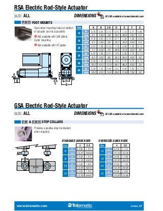
![GSA Electric Rod-Style Actuator
SIZE: ALL DIMENSIONS 3D CAD available at www.tolomatic.com
Size K L M Ø [2x] N P R S T Ø [4x] U V W X Ø [4x] Y
12
in 4.500 2.000 0.375 0.50 1.20 0.297 1.25 1.250 1/4-20 0.50 0.750 1.500 3.406 0.250 0.38 5.68
mm 114.30 50.80 10.00 12.7 30.5 7.54 31.8 31.75 M6x1.0 12.7 19.05 38.10 86.51 6.00 9.5 144.1
16
in 5.438 2.500 0.375 0.50 1.70 0.516 1.75 1.625 1/4-20 0.50 1.000 1.750 3.969 0.250 0.38 6.42
mm 138.13 63.50 10.00 12.7 43.2 13.11 44.5 41.28 M6x1.0 12.7 25.40 44.45 100.81 6.00 9.5 163.1
24
in 7.000 3.000 0.500 0.50 2.15 0.438 2.25 1.625 5/16-18 0.63 1.250 2.750 5.125 0.313 0.50 8.14
mm 177.80 76.20 12.00 12.7 54.6 11.13 57.2 41.28 M8x1.25 16.0 31.75 69.85 130.18 8.00 9.5 206.6
32
in 9.000 3.500 0.500 0.50 2.65 0.594 2.75 2.125 3/8-16 0.75 1.750 2.750 5.812 0.375 0.50 9.81
mm 228.60 88.90 12.00 12.7 67.3 15.09 69.9 53.98 M10x1.5 19.1 44.45 69.85 147.62 10.00 12.7 249.0
∞NOTE: YM
code may
change this
dimension.
Always use
configured
CAD to deter-mine
critical
dimensions
Size
Motor
Frame
AA BB
CC
1:1
CC
2:1
DD EE FF [2x] GG HH JJ KK∞ LL∞ MM∞
12
17
in 1.34 3.92 2.63
mm 34.1 99.5 66.9 28.6 12.70 M4x0.7 6.3 42.1 18.3 42.0 47.0 57.3
in 1.34 3.92 2.63 1.13 0.500 8-32 0.25 1.66 0.72 2.00 2.49 2.26
NA
mm 34.1 99.5 66.9 28.6 12.70 M4x0.7 6.3 42.1 18.3 50.8 63.2 57.3
1.13 0.500 8-32 0.25 1.66 0.72 1.66 1.85 2.26
23
16 23
in 1.34 4.04 2.88 1.38 0.500 8-32 0.25 1.66 0.72 2.25 2.49 2.26
mm 34.1 102.7 73.2 35.0 12.70 M4x0.7 6.3 42.1 18.3 57.2 63.2 57.3
24
23
in 2.04 5.13 3.78 3.75 2.04 0.787 1/4-20 0.31 2.28 1.66 1.42 2.35 2.55 2.50
mm 51.8 130.2 96.1 95.3 51.8 20.00 M6x1.0 8.6 57.9 42.2 36.0 59.7 64.8 63.5
34
in 2.04 6.29 4.20 4.17 2.04 0.787 1/4-20 0.31 2.87 2.00 1.42 3.75 3.28 3.79
mm 51.8 159.8 106.6 105.9 51.8 20.00 M6x1.0 8.6 72.8 50.7 36.0 95.3 83.3 96.3
32
23
in 2.58 5.89 4.26 4.28 2.58 0.950 5/16-18 0.50 3.19 2.00 1.79 3.00 2.63 2.58
mm 65.5 149.6 108.3 108.9 65.5 24.13 M8x1.25 12.7 80.9 50.7 45.4 76.2 66.8 65.5
34
in 2.58 7.52 5.11 5.08 2.58 0.950 5/16-18 0.50 3.19 2.00 1.79 3.75 2.38 4.25
mm 65.5 190.9 129.9 129.0 65.5 24.13 M8x1.25 12.7 80.9 50.7 45.4 95.3 60.5 108.0
www.tolomatic.com R/GSA_31](https://image.slidesharecdn.com/3600-416601rsa-gsa-141027091805-conversion-gate02/85/Electric-Rod-Actuator-Actuators-RSA-RSM-31-320.jpg?cb=1414404811)
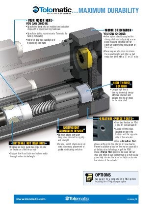
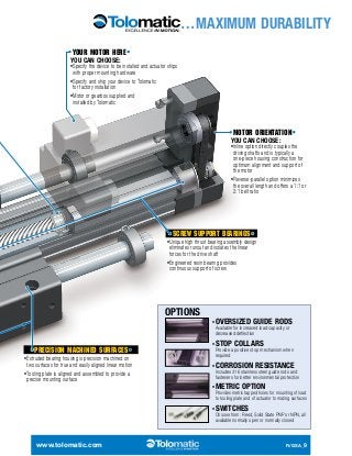
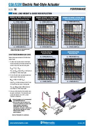
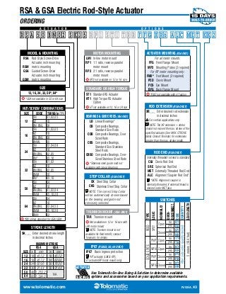
![RSA GSA Electric Rod-Style Actuator
SIZE: ALL
SWITCHES
COMPLIANT
Order
Code
Lead
Switching
Logic
Power
LED
RSA GSA products offer a wide range of sensing choices. There are 12
switch choices: reed, solid state PNP (sourcing) or solid state NPN (sinking);
in normally open or normally closed; with flying leads or quick-disconnect.
Commonly used for end-of-stroke positioning, these switches allow installation
anywhere along the entire actuator length. The internal magnet is a standard feature.
Switches can be installed in the field at any time.
Switches are used to send digital signals to PLC (programmable logic controller), TTL,
CMOS circuit or other controller device. Switches contain reverse polarity protection.
Solid state QD cables are shielded; shield should be terminated at flying lead end.
All switches are CE rated and are RoHS compliant. Switches feature bright red or
yellow LED signal indicators; solid state switches also have green LED power indicators.
Signal
LED
Operating
Voltage
**Power
Rating
(Watts)
Switching
Current
(mA max.)
Current
Consumption
Voltage
Drop
Leakage
Current
Temp.
Range
Shock /
Vibration
RoHS
REED
RY 5m SPST
Normally
Open
— Red
5 - 240
AC/DC
**10.0 100mA — 3.0 V max. —
14
to
158°F
[-10
to
70°C]
50 G /
9 G
RK QD* 81009082
81009082
81009082
— Yellow
81009082
81009082
81009082
81009084
81009084
81009084
81009084
81009084
Green Yellow
81009084
81009088
81009088
81009088
81009088
81009088
81009088
Green Red
81009090
81009090
81009090
81009090
81009090
81009090
81009092
Green Yellow
81009092
81009092
81009092
81009092
81009092
81009094
NY 5m SPST
Normally
Closed
5 - 110
AC/DC
NK QD*
81009094
SOLID
STATE
TY 5m PNP
(Sourcing)
Normally
Open
10 - 30
VDC
**3.0 100mA
20 mA
@
24V
2.0 V max.
0.05 mA
max.
TK QD*
Green Red
81009094
KY 5m NPN
(Sinking)
Normally
Open
KK QD*
81009094
PY 5m PNP
(Sourcing)
Normally
Closed
PK QD*
81009094
HY 5m NPN
(Sinking)
Normally
Closed
HK QD*
81009094
*QD = Quick-disconnect Enclosure classification IEC 529 IP67 (NEMA 6) CABLES: Robotic grade, oil resistant polyurethane jacket, PVC insulation
**WARNING: Do not exceed power rating (Watt = Voltage x Amperage). Permanent damage to sensor will occur.
SWITCH INSTALLATION
Place switch bracket into one of the four slots that run the length of the extruded tube.
Note that there is a cutout on the actuator head (RSA) or tube (GSA) to allow insertion
of the bracket. Insert the switch with the word “Tolomatic” facing up and slide it under
the bracket. Position the bracket with the switch to the exact location desired, then lock
them securely into place by tightening both set screws on the bracket.
R/GSA_38 1.800.328.2174](https://image.slidesharecdn.com/3600-416601rsa-gsa-141027091805-conversion-gate02/85/Electric-Rod-Actuator-Actuators-RSA-RSM-38-320.jpg?cb=1414404811)
![RSA GSA Electric Rod-Style Actuator
SIZE: ALL
SWITCHES
WIRING DIAGRAMS
RY, #8100-9082, • RK, #8100-9083
REED • NORMALLY OPEN
NORMALLY
OPEN
or
NORMALLY
OPEN
NY, #8100-9084, • NK, #8100-9085
REED • NORMALLY CLOSED
NORMALLY
CLOSED
or
NORMALLY
CLOSED
BRN
BLU
BRN
BLU
BRN
BLU
BRN
BLU
+
LOAD -
+
-
+
LOAD
LOAD -
+
-
LOAD
TY, #8100-9088, • TK, #8100-9089
SOLID STATE • NORMALLY OPEN • PNP
NORMALLY
OPEN PNP
(SOURCING)
BRN
BLK
+
SIGNAL
LOAD
BLU -
KY, #8100-9090, • KK, #8100-9091
SOLID STATE • NORMALLY OPEN • NPN
NORMALLY
OPEN NPN
(SINKING)
BRN
BLK
+
SIGNAL
LOAD
BLU -
PY, #8100-9092, • PK, #8100-9093
SOLID STATE • NORMALLY CLOSED • PNP
NORMALLY
CLOSED PNP
(SOURCING)
BRN
BLK
+
SIGNAL
LOAD
BLU -
HY, #8100-9094, • HK, #8100-9095
SOLID STATE • NORMALLY CLOSED • NPN
NORMALLY
CLOSED NPN
(SINKING)
BRN
BLK
+
SIGNAL
LOAD
BLU -
QUICK DISCONNECT MALE PLUG PINOUT #8100-9080 QUICK DISCONNECT
FEMALE SOCKET PINOUT
BLACK BLUE (-)
(SIGNAL)
BROWN (+)
BLACK
(SIGNAL)
BLUE (-)
BROWN (+)
SWITCH DIMENSIONS MOUNTING DIMENSIONS
_ Y - direct connect
DETECTION POINT
SOLID STATE
0.83 [21.1]
DETECTION POINT REED
_ K - QD (Quick-disconnect) switch
1.50 [38.2]
0.63 [16.0]
0.33 [8.4]
197.33 [5012]
This screw secures switch to bracket
This screw secures bracket to actuator
8100-9080 - QD Cable
1.26 [32.1]
.95 [24.1]
Ø.28 [7]
13.68 [347]
M8x1
M8x1
197 [5000]
A 1.50
B
0.29 [7.4]
www.tolomatic.com R/GSA_39
[38.2]
Ø.35
[9]
CAUTION: DO NOT OVERTIGHTEN SWITCH
HARDWARE WHEN INSTALLING
Size
A B
in mm in mm
12 0.68 17.2 0.13 3.3
16 0.77 19.6 0.11 2.9
24 1.06 26.9
0.06 1.5
32 1.31 33.2
50 1.87 47.5
64 2.31 58.6
Dimensions shown in inches [dimensions in brackets millimeters]](https://image.slidesharecdn.com/3600-416601rsa-gsa-141027091805-conversion-gate02/85/Electric-Rod-Actuator-Actuators-RSA-RSM-39-320.jpg?cb=1414404811)


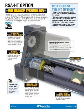
RSA/RSM Rod Actuator is a High Performance Electric Actuator Available in 6 Sizes The RSA/RSM electric rod actuators offer the most complete selection of sizes, options and system components. Designed with high performance, high thrust, dependability and mounting flexibility in mind, the RSA/RSM electric rod actuator offers a cost-competitive solution for a multitude of motion control applications. 6 body sizes 35 different screw selections Thrust capabilities up to 12,900 lbf (57,392 N) Strokes in any incremental length up to 60 in (1,524 mm) US conventional and metric versions


