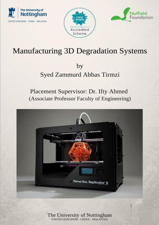
2. Manufacturing 3D Degradation Systems Student Name: Syed Tirmzi
2
Table of Contents
Abstract..................................................................................................................................................3
Introduction...........................................................................................................................................3
Project Aims and Objectives...............................................................................................................4
Planning of the project........................................................................................................................4
Research based on 3D Printer and the degradation system project.....................................................5
Types of 3D printers .......................................................................................................................6
How a RepRap 3D printer does works?..........................................................................................6
Glass microspheres, PBS and SBF .....................................................................................................7
Microfluidic Chip/ Embryo Immobilization Chip /MI2
Chip..............................................................8
Methodology..........................................................................................................................................8
Process of printing a 3D object...........................................................................................................8
1) Designing a CAD model in Sketch up or in any other CAD software....................................8
2) Using Netfabb Software and then slicing the file using Repetier-Host ................................10
3) Cleaning the printing bed to get the best 3D printing results ...................................................12
Initial Ideas for Task 1 Project..........................................................................................................14
Initial Ideas for Task 2 Project..........................................................................................................16
Final Degradation Task 2 Sketch......................................................................................................18
CAD Designing for Task 1 Project...................................................................................................19
3D Printing Results and Evaluation..................................................................................................19
Improved CAD Design for the Task 1 project..................................................................................20
Repairing Manifold errors through Netfabb of the improved CAD Design .....................................21
Printing Improved Task 1 CAD Design............................................................................................22
Final 3D Printed Degradation System Picture.................................................................................22
Further Evaluation and Analysis.......................................................................................................24
Help and support during the project.................................................................................................25
References............................................................................................................................................26
Image References:.............................................................................................................................26
Bibliography........................................................................................................................................26
Acknowledgment.................................................................................................................................27
3D Printed by Syed Tirmzi.................................................................................................................28
3. Manufacturing 3D Degradation Systems Student Name: Syed Tirmzi
3
Abstract
In my Nuffield research placement I worked with Dr. Ifty Ahmed and members of his PhD research
team on 3D printing engineering. I started my placement by learning how to draw CAD models using sketch up
and then later on I learnt how to use CAD models to print them in 3D using a 3D Plastic Printer. I used the help
of internet and some tutorial videos to learn how to use a 3D printer. After printing some 3D designs then my
supervisor gave me two tasks to complete during my placement.
My research placement was based around designing and then manufacturing two degradation systems
for Dr. Ifty and his Phd research team. The main aim behind my degradation systems is to allow my supervisor
to observe the reaction between his small degradable samples and the fluid. As explained by my supervisor
normally observing the reaction between their sample and fluid gives inaccurate results. The main reason behind
the inaccuracy of these results is due to handling and reacting the samples using a wrong method.
My main aim behind this project is to find a solution for this issue as after this placement in future by
using my manufactured degradation systems Dr. Ifty and his PhD research team will be able to get more
accurate degradation results. I started my project through questionnaires which allowed me to get some wider
knowledge about my project. My online research related to Embryo Immobilization Chip and Small
Degradation Systems allowed me to developing drawings for my project in Sketchup. Later on during
manufacturing of my tasks I used trial and error method to improve my design.
Introduction
My main aims behind my research placement were to learn how to use Sketch up to make a 3D CAD
(Computer Aided Design) design, to learn how to use a 3D printer to print a 3D model, to design two 3D
degradation systems for a PhD research team and to manufacture designed degradation systems using a 3D
printer. When I started my project I had a little bit knowledge of CAD designing in Sketch up (Google’s CAD
software) through my GCSE Resistant Material Coursework. I started making my CAD designs using my
previous knowledge and through learning from tutorials available online. My supervisor guided me to do some
extra research on small degradation systems, flow systems, microfluidic chips and Embryo chip during the first
week of my placement. My project is mainly based around my all researched topics.
My first task was to work on manufacturing a small chip similar to MI2 chip but for degradation
purpose. My supervisor gave me some research directions in my second week from where to start and then I
designed the chip using the 3D printer knowledge which I gained earlier in my first week. My second task was
to design and manufacture a degradation system using a 3D printer. I started working on my both tasks through
a questionnaire in which I asked Dr. Ifty (my supervisor) and members of his PhD research team some questions
related to both degradation systems like What is the main purpose should be? What the dimensions should be?.
Once I got all the answers then I started making some initial designs on paper and on a CAD software
called Sketch up. My supervisor gave me some researching task related to my project which allowed me to
develop my design. I started my research on Embryo Immobilisation Chip and the design of my first
degradation project is also inspired by Embryo MI2
Chip. I finalised my designed with my supervisor and then
started making them using a 3D printer.
I started with printing a prototype of my first design which failed because of a software issue in the 3D
printer. Then I printed the second prototype of my first task and it printed it successfully but it failed to print the
holes inside chip because our 3D printer has lower resolution printing. I changed the dimensions and it printed it
perfectly. I didn’t get a chance to print my second task as I ran out of time and the 3D printer broke down due to
a blockage inside the extruder of the 3D printer.
4. Manufacturing 3D Degradation Systems Student Name: Syed Tirmzi
4
Project Aims and Objectives
My main aims and objectives from my placements are,
Learn and experience how Engineers use their wide knowledge to find solution
Learn how to use a 3D printer and print 3D objects
Learn how to do CAD designing and then repairing the STL. File
Design and manufacture 3D degradation systems
Test and then improve the design of the degradation systems
Experience how to work in a team by asking help and support from different people working around
Write a scientific report on the project
Planning of the project
I decided to start my project with some research related to my project especially related to
degradation systems. In order to get a perfect idea of a degradation system which I need to design for
Dr. Ifty and his research team I decided to do a Questionnaire. After getting all initial ideas then start
learning how to do CAD designing and how to use a 3D printer to print an object. In order to learn the
3D printer use online tutorials. My mentor taught me that one of the main skills of working in the
field of Engineering is trial and error.
Print some 3D objects using the 3D printer to get more experience. After learning how to use
a 3D printer design your initial sketches on CAD (Sketch up) and then print them. Improve your
design after discussing them with PhD Research team so it can meet their required standard.
Objectives Timetable
Week Task / Objectives to complete
Week 1
*Complete the research on 3D printers and samples related to the project.
*Start learning how to use Sketch Up for CAD designing.
*Learn how to use a 3D RepRap Printer to print STL. Files
*Learn different skills used in daily Engineering from my mentor and the
members of the PhD research team.
Week 2
*Complete the Questionnaire related to the degradation project after the
meeting with mentor.
*Start drawing initial sketches of the degradation system using pencil.
*Print some 3D STL. files to get more experience with 3D printers.
Week 3
*Start drawing the initial sketches on CAD (Sketch up software).
*Do the mathematical calculations or further required research related to
the degradation project.
*Print some designed prototypes for the initial testing.
*Start writing you project report.
Week 4
*Improve your degradation system design after testing and discussing it
with the research team.
*Do some final testing of the 3D degradation system.
*Finalise your project report.
5. Manufacturing 3D Degradation Systems Student Name: Syed Tirmzi
5
Research based on 3D Printer and the degradation system project
In order to start my placement I did some research on the topics related to my placement. I started my
research from the 3D printer engineering which was the main focus of my research and then later on moved to
design and samples of my project.
I choose 3D Printing Engineering as my research placement because this placement does not only
allow me to cover 3D Engineering but it also allows me to deal with materials engineering. Printing 3D
degradation systems will allow me to learn new skills and give me an experience how to use thinking skills to
solve engineering problems. In normal school education we study maths, physics and chemistry as separate
subjects but this engineering project is a way to show me how to combine and use all education fields to find
solutions in practical engineering life.
I decided to use internet as the main source of gaining knowledge about 3D printing because of its
quicker access and the availability of online 3D printing tutorials. The other ways of doing my placement were
to read 3D printing engineering books, printing manuals or scientific articles but due to short availability of time
I decided to use internet research. Internet research is not only quicker but it’s also the most updated source.
Most of the problems which I came across during my placement were issues related to 3D printer and in that
case 3D Printing online forums proved as the best way of finding quick 3D printing solutions. I also decided to
shadow the research team other than my project based in University of Nottingham to learn university
engineering skills like how to approach a problem and find it’s solution through using engineering knowledge.
Fig. 1.0 3D Printer BCP-01
Filament (PLA/ABS)
Back Fan for Cooling
Printing Bed
Filament Extruder
3D Printed Object
Printing Bed
z-axis
G-Code Commands
sent through here
Extruder Fan
6. Manufacturing 3D Degradation Systems Student Name: Syed Tirmzi
6
Types of 3D printers
There are many type of 3D printers available in the market from the plastic and rubber 3D printers to
metal 3D printers. The plastic 3D printers I used during my placement used Fused Filament Fabrication
Technology (FFF) to print the model in 3D. In this technology the extruder extrudes the plastic filament in
forms of small beads which hardens immediately to form the layer.
The other most advanced 3D metal printers use different type of methods to
print a 3D metal object. The metal 3D printer which I remember from my visit to Renishaw headquarters as
shown in Fig. 1.1 uses Selective Laser Sintering (SLS) in order to print a metal object. In SLS printing as shown
in Fig. 1.2 metal powder is mainly used. A roller supplies the metal powder to the printing bed (fabrication
piston bed) where laser is used to fuse metal powder particles together. Commands are sent to the scanner
system to tell where to point the laser. Once the layer has been made then the fabrication piston move
downwards so that another layer can be made and this process is repeated until all layers has been made.
Fig. 1.1 Renishaw Metal 3D Printer Fig. 1.2 Selective Laser Sintering method
How a RepRap 3D printer does works?
In order to learn how to use a 3D printer it’s essential to learn how the 3D printer actually works. I used a
RepRap ( Replicating Rapid Prototype) BCP – 01 3D printer during my research placement. A 3D printer prints
the object in layers using a G-code file which contains set of instructions for the 3D printer. It can be loaded on
the printer using a computer or a micro sd card. As shown in Fig. 1.0 loaded filament is released through the
extruder which can move in x,y or z-axis. The hot extruder melts the filament and releases it on to the hot
printing bed. This filament printed in layers is then cooled extruder fan and the printing bed fan. This process of
releasing the filament through the extruder to print it on the printing bed is called Fused Filament Fabrication
(FFF).
7. Manufacturing 3D Degradation Systems Student Name: Syed Tirmzi
7
Glass microspheres, PBS and SBF
When I did a questionnaire with Dr. Ifty and his research team that time I asked them what type of
sample and fluid they are going to test in my designed 3D degradation system. Glass microspheres are the
samples which they will try to react with different fluids like with PBS (Phosphate Buffered Saline) and
SBF(Simulated Body Fluid).
Glass microspheres as shown in Fig. 1.3/14 are mainly used in medicines and research projects. They
are available in different sizes in the market their diameters ranging from 100 nanometres to 5 millimetres. The
one which Dr. Ifty and his research team will use are going to have a diameter of less than 1 millimetres.
Phosphate Buffered Saline and Simulated Body Fluid are fluids which Dr. Ifty and his research team will use in
degradation process of glass microspheres.
Fig. 1.3/1.4 Glass Microspheres
PBS is the buffered solution(An aqueous solution consisting of a weak acid and its conjugate base)
which is used in Biological Research. PBS is mainly used as substance dilution because of its non-toxic
properties. According to an online published article “SBF is a solution with an ion concentration close to that of
human blood plasma”. SBF is used in dissolution testing (testing drugs quality through dissolving them).
Fig. 1.5 Phosphate Buffered Saline (PBS)
8. Manufacturing 3D Degradation Systems Student Name: Syed Tirmzi
8
Microfluidic Chip/ Embryo Immobilization Chip /MI2
Chip
Design for my first task is inspired by the Embryo Immobilization Chip (MI2
). I decided to do some
basic research on Microfluidic Chip and MI2
Chip before starting my project. Microfluidic Chip also known as
lab on a chip carries out several laboratory tasks only on a small single chip as shown in Fig. 1.6. They can be
used for different type of functions like sort, pump and mix depending on the requirement.
Embryo Immobilization Chip (MI2
Chip) as shown in Fig. 1.7 is a type of a microfluidic chip. It is used
for the observation of embryos as it provides live imaging with a high resolution. Live imaging used to be very
difficult because of the movement of the samples during handling but MI2
Chip has solved this problem. I
decided to use the same design considering that it will allow Dr. Ifty and his research team to observe the
samples in a really high imaging quality. The Embryo Immobilization Chip contains over 250 well chambers for
the embryos.
Fig. 1.6 An example of a microfluidic chip Fig. 1.7 Embryo Immobilization Chip
Methodology
Process of printing a 3D object
1) Designing a CAD model in Sketch up or in any other CAD software
In order to print an object first you need to design it in 3D using a CAD software like Sketch up,
Autodesk or any other available software. I used Sketchup by Google during my placement to design
my tasks. Google Sketchup exports an STL (Standard Triangle Language) file which stores all the
Well Chambers
Well Chambers
STL Model
ModelModel
Fig. 1.8 Difference between a CAD
model file and a STL file
CAD Model
Model
9. Manufacturing 3D Degradation Systems Student Name: Syed Tirmzi
9
information related to the surface geometry of the designed product. STL files can be stored as Binary
or ASCII (American Standard Code for Information Interchange). STL files store the surface geometry
information as triangles as shown in Fig. 1.8.
Fig. 2.0 CAD design for my Task 1 Degradation System
Fig. 1.9 CAD design in Sketch up for a Rolls Royce Model Engine 3D stand
10. Manufacturing 3D Degradation Systems Student Name: Syed Tirmzi
10
2) Using Netfabb Software and then slicing the file using Repetier-Host
Once the CAD file has been exported as an STL file then you needs to check the file for any
manifold errors. Netfabb is the free online software available to repair the file if it contains any
manifold error. It analyses the STL file by running the test run on it and then repairs the faulty parts.
The main reason behind the popularity of the free version of Netfabb is because it offers automatic part
fixing and mesh editing.
Fig. 2.1 Screenshot Showing my designed model stand STL files in Netfabb with errors
Fig. 2.2 Repaired model stand file in Netfabb
Dimensions of the actual model
Test run option
Red Highlighted parts which needs repairing
Option to scale the model
Camera View of the object
x, y or z-axis Pointing those defects has been found in the object
Green – part with no errors
Align Parts Option
11. Manufacturing 3D Degradation Systems Student Name: Syed Tirmzi
11
After applying the repair option on the file then it’s exported as an STL file through the part option.
Repaired STL file is then opened into the Repetier-Host Software in order to slice it and then make a G-code
file. Repetier-Host Software is mainly used to communicate between the software and the 3D printer through a
G-code.
Fig. 2.3 Model Stand file opened in Repetier-Host for Slicing
Slicer takes the STL file to translate it into layers and then outputs the machine code which is known as
G-code. Slicer settings allow user to set up fill density, fill pattern, head speed, extrusion speed and support
material.
Fig. 2.4 Sliced File Information Fig. 2.5 Printer Settings
Load STL File from here
Slice the object
Open the Slicer Window through Configuration button
Slicer Settings
Layer Visualization Option
Manual control for the extruder movement
12. Manufacturing 3D Degradation Systems Student Name: Syed Tirmzi
12
We can also visualize the object layer by layer using the Repetier-Host to get an idea how the 3D
printer will print the object. We can either send the file direct for the print or we can save it on a sd card to print
it later on. Manual Control in the Repetier-Host allow us to control the 3D printer. We can control the extruder
movement in x, y or z-axis. We can also control the feed rate which is the speed of the extruder to print the
layers. We can control the fan speed which relates to the cooling of the printed object as for different objects
different fan speed settings are required to get an optimal result. I mainly used the fan speed of 100 while
printing my projects. We can also control the Bed Temperature and the extruder temperature. Increasing the
extruder temperature will also result in increase in the flow rate of the filament.
After slicing the file as shown in Fig. 2.6 It can be sent straight to the printer for the printing. The 3D
printer will first heat the bed and the extruder up to the set temperature like I used 60.0 °C for the bed
temperature and 220.0 °C for the extruder temperature during the printing of my project.
3) Cleaning the printing bed to get the best 3D printing results
In order to get the best 3D printing result you must ensure that the printing bed must be clean
before printing. You must wear laboratory gloves, laboratory coat and safety glasses considering safety
precautions as shown in Fig. 2.7. It is essential to check the bed temperature before touching it otherwise you
may burn your hand.
Fig. 2.7 Laboratory Safety precautions must be observed while working
Skirt – ensures material is flowing
smoothly before start printing
Support Material for printing
Sliced Layers can be seen
Fig. 2.6 Ready to print Sliced
STL File of the model stand
13. Manufacturing 3D Degradation Systems Student Name: Syed Tirmzi
13
Clean the printing bed using Acetone cleaner as it cleans the printing bed by dissolving any plastic
or glue present on the bed. Once the bed has been cleaned using the cleaner then spray the hairspray on the bed
as shown in Fig. 2.8. We spray hairspray on the bed surface as it strengthens the adhesion between the object
being printed and the printed bed. Adhesion can also be strengthened by increasing the bed temperature.
Fig. 2.7 Cleaning the bed using the cleaner Fig. 2.8 Spraying hairspray on the bed
Questionnaire for Task 1 and Task 2 Projects
In order to start drawing sketches of my project I decided to do a questionnaire with Dr. Ifty and his
research team. In this questionnaire I asked them following questions,
How many 3D degradation systems they want me to manufacture?
We want you to manufacture two 3D degradation systems for us. These degradation systems will
allow our two different samples to get degraded with our fluids.
What type of samples they will use in those degradation systems?
We will use Glass Microspheres/Micro beads in the first degradation system project which have the
diameter of less than 1 millimetre. In the second degradation system we will use some cylindrical samples which
has the height of 10 millimetres and the diameter of 10 millimetres.
Fig. 2.9 Glass Micro beads for Task 1 Fig. 3.0 Cylindrical samples for Task2
Diameter of less than 1mm
14. Manufacturing 3D Degradation Systems Student Name: Syed Tirmzi
14
What type of fluids they will use in those degradation systems?
We will use water, PBS (Phosphate Buffered Saline) and SBF (Simulated Body Fluid) with our
samples.
Is it good if I try to make a flow system for the fluids in those degradation systems?
If you manage to design an automated flow system in your degradation system then it will be perfect. It
will reduce the errors caused by handling the samples resulting in more precise degradation results. Remember
to do some research on flow inlet and outlet when you design the flow system.
Do you have any preferable design or idea for these degradation systems?
We want you to do some research on Microfluidic Chip and Embryo Immobilization Chip as it may
help you to design your first degradation system.
Initial Ideas for Task 1 Project
I sketched an initial design as shown in Fig. 3.1 for my task 1 degradation system. It is inspired by the
design of the Embryo Immobilization Chip. I kept this sketch really simple by showing a cube shaped system
with a 13mm radius circle space for well chambers. I also showed the pipe connectors for the flow system and
made them detachable. The reason I made the pipe connectors detachable because I was thinking to make my
project as modular. A modular degradation system would allow the user to connect more systems with it
depending on the need as if he/she got more samples to test then he can easily attach two or more systems
together.
I discussed my initial design with my supervisor and the main problem with my design was the flow
system. The pipe connectors in the drawing were the same dimensions as the side of the degradation system but
with these dimensions the flow would be so high. The high flow system means that it would be really difficult
for our glass micro beads to stay stationary resulting in poor live image view.
Fig. 3.1 First Task Degradation System initial sketches
Cylindrical pulled circle
space for well chambers
Pipe connectors for the
fluid flow system
Detachable Slide Pipe
Connectors
15. Manufacturing 3D Degradation Systems Student Name: Syed Tirmzi
15
In the meeting with my supervisor I also found out that I need
to decide how many well chambers I am going to manufacture in the
cylindrical space. To start with some rough idea I decided to use some
mathematics skills here. I calculated the total area( 𝐴 = 𝜋𝑟2
) for the big
circle which has the radius of 13mm. The area for the bigger circle is
530.998 mm2
.
Then I calculated the area for the smaller circle with the radius of 0.5mm. The area of the smaller circle
is 0.7855 mm2
. The calculated area can tell that how many well chambers I can fit in the big circle.
530.998/0.7855 = 676 well chambers. This gives us a rough idea that we can fit almost 676 well chambers. In
the actual design there will be fewer well chambers as we will need to consider the gaps
between each well chamber as well and how they are going to be manufactured to give
out the best possible degradation results.
Drawing showing the calculations to calculate the
number of well chambers that can be fit in the area.
Fig. 3.2 Showing diameter of the cylindrical pulled space
Drawing showing the cross-
section of the designed chip
cylindrical area.
Fig. 3.3 Showing design of a well chamber
16. Manufacturing 3D Degradation Systems Student Name: Syed Tirmzi
16
After the meeting I decided to do some changes in the flow system. Instead of using really large pipe
ends and modular system I decided to use the pipes with the diameter of 3mm as shown in Fig. 1.14 below. I did
some research on pipe new inlet and outlet for the flow. The position of flow inlet and outlet is really important
as if the fluid enters from the top and leaves from the bottom then it will never result in a continuous flow and it
won’t fill the degradation system. I decided to use the bottom pipe as the flow inlet and the top pipe for the flow
outlet.
Fig. 3.4 Improved design for the first degradation system
Initial Ideas for Task 2 Project
My second degradation project was to manufacture another 3D degradation system
for some cylindrical samples. After the questionnaire I presented some ideas to Dr. Ifty and
his research team for discussion on the second project. I also decided to make a fluid flow
system for this degradation project as well.
This is the first idea
which I presented to the research team. In this idea I
planned to make a big box with dimensions of 110
mm length, 50 mm width and 60mm height. The
box would have three cylindrical spaces for the
samples and for those spaces I
designed the base as shown in
Fig. 3.6 to hold the cylindrical
samples.
Blue Lines Showing the fluid
flow system
Fig. 3.6 Showing the close up of the base
which would hold the cylindrical smaples
Fig. 3.5 Design of a cylindrical
sample
17. Manufacturing 3D Degradation Systems Student Name: Syed Tirmzi
17
This is another sketch of the degradation system in
which I thought to design the cylindrical wells horizontally
instead of making them vertically. In the cylindrical wells I also
made small holding points so the fluid can degrade the sample
fully.
In this design it’s a hollow big cylindrical with
small cylindrical spaces for the samples in it. Small
cylindrical spaces for samples are supported with the
walls of the big hollow cylinder.
This idea is similar to the first one but in
this one it has the different flow system. In this
degradation system flow will enter from the
bottom of each cylindrical well and it will from the
top.
Small holding points
18. Manufacturing 3D Degradation Systems Student Name: Syed Tirmzi
18
Final Degradation Task 2 Sketch
After presenting all my previous designs and discussing their advantages or disadvantages in the meeting we
selected one final design for my task 2 degradation system. I presented this design to the research team which
consists two parts of a degradation system. The first part is a big shaped box for the fluid flow and the second
one is for the samples.
The dimensions for the box are 150 mm
length, 100mm width and 50mm height. The
inner space dimensions are 130 mm length,
40 mm depth and 80 mm width. I changed
the flow system later on by connecting 10
mm diameter pipes on each side.
This is the second part of this degradation
system which will hold the 10mm x 10 mm cylindrical
samples to degrade them with the fluid. It has 150 mm
length and on each side there is 100 mm wide support.
Support will be placed on the sides of the big
rectangular fluid box. I designed three cylindrical
sample holders as my supervisor (Dr. Ifty) wanted me
to design a triplet degradation system.
The cylindrical sample holder has the
diameter of 20 mm and 20 mm depth. I designed
different type of sample holders and decided to go
forward with the second one. It’s design is inspired
by the normal basket bucket design and it will allow
the best flow of the fluid through the samples for
complete degradation.
Support
19. Manufacturing 3D Degradation Systems Student Name: Syed Tirmzi
19
CAD Designing for Task 1 Project
I started making my CAD design in the sketch up of my final design for the first degradation system
(Pg. 15). I started with the dimensions 30mm length,
30mm width and 30mm height and the cylindrical
space of 28mm diameter for the well chambers. I
decided to start printing the side holes for the pipe with
3mm diameter.
I started with printing 1mm hole as I
wasn’t sure what is the smallest possible hole which
our printer could print. The top side hole for the
pipe flow system is at 26.5mm from the base and it
has the diameter of 3mm. The bottom side hole for
the pipe flow system is at 14.5mm from the base
and it has the diameter of 3mm.
3D Printing Results and Evaluation
My first print failed as 3D printer extruder jammed. After doing some research I found out from the RepRap
official website that “”Leaving printer extruder heated up for 20minutes or more without extruding the extruder
jams” and the solution for this problem is to “Limit extruder hot time and extrude 10mm every 10 minutes”.
91 Well Chambers
Top Side hole for the
pipe flow system
Fig. 3.7 Side view in CAD of
designed degradation system
Fig. 3.8 Top view in CAD of
designed well chambers
Fig. 4.0 Extruder
Fig. 3.9 Failed Print
20. Manufacturing 3D Degradation Systems Student Name: Syed Tirmzi
20
I fixed the jam and then successfully printed my first prototype as you can see in the images. It printed
all the right dimensions of my prototype but through first print I discovered it failed to print the well chambers.
The main reason behind this failure was the lower resolution printing of the 3D printer.
Improved CAD Design for the Task 1 project
I decided to improve my Task 1 Degradation system design after the well
chambers failure. I added the pipes for the flow system in the new CAD design and changed the dimensions of
the degradation system as well. New degradation system has 60mm length, 60 mm width and 50mm height. The
pulled circle for well chambers has the diameter of 50mm and the depth of 25mm. I changed the dimensions for
the well chambers as well considering the resolution of the 3D printer to the diameter of 2mm and the depth of
3mm.
Fig. 4.1 Task 1 Degradation System Test print
Fig. 4.2 Improved design of degradation system
21. Manufacturing 3D Degradation Systems Student Name: Syed Tirmzi
21
I designed the threaded (tapered) pipe to
help the research team in connecting the fluid pipes
to this degradation system. The top side pipe is
located 43mm from the base and the bottom side
pipe is located 30mm from the base.
Repairing Manifold errors through Netfabb of the improved CAD Design
I checked the file through netfabb for any manifold errors in my CAD before transporting to Repetier-
Host software as a STL. file for printing. All the red shaded triangles in pipe connector show manifold errors. I
did some research to resolve the issue as netfabb didn’t repair them through automatic repair. I used fix flipped
triangles option to fix the issue by selecting each triangle and then applying the option. The main problem
behind manifold errors was that the triangles were flipped.
Showing the inner geometry of the designed pipe
Zoom view of the designed pipe
Fig. 4.3 Improved design of degradation system
Fig. 4.4 Repairing CAD file in Netfabb Software
22. Manufacturing 3D Degradation Systems Student Name: Syed Tirmzi
22
Printing Improved Task 1 CAD Design
After repairing my STL. File in netfabb I transferred it to Repetier-Host to make a G-code file. I added
support to my degradation system and then sliced it using slicer. I decided to print the rectilinear fill pattern
which took 4 hours and 26 minutes to print my project. After printing the degradation system I kept it in hot
water for about 6-7 hours to dissolve the 3D printing supports.
Final 3D Printed Degradation System Picture
Support Material
Rectangular
Structure
Skirt/Brim
Fig. 4.5 Sliced CAD file opened in Repetier - Host
Fig. 4.6 3D Degradation System Printing Stages
23. Manufacturing 3D Degradation Systems Student Name: Syed Tirmzi
23
Well Chambers
Flow OutletFlow Inlet
Fig. 4.7 3D Printed Degradation System
Fig. 4.8 3D Printed Degradation System top
view of Well Chambers
Fig. 4.9 Top Side View of the 3D printed
Degradation System
24. Manufacturing 3D Degradation Systems Student Name: Syed Tirmzi
24
Further Evaluation and Analysis
After printing my final Task 1 3D degradation system I tested it and found out some
areas which needs improvement. As there wasn’t enough time available to reprint it after correcting
the errors so I decided to include them here. Due to lower resolution printing it didn’t print the flow
inlet/outlet pipe connectors correctly. Fig. 5.0 shows the design of the pipe connector I designed and
what it was supposed to print but Fig. 5.1 clearly shows 3D printer missed all the design details. In
order to avoid this error in future I would strongly recommend either using a 3D printer with a higher
resolution or rescaling the connector. This error in flow pipe connector printing may lead to leak of
fluid during testing in result giving inaccurate results.
Another problem I faced was snapping of filament when I was printing my project as I was
using PLA. I decided to use ABS Filament in the end after doing some research on the internet about
the 3D printer filaments. I found out that ABS filament is more flexible than PLA so it doesn’t snap
easily as shown in Fig. 5.3. PLA filament is brittle so it snaps easily as shown in Fig. 5.2.
I didn’t get a chance to print the second degradation system as my placement finished and the
3D printer software broke down. I tried to fix the 3D printer software when I was leaving by working
with one of the university technician but we failed to fix it due to some software installation
restrictions by University IT Services.
Fig. 5.0 Fig 1 Pipe connector design it was
supposed to print
Fig. 5.1 Pipe connector design it printed
25. Manufacturing 3D Degradation Systems Student Name: Syed Tirmzi
25
Help and support during the project
While doing my Nuffield placement at University of Nottingham there were various
occasions when I needed help and support from different people working around me. Through this
placement I found out the best way to find a solution is if you are stuck somewhere then start with
searching in either books or internet for the solution, if you are unable to find the solution then ask the
members of PhD research team but if you are still stuck then contact your mentor.
I spent first week of my placement with my one of my colleague Mr. Adam who had
experience in CAD designing and 3D printing. I always used to ask him if I used to get stuck
somewhere with 3D printing and can’t find any solution. My mentor Dr. Ifty also introduced me to
one of the University Technician (Mr. Jason) who helped me a lot in solving out the issues which I
faced with the 3D printer during my placement. The best way to contact these people regarding help
was through email and then request to see them if needed depending on the problem.
Fig. 5.2 PLA Filament Fig. 5.3 ABS Filament
Brittle
Flexible
27. Manufacturing 3D Degradation Systems Student Name: Syed Tirmzi
27
http://reprap.org/
https://en.wikipedia.org/wiki/RepRap_Project
https://en.wikipedia.org/wiki/3D_printing
http://www.protoparadigm.com/news-updates/the-difference-between-abs-and-pla-for-3d-printing/
https://en.wikipedia.org/wiki/Selective_laser_sintering
https://en.wikipedia.org/wiki/STL_(file_format)
http://www.protoparadigm.com/news-updates/3d-printer-filament-buyers-guide/
https://en.wikipedia.org/wiki/Glass_microsphere
https://en.wikipedia.org/wiki/Phosphate-buffered_saline
https://en.wikipedia.org/wiki/Simulated_body_fluid
https://en.wikipedia.org/wiki/FFF
http://www.renishaw.com/en/additive-manufacturing-systems--15239
Acknowledgment
I would like to thank Dr. Ifty Ahmed (Associate Professor Faculty of Engineering) who was my
supervisor during my placement at University of Nottingham. I am really thankful to you Sir for everything
specially for enlightening me by your knowledge. I also want to say thank you to members of Dr. Ifty’s PhD
Research Team (especially Anna), Jason Young (Technician at University of Nottingham Rapid Prototype
Laboratory) and my colleague Adam Ip who helped me in my research and learning how to use a 3D printer.
I express my deep sense of gratitude to Mr. Richard Peel (Head of Bluecoat Sixth Form Education)
and Mr. Dan Sandiford (Former Bluecoat Sixth Form Student Progression Teacher) for encouraging me to do
Nuffield Research Placement and CREST Gold Award. I am also grateful to Danielle Wright (Nuffield
coordinator) not only for finding me this great opportunity with Dr. Ifty and his team but also for visiting us
after during my placement.
After doing this Nuffield Placement I really want to pursue Engineering as my career in future. My all
mentors especially Dr. Ifty not only helped me in learning 3D printing engineering but also in building my
planning, thinking, analyzing and investigating, time management and engineering communication skills.
28. Manufacturing 3D Degradation Systems Student Name: Syed Tirmzi
28
3D Printed by Syed Tirmzi
I designed and then printed this model of a
Rolls Royce Jet Engine using laser cutting
through a CAD design but then assembled it
later on to make it as a 3D model.