Product modelling
•
0 likes•284 views

Building information modelling using Tekla structures and Archicad

Recommended
Recommended
More Related Content
Similar to Product modelling
Similar to Product modelling (20)
Recently uploaded
Recently uploaded (20)
Product modelling
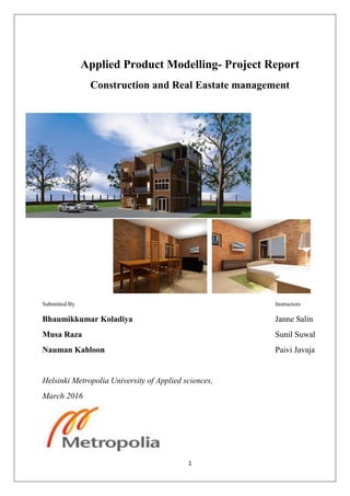
- 1. 1 Applied Product Modelling- Project Report Construction and Real Eastate management Submitted By Instructors Bhaumikkumar Koladiya Janne Salin Musa Raza Sunil Suwal Nauman Kahloon Paivi Javaja Helsinki Metropolia University of Applied sciences, March 2016
- 2. 2 Contents 1. Introduction: ..................................................................................................................................................... 4 Project location Description & Aim....................................................................................................................... 4 2. Project Work-Flow ............................................................................................................................................ 5 3. Archicad Modelling and utilization ................................................................................................................... 6 4.Tekla Structural Designing and utilization ............................................................................................................. 7 4D Scheduling ....................................................................................................................................................... 8 5. Solibri Model Checker and utilization................................................................................................................ 10 6. Discussion and Results ....................................................................................................................................... 11 Archicad .............................................................................................................................................................. 11 Tekla Structures: ................................................................................................................................................. 12 Solibri Model Checker (SMC): ............................................................................................................................. 12 7. Feedback............................................................................................................................................................. 13 8. Attachments........................................................................................................................................................ 13
- 3. 3 List of figures Figure 1 Column grids ............................................................................................................................................... 6 Figure 2 walls from column grids.............................................................................................................................. 6 Figure 3 Model from Archicad and rendering........................................................................................................... 6 Figure 4 view from plane, ......................................................................................................................................... 7 Figure 5 Modelling with grids ................................................................................................................................... 7 Figure 6 Modelling using grids,................................................................................................................................. 7 Figure 7 Modelling using grid lines ........................................................................................................................... 7 Figure 8 column section............................................................................................................................................ 7 Figure 9 Reinforcement details,................................................................................................................................ 7 Figure 10 combined model, ...................................................................................................................................... 7 Figure 11 Column unit............................................................................................................................................... 7 Figure 12 Different origins ........................................................................................................................................ 7 Figure 13 Activities and duration for scheduling...................................................................................................... 8 Figure 14 Review at zero time ,works to be done .................................................................................................... 9 Figure 15 After 7 days, work done and planned....................................................................................................... 9 Figure 16: In this clash we found out that the columns and curtain wall does not have enough space in between. This was communicated to the architect for modification..................................................................................... 10 Figure 17:In this error the wall was extended to such an extent that it was colliding with the column. The wall should end at the face of the column in order to avoid this error. Which was further communicated for revision. ................................................................................................................................................................................ 10 Figure 18: This error was encountered in intersection rule set and there was an intersection between the architectural wall and structural column. The column was merged into the wall which was communicated to structural engineer and architect. .......................................................................................................................... 11 Figure 19 Information take off from solibri ............................................................................................................ 14 Figure 20 Slab area calculation ............................................................................................................................... 14 Figure 22 Concrete quantity from Tekla................................................................................................................. 15 Figure 23 Finish quantity from Archicad................................................................................................................. 15 Figure 24 Opening schedule from Archicad............................................................................................................ 15 Figure 25 Energy evaluation from Archicad............................................................................................................ 16 Figure 26 Intersection report from Solibri.............................................................................................................. 17 Figure 27 Carbon footprint calcuation sample from Solibri ................................................................................... 17 Figure 28 Plan generated from archicad................................................................................................................. 17
- 4. 4 1. Introduction: Construction industry is being revolutionized. Today the technologies of both manufacturing and construction have changed, but not nearly to the same degree. Part of the reason for the different degrees of change can be found in the basic differences between manufacturing and construction. Construction is essentially the process of moving and assembling materials and equipment into a completed, operational facility. Over the past 10 years the impacts of technology on the construction sector have varied by the type of construction being performed, but in general, the changes have been largely evolutionary. Computer-aided design, or CAD, is now a fact of life in the design-construction process. The benefits to the construction industry already have been significant in several respects. These include reduced interferences, time saving, effective communication and virtual models. As technology is taking over the world which results in reduction of human effort, time consumption and conventional manual methods are being obsoleted. Building information Modelling (BIM) is an intelligence based model which provides insight into design, construction, planning, communication in construction of buildings and different projects. BIM has a lot of different tools and applications for various purposes .Tekla Structures and Archicad were used in this report to model architecture and structural design of a 3 Story residential building. Furthermore after completion of design works Solibri model checker was used to check integrity of building in both the designs. Development of an error free model with consolidation of BIM Applications was the main objective. The modelled project is based on the development of a 3-Story residential complex situated at Surat silent zone opposite Surat Airport Gujrat India. The proposed project is based on the ideologies of design and structural elements through experiences and studies. The idea of this project is to design, check and resolve the entire project with the help of Archicad, Tekla and Solibri. The objective is to achieve a model which is error free with the amalgamation of the BIM applications. The project is considered as a live project which has to be built in a specific time frame. Keeping all the possible site analysis and considering a site open from all side we evolved a conceptual design. The project is designed initially as a conceptual model through sketches and then transferred to the BIM applications softwares. Archicad deals with the basic design and development with finalizing the important aspects of project through material specification, design elements and projects details. The final visualization is developed in Archicad after surpassing it through the Tekla structures and finding the errors in Solibri. One of the important aspects of this project is to extract the quality assurance and developing the structure components through Tekla for better understanding of the BIM usability and practical applications. The major transition is done within these three BIM softwares. Scheduling quantity takes off and drawing publishing was done using these three softwares. Project location Description & Aim Project is based in Gujrat, India. The project is a triple story residential complex in line with the local needs and living standards which includes 9 Bedrooms, 3 Living rooms, Toilets, 3 Kitchens, Community Space/ Recreational Area, Balcony/Veranda, 3 Family Living/Prayer Room, Terraces, Corridor, Porch etc., building elements. The residential complex has been designed for the team members to understand the BIM applications and implementations in real time scenario.
- 5. 5 2. Project Work-Flow Step 1 • Basic plan from AutoCAD Step 2 • ArchiCAD Modelling Step 3 • Tekla Structure Modelling Step 4 • Extracting IFC`s from Archicad & Tekla. Step 5 • Solibri Model Checking Step 6 • Quality Assurance Step 7 • Communication & Presentation Step 8 • Quantity Takeoff Step9 • Cost Calculation Step 10 • Energy Simulation and CO2 footprint Step 11 • Project Report
- 6. 6 3. Archicad Modelling and utilization The plan drawings of proposed residential complex were first developed from AutoCAD. Details and elevations were used based on assumptions to make building aesthetically as per local criterion. Further to that the AutoCAD drawings were imported into Archicad for using as trace reference. Building consists of 3 stories with conventional provisions of local usability. Model was started building by defining the composite walls, (different sized walls were used). On completion of walls slabs were provided and walls were extended to the next floor. Columns were provided as per Archicad drawings at defined locations throughout the building. Upon completion of walls and slabs the doors and windows were introduced into the model. The main structure included some balconies and modelling the desired balconies style was found to be little tricky in start but after in depth exploration of the tools, job was completed well. On completion of basic modelling of the structure the materials were changed. On the top floor curtain wall tool was used to build the recreational room. Mesh tool was used for landscaping and asphalt road entrance construction in the residential complex. Landscaping work and object placements for interior (furniture) and exterior design was done selecting different objects. Layers were defined separately for ease at model checking in Solibri and Tekla design. Zoning was done for whole model using zone tool. During energy calculations we experienced an error for central heating i.e. central heating area to be more than zero. Upon updating the zones and redefining the thermal blocks the issue was fixed but the error still stood to be a question for the team. Rendering was done using different environments available in Archicad, light combinations were defined to obtain the best rendered photos of the designed project. Rendering was done for interior and exterior views. We experienced that few times rendering was not progressing even after hours. Doors and windows schedule, energy evaluation report, 3D drawings, finished materials inventory and drawing layout in pdf format was exported from Archicad on completion of final modelling. During using Archicad so many tools were explored and a very good understanding and functioning of Archicad was established. Figure 1 Column grids Figure 2 walls from column grids Figure 3 Model from Archicad and rendering
- 7. 7 4.Tekla Structural Designing and utilization Structural detailing was done by using tekla structure software version 21.Structural elements such as pad footings, columns, beams and slabs were drawn by using tekla. Material used for these elements was concrete according to the project requirements. After drawing all elements, Reinforcement was provided in all concrete components which were done by going to search catalogue in tekla structures and finding suitable reinforcements for each group of elements separately. For example for beams reinforcement, the suitable reinforcement was to be found in search catalogue under number 63. Once this was chosen, there were options to choose modification and changes in required reinforcement. All dimensions for all structural elements were assumed after group discussion. Finalized sizes of all elements were: Column: 254×254mm(10”x 10”) Beams: 457×254mm(1‟6” x 10”) Slabs: 127mm (thickness 5”) Foundations: 1524×1524mm(5‟ x 5 „x 2 „ depth) and at depth of 7 ft from 0.0 level For structural detailing in Tekla two approaches were applied. First grids were set up and reference was taken as same it was in Archicad. Heights and spacing of grids were defined from the Archicad as well. Figure 4 view from plane, Figure 5 Modelling with grids, Figure 6 Modelling using grids, Figure 7 Modelling using grid lines Figure 8 column section, Figure 9 Reinforcement details, Figure 10 combined model, Figure 11 Column unit, Figure 12 Different origins After finishing the modelling, when IFC file of Archicad was imported into tekla, it was found that the origins of both Archicad reference model and tekla were not same. When adding the reference model of Archicad into tekla, the origin of that reference model moved to origin of the tekla model.
- 8. 8 There were some columns were founded not in alignment as they were in Archicad after solving the origin issue. They were just offset from where they should be. The defining of grids was founded faulty this time. Many approaches and different techniques were tried to solve this issues such as moving tekla columns to reference column in Archicad, Arranging grids and to move the whole reference of grid lines of Tekla model. But this issue could not solve. At last, after investigating it thoroughly, the group came to conclusion this can be due to change of unit system in both software. The units in Tekla were in mm while this was converted from feet from Archicad. So this could be the possible reason that when IFC file from Archicad imported into Tekla, some of the measurement could be missing. After group discussion it was decided to design the model again. This time IFC file from Archicad was taken as reference and all Columns, Beams and Slabs were traced and drawn from that reference model of Archicad. After finishing the model, only 3d view of that model could be seen. We developed different views by choosing view by plane and by defining floor to floor height of each story. In order to avoid overlapping quantities of Columns with slab, Hollow Core Slab Cut Part (92) were provided which cuts column through slab. Finally, general arrangement drawing of the 3D view and one cast in unit drawing was created. After completing the model in tekla, a basic schedule plan was made by using tekla task manager manually. All start date and end date of each activity were assigned in each task which resulted in the gant chart for scheduling. 4D Scheduling Tekla task manager were used for scheduling the whole work flow. In order to divide the whole column into different floors, splitting tool was used. By using that tool, it didn‟t just splitted the column but the inside reinforcement inside it as well. Figure 13 Activities and duration for scheduling To have 4d visualization, project status visualization tool has been used. Before using it first grouping were done in object representation according to the rules which were founded in Tekla assistance guide. There were four object groups created and different colour for each group had been assigned. After object representation, dates were set up in project status visualization menu bar and number of days for review date was also introduced.
- 9. 9 Figure 14 Review at zero time ,works to be done As it can be seen from the picture above that the review date is same as the start of project date so the whole structure looked blue which is representing that the project has not started yet until that date. By pressing step backward or forward button the progress of the whole project can be visibly seen and it can easily estimated that how much work has finished and how much still left until the defined date. This really helps to see how project going and if there will be any kind of delay in future or if there will be any future issue upcoming, it can be handled before time which save time and money. By using it, project communication can be very simple, easy and understandable to all workers. The progress of work can also be very easily reviewed and can be seen from it. Figure 15 After 7 days, work done and planned
- 10. 10 This picture showed the review date and how many task have been completed, started and to be started till that time. This can also give good time to be prepared for the next task and its starting time. 5. Solibri Model Checker and utilization Solibri model checker was used to check the integrity and clash detection among the architectural and structural models. By using the checking tools it was understood whether the created model has any missing, misplaced component or any overlapped elements in the model. Also, allowing to be certain that the components are modelled within realistic and reasonable limits. For example the doors and windows are of suitable size and placed correctly or the slab dimensions are modelled to the correct thickness. After running the tool a few clashes appeared, some of them were minor and some of them were potential issues. Archicad model and tekla model were exported as IFC models and then imported into the Solibri Model Checker for checking. After combining both the models into Solibri model checking was done and following rule sets were applied. 1. Intersection Checking for architectural elements 2. Clearance check 3. Intersection Checking between architectural and structural elements Type or errors found are discussed below Figure 16: In this clash we found out that the columns and curtain wall does not have enough space in between. This was communicated to the architect for modification. Figure 17:In this error the wall was extended to such an extent that it was colliding with the column. The wall should end at the face of the column in order to avoid this error. Which was further communicated for revision. Wall should end at column face. No space between column and curtain wall.
- 11. 11 Figure 18: This error was encountered in intersection rule set and there was an intersection between the architectural wall and structural column. The column was merged into the wall which was communicated to structural engineer and architect. After analysis of the results obtained from Solibri model checker the critical errors/issues were communicated/report using the communication tool. Presentation was generated for the errors using the same communication tool in the Solibri for detailed discussion among the team members. Furthermore the quantities were taken off using Solibri quantity take off tool for further cost estimation. 6. Discussion and Results Archicad Archicad is an efficient, productive, reliable and a very professional tool for modelling and construction management industry‟s professional. Considering this as our first project we had to experience quite a lot of issues in the start, which we were able to fix most of them by searching, reading on Internet and discussion among the team members. We were able to develop a very good communication among us and understood how Archicad can help us improving the design, construction and post construction activities in real time projects. Following are our findings about the Archicad for modelling, Archicad is not so difficult to learn but needs considerable time investment to explore all the tools in details and software has a lot to offer than the modelling. File organization is a great feature of Archicad. Layers combination setup is great and extensive which allows much ease and understanding during work. Getting worried about 2D standard is not something to get worried about; one can create its own line types. (True weight display of Archicad make is easier and easily understandable in comparison to the Autocad ‟s coloured weights.) Drawing in 2D using Archicad is much faster and intuitive than AutoCAD. Using objects from Library is very easy with complete details and modification options are also available. Some extensions are never properly updated as we noticed in the case of Stair making. Archicad runs on OSX & very good visual user interface it was easy to remember the interface due to visuals. Structural column intersecting with wall.
- 12. 12 Tekla Structures: There were many restrictions founded in using all tools up to full extent, as educational version of tekla structure were provided in which many commands had some restriction. For example, load analysis were not possible and allowed to do with tekla education version, as it was not giving allowance to export load combination to other analysing software. Advantages: By having virtual view of reinforcement in 3d model the chances of mistakes in reinforcement cutting can be minimised which in result would save money and time for the user. The very detailed as-built models enable the highest level of constructability and production control. Centralizing data into the model allows for more collaborative and integrated project management and delivery that translates into increased productivity and elimination of wastage. Gives freedom to structural designer and they can use and try different combinations very quickly. Exchanging files and importing and exporting data is very easy and simple. Solibri Model Checker (SMC): Solibri is a very effective tool for clash detection, communication and information takeoff from IFC model. We can define categories and sub categories and displays it by element type location and material. It uses Rulesets to check the clashes ,there are some predefined rulesets and one can also make their own ruleset based on project requirements. We can use the rulesets for Clash Detection, Quality Assurance, Model Craft, Missing Parameters, Naming Conventions, Building Logistics, Code Compliance, and even Validation of Design Ideas. Slides created from Solibri has properties of its own as it can track Decisions, Comments, Locations, Date slide created, Status, and Responsibilities. These can be added to presentation and repoted to respective department by pdf or xls format. Though, there are some limitations with Solibri like, Inability to add slides to an existing presentation. Inability to add the “newest” created slides to a new presentation. Inability to have a user categorization of results. It can not group information take off details which results in long files. SMC can be used for following purposes, Building owners evaluating proposed design alternatives Building owners and facility managers checking design proposals against BIM guidelines, program requirements, cost and energy budgets, and security requirements Architects checking model integrity and completeness before sending designs to their clients Structural engineers checking their design for consistency with architect‟s design MEP engineers looking to optimize duct routing and avoid clashes with other elements
- 13. 13 Design teams cross-checking their designs by merging models into one environment Construction companies checking that building models have valid and sufficient data to support cost estimating, scheduling and project planning Facility managers evaluating material life-cycle costs and maintainability 7. Feedback We consider this course to be very useful for our future endeavours and knowledge regarding BIM. We had chance to understand and use Archicad, Tekla Structures, Solibri Model Checker & Tekla BIM sight for this project. There were many problems encountered while working on the project and some of them were fixed by exploring more information, Internet search, and brainstorming as well as team discussions. Some of the errors and problems are still question for us, which we intend to resolve with discussion with course instructors and self-sresearch. We consider this project and course to be a very useful medium for us to understand the applications and use of BIM based software’s in real time construction. We would like to thank our course instructors for their best possible guidance and support. Time was a real constraint for this course and we feel we could have learned more tools if more time invested, but this brings up the motivation to explore more and learn more to improve our BIM knowledge. One suggestion we would like to propose is to arrange one lecture after completion and presentations of the project work so the issues which were encountered and we were not able to resolve alone, they could be resolved under course instructor’s guidance. 8. Attachments Cost estimation Cost is one of the key components to ensure a smooth output and on time delivery of the project. Quantities were taken off using Tekla organizer tool and Solibri Model checker for further cost evaluation. Rates were used in cost estimation as per the current local market prices for each material. The cost was calculated based on the limited information available however labour cost, engineering cost, MEP, Procurement were not included due to unavailability of required data, material specification and local market prices. *Quantity of the cement sand For 1:6 cement sand mortar the local price is 3000INR considering 250Rs price of one bag and 900Rs per cum of sand. Item Description Quantity Rate (INR) Amount (INR) Concrete 159CUM 5200/cum 826800 Steel Reinforcement 5933KG 43/kg 232157 Bricks 448CUM 4200/cum 1881600 Cement/Sand Mortar 134CUM 3000/cum 40200 Concrete Block Structural 90SQM 1500/sqm 135000 Total 3115757
- 14. 14 Figure 19 Information take off from solibri Figure 20 Steel calculation from Tekla
- 15. 15 Figure 21 Concrete quantity from Tekla Figure 22 Finish quantity from Archicad Figure 23 Opening schedule from Archicad
- 16. 16 Figure 24 Energy evaluation from Archicad
- 17. 17 Figure 25 Intersection report from Solibri Figure 26 Carbon footprint calcuation sample from Solibri Figure 27 Plan generated from archicad