Part modules help(nx10)_12345678
•
0 likes•158 views

NX10 Help-documentation; Using "Part module"

Recommended
Recommended
More Related Content
What's hot
Similar to Part modules help(nx10)_12345678
Similar to Part modules help(nx10)_12345678 (20)
Recently uploaded
Recently uploaded (20)
Part modules help(nx10)_12345678
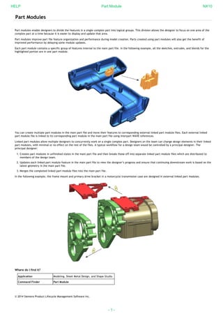
- 1. Part Modules Part modules enable designers to divide the features in a single complex part into logical groups. This division allows the designer to focus on one area of the complex part at a time because it is easier to display and update that area. Part modules improve part file feature organization and performance during model creation. Parts created using part modules will also get the benefit of improved performance by delaying some module updates. Each part module contains a specific group of features internal to the main part file. In the following example, all the sketches, extrudes, and blends for the highlighted portion are in one part module. You can create multiple part modules in the main part file and move their features to corresponding external linked part module files. Each external linked part module file is linked to its corresponding part module in the main part file using interpart WAVE references. Linked part modules allow multiple designers to concurrently work on a single complex part. Designers on the team can change design elements in their linked part modules, with minimal or no effect on the rest of the files. A typical workflow for a design team would be controlled by a principal designer. The principal designer: Creates part modules in unfinished states in the main part file and then breaks these off into separate linked part module files which are distributed to members of the design team. 1. Updates each linked part module feature in the main part file to view the designer’s progress and ensure that continuing downstream work is based on the2. latest geometry in the main part file. Merges the completed linked part module files into the main part file.3. In the following example, the frame mount and primary drive bracket in a motorcycle transmission case are designed in external linked part modules. Where do I find it? Application Modeling, Sheet Metal Design, and Shape Studio Command Finder Part Module © 2014 Siemens Product Lifecycle Management Software Inc. HELP Part Module NX10 - 1 -
- 2. Part Modules in the Part Navigator Part modules appear in the Part Navigator as features with sub-features. When you first create a part module, it becomes active and does not contain any sub-features. As you start to create features, they appear under the part module feature. Explicit inputs and outputs You can explicitly create inputs and outputs using the Define Part Module Input and Define Part Module Output commands. Inputs are extractions of the geometry objects and expressions that you select from the part. It is what isolates the part module from the upstream part. These objects are the parent references for the features that you create later. Outputs are extractions of those features and expressions you specify from the part module. Downstream features of the main part file are based on the output features. It is what isolates the part module from the downstream part. When a part module is inactive, the output objects are the objects displayed and the other objects are hidden. Implicit inputs and outputs When a part module is: Active, NX can automatically create inputs when you select objects outside the part module. Inactive, NX can automatically create outputs when you select objects inside the part module. Caution If you plan to convert an internal part module to an external part module, you must explicitly define your inputs and outputs. You will not be able to convert feature groups if NX implicitly defines the inputs and outputs. © 2014 Siemens Product Lifecycle Management Software Inc. HELP Part Module NX10 - 2 -
- 3. Internal and external part modules A part module exists either as an internal part module solely within the main part file, or as an external linked part module that links the part module in the main part file to a corresponding part module in another part file using interpart WAVE references. Internal part module External linked part module When you convert an internal part module to an external linked part module file, NX: Creates WAVE links from the input objects in the main part file to the input objects in the linked part module file. Moves the part module features to the linked part module file. Creates WAVE links from the output objects in the linked part module file to the output objects in the main part file. Preserves associativity between the main part file and the linked part module file. Use the Create Linked Part Module Part to create a linked part module in a separate part file. Where do I find it? Application Modeling, Sheet Metal Design, Shape Studio Command Finder Create Linked Part Module Part © 2014 Siemens Product Lifecycle Management Software Inc. HELP Part Module NX10 - 3 -
- 4. Distributing work areas using part modules workflow Linked part modules allow multiple designers to work on a single complex part at the same time without using Assemblies functionality. You can assign specific work areas in a part file to individual designers using the Create Linked Part Module Part command. This process establishes ownership of segments of a complex part to separate designers. The lead designer: Determines where to divide the main part file into separate work areas.a. Creates linked part modules for each area.b. 1. The individual designers: Create new features and expressions in their linked part module file.a. Keep inputs from the main part file updated the linked part module file as needed.b. Specifies output geometry to be used in the main part file.c. 2. The lead designer: Updates progress from the linked part module file in the main part file as needed.a. Continues design work in the main part file.b. 3. Linked part module relationships You may want to break the associativity between the main part file and a linked part module file and establish the associativity to a different linked part module file. This functionality is useful in cases where you create multiple designs for a single area of a complex part and need to update the part depending on the chosen design. You must first break the associativity by using the Break Part Module Relationship command, and then establish the new associativity by using the Establish Part Module Relationship command. Breaking a linked part module relationship The Break Part Module Relationship command breaks the relationship between the file that is active when you select the command and the file to which it is WAVE linked. When you select the Break Part Module Relationship command from the main part file, the Output WAVE links are broken and the linked part module is no longer up to date. When you select the Break Part Module Relationship command from the linked part module file, the Input WAVE links objects are broken. HELP Part Module NX10 - 4 -
- 5. If the main part file has just one linked part module, NX breaks the relationship immediately. If there are two or more linked part modules in the main part file, you must select the relationship that you want to break in the Select Part Module dialog box. Establishing a part module relationship Use the Establish Part Module Relationship command to establish associativity between the main part file and a linked part module file that is loaded in the same session. Where do I find it? Application Modeling, Sheet Metal Design, and Shape Studio Command Finder Break Part Module Relationship or Establish Part Module Relationship © 2014 Siemens Product Lifecycle Management Software Inc. HELP Part Module NX10 - 5 -
- 6. Merge Part Module A principal designer uses the Merge Part Module command to merge completed linked part module files back into the main part file. Merges the corresponding linked part module that is in a separate part, into the part module in the main part. The main part will no longer have WAVE link dependencies to the linked part module in the separate part. Where do I find it? Application Modeling, Sheet Metal Design, and Shape Studio Command Finder Merge Module Update inputs and outputs You can use the: Update Input References command to update the links that comprise the inputs of the linked part module part file. Update Output References command to update the links that comprise the outputs of the linked part module part file in the main part. Where do I find it? Update Input References Update Output References Modeling, Sheet Metal Design, and Shape Studio HELP Part Module NX10 - 6 -
- 7. Controlling part module updates You can control how NX updates your internal part modules, and prevent part modules from updating automatically. Use the Delay Part Module Update and Update Part Modules commands to update one feature at a time or update an entire part module. To update features, leave Delay Part Module Update turned on, and control feature update using the out-of-date icon in the Part Navigator. When you click the out-of-date icon for a feature, NX updates that feature and any out-of-date parents. When you click the out-of-date icon for a part module, NX updates that part module, all its member features, and any out of date parents. To update all part modules you can: Click Update Part Modules . Turn off Delay Part Module Update . Because you can prevent NX from updating part modules automatically, you can postpone updates of large portions of a part to a time when it is more convenient. You can also eliminate interim updates when they are not necessary. Part Navigator Updates In the Part Navigator the Up to Date column displays the following icons: Up to date Out of date Failed to update Note NX does not update if you click . Expressions dialog box updates The Expressions dialog box now has the same Up to Date column as the Part Navigator. You can use the Active Part Modules Only check box in the Expressions dialog to display only the expressions used in an active part module. Where do I find it? Application Modeling, Sheet Metal Design, Shape Studio Command Finder Delay Part Module Update or Update Part Modules © 2014 Siemens Product Lifecycle Management Software Inc. HELP Part Module NX10 - 7 -
- 8. Define Part Module Input dialog box Input Object Type list Lets you filter the types of input objects. Select Object Lets you select objects to be extracted and used for input references. Name list Lists the input objects selected. Add New Object Lets you create multiple extracted objects. Remove Lets you delete individual objects from the list. Expressions This option is available when the Expression Object Type is selected. Expression references that are needed to support the selected geometric references are extracted from the part. Filter list Lets you select any expressions that are required for the geometric references. Name list Lists the expression sets you have specified for the extracted inputs. Remove Lets you delete individual expression sets from the list. Shared Body Define Shared Body Input check box Multiple designers can modify different objects on the same body at the same time even if the body is not divided into partitions. To enable this workflow the lead designer must use this option to create multiple part modules that contain the same input body. Designers can add features only to the edges and faces of their particular shared body part module. The elapsed time it takes to blend an automotive body panel or engine block can be significantly reduced if multiple designers can simultaneously blend different portions of the same part at the same time. Printers and copiers can have complex sheet metal parts that can also benefit from dividing the modeling of sheet metal features among multiple designers. In the past release, a body had to be physically split up into separate bodies to divide the work. Modified Geometry list This option is available when the Define Shared Body Input check box is selected. Lets you select the Whole Body or Selected faces. © 2014 Siemens Product Lifecycle Management Software Inc. HELP Part Module NX10 - 8 -
- 9. Define Part Module Output dialog box Note This command is available only for a non-linked part module or from the separate link part file of a linked part module. Output Object Type list Lets you filter the types of output objects. Select Object Lets you select objects to be extracted and used for output references. Name list Lists the output objects selected. Add New Object Lets you create multiple extracted objects. Remove Lets you delete individual objects from the list. Expressions This option is available when the Expression Object Type is selected. Expression references that are needed to support the selected geometric references are extracted from the part. Filter list Lets you select any expressions that are required for the geometric references. Name list Lists the expression sets you have specified for the extracted outputs. Remove Lets you delete individual expression sets from the list. © 2014 Siemens Product Lifecycle Management Software Inc. HELP Part Module NX10 - 9 -
- 10. Part Module Relationship dialog box Select Part Module Select Part Module Feature Lets you select an existing part module in the work part from the Available Part Modules in Work Part list. Old Relationship Information Displays the existing link relationship data of the main design file to its linked part file. Part Module Relationship Status: Up to Date or Broken Main Part File: Lists the name and output status of the main design file. Output Links: Lists the number of geometric and expression output links. Outputs Links Status: Lists the status of the output links, either Up to Date, Pending, or Broken Part Module File: Lists the name and input status of the linked part file. Inputs Links: Lists the number of geometric and expression input links. Inputs Links Status: Lists the status of the input links, either Up to Date, Pending, or Broken. Select Linked Part Module Lets you select a linked part module in the main design file that is selected in the Available Part Modules in Work Part list. When you make a selection from the list, the name of its linked part module and its linked part file name appear here. Part Module Lists the names of valid link part modules in the part file, from which you can choose. Loaded Part Lists the loaded part file names of the listed link part modules. New Relationship Information The information presented in this window is the same as that of the Old Relationship Information, except that it is for the projected new link relationship data. © 2014 Siemens Product Lifecycle Management Software Inc. HELP Part Module NX10 - 10 -