3. N
N
F
DC
ae
ap
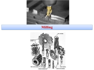
A milling cutting tool is similar to the
turning cutting tool, but many tools called
“teeth” integrate it.
INTRODUCTION-Milling
•The tool is spinning.
•One or more linear movements
may have the tool or the part.
N Spindle speed (rpm)
Vc Cutting speed (m/min)
Dc Tool diameter (mm)
F Feed rate (mm/min)
ap Axial cutting depth (mm)
ae Radial cutting depth (mm)
5. Face Milling
Shoulder Milling
(Face & Side Milling)
Side or Peripheral
Milling
• Cutting depth in axial
direction.
• It uses mainly the cutting edges
on on the periphery of the tool.
• Surface roughness created by
face teeth.
•Cutting depth in axial and
radial direction.
• It uses the cutting edges on the
face and periphery of the tool.
•Surface roughness created by
face and side teeth.
• Cutting depth in radial
direction.
• It uses mainly the cutting edges
on the periphery of the tool.
• Surface roughness created by
side teeth.
INTRODUCTION: MILLING TYPES
Cutting mov.
Feed mov.
Cutting mov.
Feed mov.
Cutting mov.
Feed mov.
6. INTRODUCTION: MILLING TYPES
Up milling Or conventional Down milling or Climb Milling
1. Work piece is fed in opposite direction of
that of cutter.
2. Chips are progressively thicker.
3. Strong clamping is required since the
cutting force is directed upwards and tends
to lift the work piece.
4. Poor surface finish and used for hard
materials.
1. Work piece is fed in same direction of
that of cutter.
2. Chips are progressively thinner.
3. Strong clamping is not required since the
cutting force is directed downwards and
keeps work piece pressed to table.
4. Good surface finish and used for soft
materials.
8. Horizontal and Vertical Milling machines
MACHINE TYPES
Rotational axis
direction
Rotational axis
direction
Horizontal Milling MachineVertical Milling Machine
According to their main rotational axis…
11. • Manual movements execution.
• Manual tool and part change.
• Machine may have or not an overarm: Spindle mounted to a movable
housing on the column to permit positioning the milling cutter forward or
rearward in a horizontal plane.
Machine principal components:
1. Column: supports the spindle. The tool has no linear movements,
just the rotational cutting movement.
2. Knee: supports the work table. It has all the linear movements: X, Y
& Z.
Machine types:
1. VERTICAL MACHINE
2. HORIZONTAL MACHINE
3. UNIVERSAL MACHINE
MACHINE TYPES
Z
X
Y
Conventional milling machines
Column and knee type
VIDEO
12. • Cutter is directly mounted in the spindle.
• Typical for face and end milling operations.
• Arbor supports the cutter and an overarm
the arbor.
• Typical for side or peripheral milling
operations.
1 2
Column and knee type
MACHINE TYPES
VERTICAL MILLING MACHINE HORIZONTAL MILLING MACHINE
Conventional milling machines
13. • It is a vertical and horizontal milling machine at the same time.
• Types:
MACHINE TYPES
Column and knee type
UNIVERSAL MILLING MACHINE
3
Vertical & horizontal
spindle
Hure spindle:
It has a swiveling spindle that allows to swivel the
spindle at different angles. Vertical milling
attachment
VIDEOVIDEO
Conventional milling machines
14. The tool has the perpendicular movement.
The worktable has the X & Y movements.
Greater rigidity. Used for voluminous and
heavy parts.
A special machine type:
» It has a roughing spindle and a
finishing spindle.
Bed type
Z
MACHINE TYPES
ROTARY TABLE TYPE
Z
Conventional milling machines
15. Automatic movements execution.
Manual tool change.
Manual part change.
Usually, it is not needed any special workholding
device.
• Machining time: less than in an universal milling.
• Idle time: very short
• Set-up time: slightly important (programming)
• Series: 10 to 1000 parts, or more.
• Precision: IT7/8, Ra ~ 0.8 -1.6 µm.
MACHINE TYPES
CNC Milling machine
CNC Machines
16. The part has the longitudinal axis movement.
Spindle carriers are mounted on cross-rails (bridge structure).
Large size milling machines.
Suitable for flat surfaces of heavy components.
May use several spindle heads (vertical or horizontal).
Bed type
1 BRIDGE TYPE OR PLANER MILLING MACHINE
Y
X
Z
VIDEO
MACHINE TYPES
CNC Machines
17. Similar to the bridge type machine, but
the workpiece has no movement at all.
Typically used for large size parts.
TRAVELLING COLUMN MILLING MACHINE
The part has no movement at all.
Bed type
2 3GANTRY MILLING MACHINE
Y
Y
Z
X
X
Z
VIDEO VIDEO
MACHINE TYPES
CNC Machines
18. It is a CNC milling machine equipped by an
automatic tool changer.
Automatic tool changer using tool magazine or
carousel.
Automatic part changer using pallets (optional).
MACHINE TYPES
Machining Centre
tool magazine tool carousel
tool magazine CNC
Machining time: similar to CNC Milling machines.
Idle time: smaller than in CNC Milling machines.
Set-up time: slightly important (programming
setting-up)
&
Series: 10 to 1000 parts, or more
Precision: IT7/8, Ra ~ 0.8 -1.6 µm.
CNC Machines
19. MACHINE TYPES
Machining Centre
3 AXIS
Machine has CNC controlled
X,Y & Z linear movements.
4 AXIS
Machine has CNC controlled X,Y & Z linear movements
+ 1 rotational movement.
a) Horizontal rotary table
b) Vertical rotary table
c) Rotary spindle
To obtain surfaces with a cylindrical pattern (e.g. gears,
polygonal geometries,…).
Integrated vertical rotary table
(C axis)
VIDEO VIDEO Horizontal rotary table (A axis)
19
CNC Machines
20. MACHINE TYPES
Trunnion table
Vertical machine Horizontal machine
Combination type
Higher versatility (part can be clamped
Swiveling head
Heavier parts can be machined.
Shorter tools are needed.
A larger working volume.
More powerful spindle Heavier removal
rates.
1
2
3
Machining Centre
5 AXIS
Machine has CNC controlled X,Y & Z linear movements
+ 2 rotational movements.
Types:
VIDEO
VIDEO
on the rotary table or out of it).Bigger rotational movement capability.
CNC Machines
21. • Several technologies are integrated into one machine:
turning, milling, drilling,…
• It has evolved from turning machines.
• The heart of the machine is the tool spindle (B
spindle), which even can be tilted. It provides milling,
drilling and tapping capability along with turning,
facing, grooving and threading.
• This spindle is serviced by an automatic tool changer
that resides outside the cutting zone.
• It may have a double spindle and one/two tool turrets.
• Application: very complex parts.
VIDEO
MACHINE TYPES
Machining Centre
MULTITASKING MACHINE – HORIZONTAL (I)
CNC Machines
23. Vise
The most common type of workholding
device for small parts.
Part is hold by pressure driven:
Mechanically
Pneumatically
Hydraulically
Types based on the degree of freedom:
Plain vise
Plain vise with swivel base
Universal vise with swivel base
Plain vise Plain vise with swivel base Universal vise
WORKHOLDING DEVICES
MECHANICAL VISE VIDEO
PNEUMATIC VISE HYDRAULIC VISE
24. Clamps
Used for big size or irregular parts.
Part is hold using clamps, t-slot bolts, screws, washers, nuts, parallels, step blocks,…
It is important to keep in mind the efforts/deformations produced on the part.
WORKHOLDING DEVICES
Step block
Angle plate
Toe mold clamp
Cam clamp
Washer
C clamp V blockSwing clamp
T-nut
T-slot bolt
VIDEO
25. Modular fixturing system
Based on a drilled and/or grooved baseplate.
It allows to build different workholding systems from a set of standard
components (clamps, positioners,…).
WORKHOLDING DEVICES
VIDEOVIDEO
26. Indexing head / Rotary table
MOTOR DRIVEN
Commonly used for machining angularly equidistant surfaces.
The chuck allows to hold and rotate the part working at different
angles.
Similar clamping possibilities to the turning process:
Jaw chuck
Between chuck and center
Between centers
VIDEO
MANUALLY OPERATED
WORKHOLDING DEVICES
VIDEO
27. Magnetic Chuck
Ideal for ferromagnetic parts.
Powerful workholding system.
Usually electronically activated.
Part centering may be time consuming.
WORKHOLDING DEVICES
VIDEO
28. Vacuum Chuck
Ideal for thin and flat metal sheets, non-porous surfaces.
Hold down forces are not extremely high.
Uniform holding pressure on the entire workpiece surface.
WORKHOLDING DEVICES
VIDEO
34. MACHINING OPERATIONS
1.Face Milling
High feed
Low cutting depth
Face Milling:
Operation carried out for producing a flat
surface, which is perpendicular to the axis
of rotating cutter.
Cutter: Face milling cutter.
Machine: Vertical Milling Machine
36. END MILLING
MACHINING OPERATIONS
3. Slot Milling
1
Slot Milling:
Operation of producing slots like T-slots, plain slots etc.,
Cutter:
End milling cutter, T-slot cutter, side milling
cutter Machine:
Vertical Milling Machine
37. MACHINING OPERATIONS
5. Helical Slot Milling
It requires a previous slot milling operation of width
bigger than the T-shape tool shank.
The use of air flow is highly recommended in order
to evacuate the chip continuously.
4. T-shape Slot Milling
It requires a coordination between the rotational
speed (N) and the feed per revolution (fn).
38. MACHINING OPERATIONS
6. Dovetail Milling 7. Form Milling
VIDEO VIDO
Form Milling:
Operation of producing all types of angular cuts
like V-notches and grooves, serrations and
angular surfaces.
Cutter: Double angle cutter.
Machine: Horizontal Milling Machine
39. MACHINING OPERATIONS
Two or more milling cutters mounted on the same
arbor.
Displacing the cutters half a pitch in relation to
each other assists in avoiding vibration.
High productivity, high removal rate.
Medium/big series.
The use of a fly-wheel reduces torsional vibrations.
8. Gang Milling
43. A curved surface is milled while rotating
the workpiece around its centre point.
MACHINING OPERATIONS
Used mainly for internal features.
Same principle as for circular milling /
ramping, but with component rotating.
Periphery turn milling – 3/4 axesFace turn milling – 4/5 axes
Main method for external machining.
2 METHODS:
13. Turn Milling
44. VIDEO
MACHINING OPERATIONS
14. Boring
Excellent dimensional
tolerances and surface
roughnesses.
ROUGHING FINISHING
a a a >a
BORE FACE GROOVING
It is a productive alternative way to produce
circular grooves.
Increased productivity.
Diameters from 47mm to 1275mm.
It can be done in vertical or horizontal machines.
46. MACHINING OPERATIONS
16. Thread Milling
TAPPING
1
Synchronization of the feed movement and rotational movement is a must.
If the machine spindle is not prepared for direct threading, a special
toolholder needs to be used.
47. MACHINING OPERATIONS
The reamer never should be
spinned counterclockwise.
Straight flute
Axial coolant supply
For blind holes
Spiral flute
Lateral coolant supply
For through holes
RIGHT WRONG
Objective: To achive a good surface roughness and good
dimensional tolerances (H7) in a pre-drilled hole.
High penetration rates and small depths of cut.
The tool is called “reamer”.
17. Reaming
60. Face milling
It is aimed to machine a steel flat surface using a face milling tool. The surface to be machined is 100
mm wide by 300 mm length.
Determine the cutting time knowing that a finishing operation will be accomplished in a single cutting
depth, the carbide tool diameter has 12 teeth and a Ø = 150 mm. The entry and exit security distance
are 3mm.
For additional cutting data, please refer to “Cutting parameters” section at the end of this presentation.
MACHINING TIME
A slot of 25 mm depth is to be cut through a work piece 200 mm long with the HSS side cutter whose
diameter is 150 mm and has 10 teeth. The cutting speed is 50 m/min and feed is 0.25 mm per tooth.
Find 1.feed rate in mm/min. 2. total cutter travel. 3. Total Machining time .
Peripheral or side milling
61. CUTTING PARAMETERS: MILLING
Other milling: slot milling, t-shape milling, dovetail milling, form milling.
D: Roughing operation
A: Finishing operation
MACHINE
WORKPIECE
MATERIAL
TOOL MATERIAL OPERATION Vc
(m/min)
fz
(mm/tooth*rev)
Ap
(mm)
Ae
(mm)
MILLING
MACHIN
E
STEEL
ALUMINIUM
HIGH
SPEED
STEEL
(HSS)
Face milling D 20 - 25
A 25 - 30
0.05 – 0.1
0.01 – 0.05
D 1-2
A 0.2-0.5
D (~2/3)Ø
A (~2/3)Ø
Side milling D 20 - 25
A 25 - 30
0.05 – 0.1
0.01 – 0.05
D (50%-
80%)Ø A
(50%-80%)Ø
D (10%-25%)Ø
A (5%-10%)Ø
Other milling D 15 - 20
A 20 - 25
0.05 – 0.1
0.01 – 0.05
HARD METAL Face milling D 80 - 100
A 100 – 120
0.05 – 0.1
0.01 – 0.05
D 1-2
A 0.2-0.5
D (~2/3)Ø
A (~2/3)Ø
Side milling D 80 - 100
A 100 – 120
0.05 – 0.1
0.01 – 0.05
D (50%-
80%)Ø A
(50%-80%)Ø
D (10%-25%)Ø
A (5%-10%)Ø
Other milling D 70 - 90
A 90 – 100
0.05 – 0.1
0.01 – 0.05
HIGH SPEED D 50 - 70 0.05 – 0.1 D 1-2 D (~2/3)Ø
A 70 - 90 0.01 – 0.05 A 0.2-0.5 A (~2/3)Ø
Side milling D 50 - 70
A 70 - 90
0.05 – 0.1
0.01 – 0.05
D (50%-
80%)Ø A
(50%-80%)Ø
D (10%-25%)Ø
A (5%-10%)ØSTEEL
(HSS)
Other milling D 40 - 60
A 60 - 70
0.05 – 0.1
0.01 – 0.05
HARD METAL Face milling D120 - 150
A 150 – 180
0.05 – 0.1
0.01 – 0.05
D 1-2
A 0.2-0.5
D (~2/3)Ø
A (~2/3)Ø
Side milling D120 - 150
A 150 – 180
0.05 – 0.1
0.01 – 0.05
D (50%-
80%)Ø A
(50%-80%)Ø
D (10%-25%)Ø
A (5%-10%)Ø
Other milling D100 - 130
A 130 – 150
0.05 – 0.1
0.01 – 0.05