1. FIBERGLASS BOX BEAM: J. Beam Wellington III
Shawn Baker and Tim Carlson
Dept. of Materials Science & Engineering, University of Washington
Bridge #:
S6-3946
PROBLEM STATEMENT
Design a box beam using a combination of
fiberglass plies and resin that will hold a
distributive load of 7,000 lbf applied at the
center.
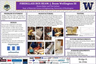
MANUFACTURING
High thread count fiberglass was used in the final iteration to avoid
soaking up unnecessarily large amounts of resin. Most plies were cut
using an automated fabric cutter or by hand (Figure 1). Each ply is
then wetted with resin and assembled in specific directions to
withstand the most applied force (Figure 2 and 3). The top, bottom,
core, and webs are pressed and bound tightly together (Figure 4 and
5). The beam is wrapped in breather and sealed in an air-tight bag to
be cured in the autoclave at 270ᵒ F for 2 hours (Figure 6).
TESTING
The first iteration was made with wide tow fibers that held
over 15000 lbf, but weighed 1432g. The second iteration
was made with more consideration of optimizing weight
while maintaining strength. However, the second beam
failed early at 3429 lbf at 698g because of dry spots at the
supports of the beam that acted as stress concentrators.
The final build maintains this optimized design while
ensuring adequate resin distribution.
DESIGN
There are four components to this beam,
entirely made of fiberglass weave fabric:
• Two C-channels on either side of a center
square section are constructed with plies
mostly oriented at ±45° angles to account for
shear stress.
• Top flange plies oriented in 0° or 0°/90°
directions and consists of more plies than the
bottom flange because of a greater
compressive stress.
• Bottom flange has more plies of fiberglass at
the ends, to withstand more tensile stress.
FUTURE IMPROVEMENTS
• Minimize resin content and pooling between plies to
reduce the weight of the beam.
• All beams tested failed at the ends of the beam. I suggest
to replace more plies on the top and bottom with tabs to
strengthen the ends of the beam while maintaining low
weight.
ACKNOWLEDGEMENTS
• Brian Flinn, Ph. D- UW MSE
• UW SAMPE Officers & Members
• Jeffrey Wollschlager- Altair EngineeringFigure 6: Vacuum bagged beam
Figure 8: Side by side comparison of the first two
iterations.
Figure 1: Cutting unidirectional plies Figure 2: Wet layup process Figure 3: Bottom being assembled
Figure 4: Pressing the core
together with the bottom and
top
Figure 5: All pieces of the beam are assembled together
Figure 7: Using liquid nitrogen
to help release the beam from
the core tool
Figure 9: Load vs. extension graph of second iteration beam
that failed early
Figure 10: Assembly drawing of the beam