1. MEMORANDUM
TO: Dr. Gary Rochelle at the Greatest University
FROM: Sarah Hutchinson, Diane Lee, and Dana McGuffin
DATE: March 24, 2015
SUBJECT: Yield Stress Measurements for Carbopol-934 as a Gelling Agent
Letter of Transmittal
This report discusses the rheological factors that influence the quantitative value of yield
stress for Carbopol-934. The selection of Carbopol-934 was determined in order to address the
original scope: research and design an experiment to solve CO2 escaping sequestration wells
through concrete microcracks. Carbopol is a viscoelastic gel made of poly(acrylic acid) chains. At
optimal conditions, found by varying pH, concentration, and other variables, Carbopol transitions
from its fluid-like consistency to a hard, viscous gel that effectively plug microcracks. Throughout
the course of the semester, the students learned the fundamental approach to experimental design,
designed an experiment, and compiled a report that would benefit future students in the McKetta
Department of Chemical Engineering. The problems encountered during the course of the
semester motivated the students to study the following rheological factors: apparatus, methods to
measure and analyze yield stress, and mathematical curve fitting models to quantify yield stress.
Students ran tests and compared the reliability of data between two rheometers (including the CPE
rheometer that students in the department currently use).
We want to personally thank Mohammadreza Shafiei for his outstanding role as consultant
and his passion for research in the field of rheology. He provided invaluable knowledge and was
patient with our questions. We also want to thank Dr. Keith Friedman for taking the time to train
us on the CPE rheometer and the Department of Petroleum Engineering for allowing us to use
their rheometer. Lastly, we thank Dr. Rochelle for encouraging us to ask good questions and to
develop a new scope that would benefit our field of research. The authors—Sarah Hutchinson,
Diane Lee, and Dana McGuffin—are senior chemical engineering students the University of
Texas at Austin.
2. Yield Stress Measurements for Carbopol-934 as a Gelling Agent
By
Sarah Hutchinson
Diane Lee
Dana McGuffin
Submitted to
Dr. Gary T. Rochelle
CHE 264
Department of Chemical Engineering
The University of Texas at Austin
Spring 2015
3. Table of Contents
Abstract ..............................................................................................................................................6
Introduction........................................................................................................................................7
Methods..............................................................................................................................................8
Theory ............................................................................................................................................8
Overview of Measuring Yield Stress .........................................................................................8
Creep Test ................................................................................................................................10
Stress Ramp..............................................................................................................................10
Slipping ....................................................................................................................................11
Carbopol Science......................................................................................................................12
Mathematical Models to Predict Yield Stress..........................................................................13
Apparatus .....................................................................................................................................14
Procedure......................................................................................................................................17
Preparation Procedures.............................................................................................................17
Procedure A..............................................................................................................................18
Procedure B..............................................................................................................................18
Results ..............................................................................................................................................18
Stress Ramp Procedure.................................................................................................................18
Stress Ramp Direction..............................................................................................................18
Stress Ramp Measurement Time..............................................................................................19
Model Fitting................................................................................................................................20
Instrument Effect on Results........................................................................................................22
Effect of Slippage.........................................................................................................................23
Recommendations & Conclusions ...............................................................................................24
Appendix..........................................................................................................................................25
Safety............................................................................................................................................25
Hazards.....................................................................................................................................25
Safety Plan and Disposal..........................................................................................................25
Worse Case Scenarios ..............................................................................................................26
Specifics on Apparatus and Procedures .......................................................................................26
Rheometer (US200) Program Settings.....................................................................................27
Data ..............................................................................................................................................30
Sample Calculations.....................................................................................................................32
References ....................................................................................................................................34
4. List of Figures
Figure 1. Schematic of shear-strain. Shear-stain is the tangent of the angle of displacement in
response to a shear-stress, γ = tanθ. T = torque, F = force or shear stress, (θ,ϕ) = angle of
displacement (Callister and Rethwisch, 2010)...................................................................................9
Figure 2 . Diagram of plate rheometer. Polymer sample is placed on the bottom plate and the
upper plate rotates about the stationary bottom plate (Anderung, 2015). ..........................................9
Figure 3. Creep test for viscoelastic material. The point at 0.03% occurs at the material’s yield
stress when the fluid is permanly deformed (Franck, 2004). ...........................................................10
Figure 4. Stress ramp tests depicting two flow curves to determine the yield stress (a) (Franck,
2004). Shear stress versus shear rate to determine yield stress (b) (Hassan & Khan, 2015). ..........11
Figure 5. A microscopic view of a dilute, critical, and concentrated (close-packing) polymer
solution. Note c* is the concentration at which polymer chains begin to overlap (Gutowski, 2008).
..........................................................................................................................................................12
Figure 6. Lubrizol study of pH on various Carbopol solutions (Lubrizol Personal Care, 2015). ....13
Figure 7. Experimental apparatus for mixing...................................................................................15
Figure 8. Physica MCR 300 rheometer (left) and Julaba F25 Peltier cooling water (right). ...........16
Figure 9. TA Instruments rheometer with safeguards for environmental disturbances. ..................17
Figure 10. Increasing & decreasing stress ramp tests under Procedure A for a 3wt% C-934 sample
at 7.82 pH. ........................................................................................................................................19
Figure 11. Increasing stress ramp tests under Procedure A & B for a 3 wt% C-934 sample at 9.83
pH.....................................................................................................................................................20
Figure 12. Herschel-Bulkley model applied to two stress ramp tests under Procedure B with
Rheometer 2 for a 3 wt% C-934 sample as 9.83 pH........................................................................21
Figure 13. Herschel-Bulkley and Casson model applied to valid shear rate range of two stress
ramp tests under Procedure B for a 3 wt% C-934 sample as 9.83 pH. ............................................22
Figure 14. Stress ramp tests under Procedure B using rheometers 1 & 2 for a 3 wt% C-934 sample
at 9.83 pH. ........................................................................................................................................23
Figure 15. Shear rate difference between 1mm & 1.6mm measuring gap under Procedure B using
Rheometer 1 for a 3 wt% C-934 sample at 9.83 pH. .......................................................................24
Figure 16. Experimental impeller and shaft (“Identification, gel formation test”, 2010). ...............26
Figure 17. Calibrated pH probe........................................................................................................26
Figure 18. Main setup or settings window for the rheometer. .........................................................27
Figure 19. Window to set constant shear stress to condition the sample. ........................................27
Figure 20. Window to program stress ramp test. .............................................................................28
Figure 21. Window to set the number of points for a specific time interval....................................28
Figure 22. Window to view programmed tests. ...............................................................................29
Figure 23. Detail on TA Instruments rheometer and serial number.................................................29
5. List of Tables
Table 1. Model fitting to stress ramp tests under Procedure B with Rheometer 2 for a 3 wt% C-934
sample as 9.83 pH. ...........................................................................................................................21
Table 2. Specifications of the rheometer..........................................................................................26
Table 3. Specifications of parallel plate 25 ......................................................................................26
Table 4. Raw data from Rheometer 1 using Procedure A (after pre-shearing)................................30
Table 5. Raw data from Rheometer 2 using Procedure B. Note: Double click on Table 2 to
reference complete Excel results......................................................................................................30
Table 6. Raw data from Rheometer 1 using Procedure B with increasing & decreasing stress ramp
tests...................................................................................................................................................31
6. Abstract
This report investigated the rheological factors that influence the quantitative value of yield
stress for Carbopol-934 (C-934); a viscoelastic gel composed of poly(acrylic acid) chains and is
commonly pumped underground to fill concrete micro-cracks in CO2 sequestration wells. Polymer
effectiveness to fill the microcracks depend on yield stress; the amount of stress that a material
withstands before transitioning from elastic to plastic deformation. The polymer must be liquid
enough to be injected into the cracks and become solid enough to withstand well pressure (~150
bar). The factors investigated include: apparatus, rheology methods in data collection, and
mathematical modeling of yield stress. Students used 3 wt% C-934 at 7.82 and 9.83 pH to perform
a series of stress ramp tests on two rheometers. For apparatus changes, tests were run with and
without sandpaper at different measuring gaps and comparisons were made between rheometers.
Shear stress was ramped high to low and low to high shear stress to address change in rhological
methods. The Herschel-Bulkley, Casson and Bingham models were fit to data curves to determine
the impact of modeling type on yield stress. Then, the Hershcel-Bulkley, the most reliable model,
was used to determine the yield stress for the various trials and the yield stress was compared.
Experimenters concluded that all the factors investigated contribute to the quantitative yield stress
value. In the rheological method comparision, Rheometer 1 collects valid data when the stress
ramp is increasing and invalid data if stress ramp is decreasing because of rheometer capabilities
and slippage occurs at low shear rate, less than ~0.01 Hz. To increase accuracy of data, students
increased amount of time per shear rate and recommended to increase time morw for low shear
rates (< 0.01 Hz) for further experiments. Also, the two rheometers collected data differently
which lead to different yield stresses. Students determined the best model was the Hershel-Bulkley
fit and used this model to compare the yield stress value between the two rheometers. With this
model, Rheometer 1 and 2 yield stress well comparable despite the decreased capabilities in
Rheometer 1.
7. Introduction
Engineers frequently design and implement experiments to obtain useful data that solve
large-scale industrial problems. Likewise, students designed an experiment from the following
problem statement:
When degradation occurs in concrete wells, CO2 escapes into the
atmosphere though micro-cracks, and polymers are used to fill the
cracks, but what is the optimal polymer and combination of polymer
properties—concentration, temperature, viscosity, yield stress, etc.?
(Duguid, 2006).
Engineers use concrete for various industrial applications such as building and sidewalk
construction, plugging for abandoned oil wells, and CO2 sequestration casting. Since concrete is a
heterogeneous material, micro-cracks may form and slowly degrade the concrete. Degradation
poses an environmental problem when concrete is under high pressure (~150 bar) in CO2
sequestration wells. As degradation advances, CO2 travels through the micro-cracks and escapes
into the atmosphere. Engineers have designed experiments and found that polymers with high
yield stresses have the capability to seal micro-cracks by injecting polymer into the cracks
(Duguid, 2006).
Research shows that a gel network of polymers is viscoelastic: a polymer that is strong and
solid-like, yet malleable and fluid-like. The polymer is fluid-like at low viscosities and pumped
underground to fill micro-cracks, however, when the polymer contacts the cement casing, the pH
increases, leading to a significant viscosity increase, and the polymer hardens to effectively seal
the cracks (Di Giuseppe et. al., 2015; “Self-sealing cracks with superabsorbent polymer”, 2015).
Polymer success is dependent on the yield stress (yield point or yield strength) – the amount of
stress that a material withstands before transitioning from elastic to plastic deformation. Scientists
in the chemical industry experiment with Carbopol-934 (C-934), a viscoelastic and cross-linked
polyacrylate polymer, to fill micro-cracks in concrete. Yield stress of C-934 is a material property
that changes with variations in pH and concentration.
This report describes the knowledge gain, learning process, and recommendations of the
experimenters whom experienced defining and redefining a design objective during lab work.
Initially, the design objective was to find the optimal pH-concentration combination for applicable
viscoelastic properties. The group mixed C-934 and water to make 3 wt% samples, with pH 9.83,
and through rheology, students gathered data, and calculated yield stress. In the procedures
section, Procedure A describes specific steps in detail. As the students progressed in
experimentation and research, the procedures and desired results changed, and students developed
a new scope that was more applicable to future students.
Students determined that the data and quantitative yield stress value was difficult to
reproduce depending on these factors: the apparatus, the method to analyze yield stress, stress
range (slippage), and the mathematical curve fitting model to quantify yield stress. Therefore,
students developed a new experimental procedure (Procedure B) that examined these three factors.
This report compares experimental rheology methods, the reliability of data between two
rheometers, and mathematical models to quantify yield stress. This report also discusses wall-
slipping – a major challenge in rheology. Students measured data with two different rheometers
and ran tests with and without sandpaper at two measuring gaps to analyze the effect of apparatus.
To address the effect of various methods, tests were run in two cases: from high to low and low to
8. high shear shress. Student used the Herschel-Bulkley, Casson and Bingham models to determine
the impact of modeling type on yield stress and compared the models. Then, the most reliable
model was used to determine the yield stress for the various trials and the yield stress was
compared.
Methods
Theory
This section will compare experimental methods for measuring the yield stress of
Carbopol, specifically C-934, and will provide a brief overview of Carbopol science on the
microscopic level. Carbopol is a specific class of polymers that exhibits viscoelastic properties:
simultaneous solid-like and liquid-like states. Consequently, Carbopol flows like a liquid under a
high shear stress and forms a rubbery, gel-like solid applied stress. For example, after shaking a
ketchup bottle with sufficient force, the yield stress is the point at which the ketchup begins to
yield and flow from its gel-like state to its liquid state (Franck, 2004).
Overview of Measuring Yield Stress
The yield stress of a fluid is the critical shear-stress that causes it to flow like a liquid.
Another definition of yield stress is the resistance to flow under applied stress. Thus, yield stress is
an important property that helps determine industrial processing conditions such pumping power
(Callister, 2010; Carbopol® 934 polymer, 2015).
Common factors that affect the yield stress of viscoelastic materials are pH, concentration,
and temperature. Concentration and pH of a polymer strongly affect its swelling and volume
fraction, and determine how it flows in response to applied stress. Temperature generally affects
the flow of materials by changing the kinetic energy of polymer chains; as temperature increases,
movement increases. Since Carbopol changes minimally with temperature, most Carbopol studies
focus on the yield stress variations from concentration and pH. Several publications show that 3
wt% Carbopol is an ideal concentration for pumping it into micro-cracks, while higher
concentrations were too viscous to pump (Gutowski, 2008).
In order to understand rheology methods, the following background information discusses
physical properties such as strain and stress. Strain describes polymer deformation and is the
instantaneous change in length of a material compared to its original length under an applied load:
ℰ =
𝑙 𝑖−𝑙0
𝑙0
(𝑠𝑡𝑟𝑎𝑖𝑛) 1
where
ɛ = strain
𝑙 𝑖= instantaneous change in length
𝑙0= original length
Shear-strain (𝛾), often written as the strain percent (𝛾%), is the lateral displacement of a material
with respect to its original position:
𝛾 = tan 𝜃 ( 𝑠ℎ𝑒𝑎𝑟 𝑠𝑡𝑟𝑎𝑖𝑛) 2
𝛾% = tan 𝜃 ∗ 100( 𝑠𝑡𝑟𝑎𝑖𝑛 𝑝𝑒𝑟𝑐𝑒𝑛𝑡) 3
Figure 1(a) and Figure 1(b) provide a schematic of shear strain. Note that from Figure 1(b), the
shear strain is also the twist or rotation of a fluid.
9. Figure 1. Schematic of shear-strain. Shear-stain is the tangent of the angle of displacement in
response to a shear-stress, γ = tanθ. T = torque, F = force or shear stress, (θ,ϕ) = angle of
displacement (Callister and Rethwisch, 2010).
Since rheometers are the best laboratory devices for measuring yield stress, the group used
two rheometers to measure and compare the results of C-934. Rheometers measure fluid properties
such as strain, viscosity, and shear rate. Figure 2 is a simplified schematic of a plate rheometer
which consists of a drive shaft (upper plate) that rotates about a stationary bottom plate.
Figure 2 . Diagram of plate rheometer. Polymer sample is placed on the bottom plate and the
upper plate rotates about the stationary bottom plate (Anderung, 2015).
As the top plate rotates about material on the bottom plate, the material’s “resistance to the
rotation produces a torque that is proportional to the shear stress of the fluid” (Brookfield
Engineering, 2015). The Methods and Apparatus sections provide more details on the rheometers
for this experiment.
Creep tests and stress-ramp tests are two primary methods for measuring yield stress of
viscoelastic materials. A creep test includes a series of stress and relaxation intervals, which are
held at constant stress and zero stress, respectively. In order for the material to relax to its original
state, the relaxation intervals are longer than the stress intervals. A stress-ramp test applies stress
10. to a sample and increases linearly or logarithmically to a final stress without the relaxation interval
of a creep test. Due to time constraints, students decided to measure the yield stress with a stress
ramp. The next sections compare the advantages and disadvantages of each method.
Creep Test
Creep tests measure the yield stress of a material by studying the creep behavior of a
sample over time. Creep is the phenomena in which a material returns slowly to its original state
after some external force has been applied to the material. For example, silly putty and other
polymers are often molded into a specific shape and return to their relaxed state over time. In
creep tests, the rheometer applies stress to the sample in increasing increments, with a period of
zero stress to allow the material to relax. Figure 3 shows an example of a creep test and plots the
data as strain percent (𝛾%) versus time.
Figure 3. Creep test for viscoelastic material. The point at 0.03% occurs at the material’s yield
stress when the fluid is permanly deformed (Franck, 2004).
Note that each peak in Figure 3 represents a constant applied shear stress that increases
from initial to final time. After repeatedly applying shear stress, the sample reaches its yield stress
and fails to return to its original state (this yield stress is marked at a strain of 0.03% in Figure 3).
A major benefit of creep tests is that they characterize the behavior of a fluid under long-term
stress, which helps determine its long-term processing conditions (Franck, 2004). A major
disadvantage of creep tests is that they require several hours, sometimes days, to complete because
the zero-shear stress period must be sufficiently long to allow the material to completely relax. A
polymer’s relaxation period also explains its “memory” or “history.” Polymer memory is the
concept that any external force will deform it until the polymer returns to its original state,
therefore C-934 requires gentle handling and loading onto the rheometer.
Stress Ramp
Stress ramps, in contrast to creep tests, continually apply shear stress to the material in a
linear or logarithmic rate of increase up to a maximum shear stress. Plots of viscosity versus shear
11. stress, and strain versus shear stress have distinct shapes that determine the yield stress at specific
features of the plot. Since viscosity is the resistance to flow, fluids experiences the highest
resistance immediately before yielding. On a viscosity versus stress curve, yield stress is the
highest viscosity or local maximum on the curve (shown in Figure 4a). On a shear stress versus
shear strain curve, yield stress is the y-intercept of the extrapolated curve, shown in Figure 4b.
Figure 4. Stress ramp tests depicting two flow curves to determine the yield stress (a) (Franck,
2004). Shear stress versus shear rate to determine yield stress (b) (Hassan & Khan, 2015).
Figure 4 also shows that yield stress is the point at which the curve plateaus on strain
versus stress plots. This is the same trend for stress versus strain plots. An advantage of stress
ramps over the creep tests is that the run time is significantly shorter for stress ramps; however,
stress ramps do not provide a time dependent model and may compromise the accuracy of results
for polymers with long memory.
Curve-fitting models predict the values for yield stress over a range of conditions. Several
publications for Carbopol show that power laws and the Herschel-Buckley model provide the most
accurate curve fitting with an R2 of at least 0.99 for most microgels (Franck, 2004; Gutowski,
2008). Thus, the viscosity flow curve provides a good estimate of the yield stress (by observation),
and the strain curve with a Herschel-Buckley model predicts an accurate value for the yield stress.
The section on Mathematical models provides a detailed discussion on models.
Slipping
A major challenge in viscoelastic rheology is a phenomenon known as wall slipping, in
which bulk fluid is displaced when a smooth surface (such as a rheometers plate) applies a shear
stress (Christel, et al., 2012). While the exact details of wall slipping remain unknown, a common
hypothesis is that the polymer network, near the edge of the plate, forms cracks and loses cohesion
at high shear rates which results in the polymer slipping out of the area between the rheometer
plates (Fernandez,-Nieves et al., 2011). Slipping is a problem because it modifies the actual flow
characteristics and produces flow curves that depict a lower yield stress than the actual yield stress
without slipping (Gutowski, 2008). The rheometer predicts an apparently lower yield stress
because wall slipping decreases the volume between rheometer plates, and the plate applies less
shear stress to achieve the same plate velocity (Fernandez,-Nieves et al., 2011). Furthermore,
mathematical models do not account for slip and consequently fit the data with greater error.
Researchers have developed methods to mitigate slipping by modifying the surface of the
ba
12. rheometer with roughing agents such as sandpaper or dimpled rheometer plates (Fernandez,-
Nieves et al., 2011). A rough surface helps pack the polymer network between the plates and
“keeps the polymer in place” (Fernandez,-Nieves et al., 2011). The sand paper acts as substrate
where the particles in the fluid stick and create a thin sticking layer which prevents bulk
displacement (Christel et al., 2012).
In addition to slipping, workspace considerations, such as air drafts and dust, affect the
consistency of results. A rheometer is often placed far from ventilation systems to avoid
temperature changes and air currents on the fluid. Although temperature is not a significant factor
for Carbobol, air drafts apply light pressure variations to the polymer and affect the accuracy at
which rheometers measure shear rate and shear stress. Common methods to maintain a consistent
environment are rheometer barriers and solvent traps. Barriers are hard plastic covers that block
the area from outside disturbances, although basic barriers such as a cardboard box serve the same
purpose. Solvent traps are also barriers which reduce the polymer interaction with the air.
However, solvent traps are smaller than standard barriers and are specialized for temperature-
sensitive experiments and volatile fluids because they prevent evaporation of the fluid by
surrounding the plate and fluid in a thin, low viscosity oil to create a thermally stable environment
(TA Instruments, 2015).
Carbopol Science
The group initially wanted to study how pH variations effect the yield stress of C-934. A
research study by Gutoskwi revealed that sodium hydroxide caused Carbopol 2050 to swell to the
point of “close-packing” (at close-packing the volume fraction increases until polymers overlap
and restrict overall movement and flow) (2008).
c<c* c=c* c>c*
Figure 5. A microscopic view of a dilute, critical, and concentrated (close-packing) polymer
solution. Note c* is the concentration at which polymer chains begin to overlap (Gutowski, 2008).
Gutoskwi also showed that for Carbopol 2050, all samples ranging from 0.1% to 5.0%
experienced a peak yield stress between pH 4 to pH 8. For basic samples that exceeded pH 8,
Gutoskwi observed that the yield stress began to drop and the solution experienced a slight
shrinking effect whereby the polymer chains released water and de-swelled above a critical pH.
Another study by Lubrizol measured the effect of pH on C-934 and found that the yield stress
increased until a pH of 7; any increase in pH did not increase the yield stress. Figure 6 shows this
13. result as the yield stress extrapolated by the Brookfield method at several pH’s for C-934 in
addition to several other variations of Carbopol.
Figure 6. Lubrizol study of pH on various Carbopol solutions (Lubrizol Personal Care, 2015).
Mathematical Models to Predict Yield Stress
Several mathematical models have been developed to fit flow curves for a variety of
materials. Bingham is one of the simpler models which describe Bingham plastics:
𝜏 = 𝜏0 + 𝜇𝛾̇ 4
where τ = shear stress
𝜏 o= yield stress of material
µ= Casson viscosity
𝛾̇ = shear rate
Casson is another model which has the exact components of the Bingham model raised to
the 0.5 power to provide a more gradual fit:
√ 𝜏 = √ 𝜏0 + √ 𝜇𝛾̇ 5
A variety of specific power law models exist to describe complex fluids which fall
between Newtonian and non-Newtonian fluids. Herschel-Bulkley is currently the most accurate
14. model to characterize flow curves for non-Newtonian fluids (Larsson & Duffy, 2013). The
Herschel-Bulkley is a modified power law model which relates the shear stress of a material to the
strain rate:
𝜏 = 𝜏0 + 𝐾𝛾̇ 𝑛
6
where 𝜏 = shear stress
𝜏 o= yield stress of material
K= consistency factor
𝛾̇ = shear rate
n= index of flow behavior
The index of flow behavior describes the extent to which the material is shear-thinning
(viscosity decreases with increasing stress) or shear thickening (viscosity decreases with
increasing stress). The index of flow behavior (n) is unity for Newtonian fluids, while for shear
thickening and shear thinning the index is greater than unity and less than unity, respectively
(Larsson & Duffy, 2013).
Apparatus
For mixing the polymer, students used a three-blade marine impeller connected to a 10-
speed motor, which was supported with a chemistry stand. A 1000 mL beaker was positioned
under the impeller, shown in Figure 7. The lab group positioned the beaker so that the impeller
was in the middle of the beaker and three-quarters of the way into the solution. To measure the
pH, students used a calibrated Mettler Toledo pH meter. In the Specifics on Apparatus and
Procedures section of the Appendix, Figure 16 shows the side view and bottom view of the 3.25
inch impeller and Figure 17 shows the pH probe.
15. Figure 7. Experimental apparatus for mixing.
Students used Rheometer 1 to collect data to determine yield stress with a 25 mm diameter
parallel plate (PP25) as the measuring plate. Figure 8 shows the Physica MCR 300 without a
loaded sample or sandpaper. Specifications for the rheometer are in Appendix A and PP25 (Table
1 and Table 2, respectively). The rheometer is connected to software, US 200, which controls the
variables (such as shear stress, shear rate, temperature, etc.) of the rheometer and is connected to a
Peltier water bath that keeps the base plate near room temperature (Figure 8).
16. Figure 8. Physica MCR 300 rheometer (left) and Julaba F25 Peltier cooling water (right).
Rheometer 2 is an TA Instruments AR-G2 connected to TRIOS software. This rheometer
had a 40 mm diameter parallel plate (PP40) and had more control over environmental disturbances
because it had a solvent trap and an air draft shield. Figure 9 shows a prepared Rheometer 2, ready
to run a test on the sample. The PP 40 and sample is enclosed in the solvent trap and cannot be
seen in this figure. The TRIOS software in Rheometer 2 had more capabilities in recording shear
rate at each shear stress. Rheometer 1 capability included averaging a number of points at each
shear rate but with Rheometer 2, a difference tolerance is set along with a maximum time for that
shear rate. More detail is found in the Specification on Apparatus and Procedure section of the
Appendix.
PP25 rotating plate
Base plate
17. Figure 9. TA Instruments rheometer with safeguards for environmental disturbances.
Though Rheometer 2 has less disturbances, students decided to run most of the tests on
Rheometer 1 because it was readily available and had a low user demand. To decrease air draft
disturbance on the data collected from Rheometer 1, paper was taped around the rheometer to
shield the air.
Procedure
Preparation Procedures
Students calculated the amount of C-934 added to make 3 wt% solution and mixed
powdered C-934 with deionized water until the polymer was homogenous. To achieve a
homogeneous mixture, C-934 was slowly added to the water during mixing. Total mixing time
was ~30 minutes for 500 mL solution. After mixing, the solution homogenized for at least 24
hours without mixing. Students then added 1M sodium hydroxide (NaOH) and mixed the polymer
for 10 minutes. The amount of NaOH was dependent on the desired pH of 7.82 and 9.83
(Procedure A and Procedure B, respectively). To measure pH, students placed the probe at three
different locations and averaged the reading and cleaned the probe between each measurement.
When adjusting the pH by adding NaOH, students used a smaller volume (~50-100 mL) to obtain
a more homogeneous pH polymer solution.
Students placed double stick tape on the sandpaper, traced the parallel plates, and cut out
circles of sandpaper to stick on the upper rotating plate (PP#) and base plates. The sandpaper was
not replaced between each test unless the tests were run at different times. Since the polymer has
history, the sample was loaded on the base plate gently and carefully and students pre-sheared/pre-
conditioned the sample prior to starting tests.
Air draft guard
Solvent trap
18. Procedure A
Using Rheometer 1 and C-934 at pH 7.82, students determined the pre-shear or maximum
stress conditions for the samples. Students set the rheometer to a constant shear stress for 2
minutes and observed the sample—if the sample did not fly out from between the measuring
plates, students increased the stress by 50 Pa. The maximum shear stress was 50 Pa below the
point at which the sample flew out. To examine effects of rheometer methods, students ran three
tests with and three tests without sandpaper by varying the measuring gap between the measuring
plates on Rheometer 1. The method used to collect data was called the stress ramp test and the
measuring gaps was set to 1 mm. Students programmed the software to pre-sheare the sample for
1 minute at 700 Pa then run a stress ramp test by increasing stress logarithmically from 300 to 400
at room temperature (~23.5-24.5°C). The program ran the test for 600 seconds to collect 1200
measuring points with 0.5 s between each measured point. Before each test, students loaded a new
sample and pre-sheared the sample. With the same conditions, three more tests were run by
logarithmically ramping from 300 to 700, 700 to 400, and 400 to 300 Pa. The specifics on
programming the software are in Specifics on Apparatus and Procedures (Figure 18 to Figure 22)
of the Appendix.
Procedure B
On the Rheometer 1 software, students set up the program to obtain the average of 3 data
points (1 point/ min) at each shear stress, linearly increasing shear stress from a 220 to 350 Pa.
Further tests include linearly ramping from 300 to 430, 430 to 300, and 350 to 220 Pa. To compare
Procedure A and B, students used Procedure A increasing stress test from 300 to 700 Pa and
Procedure B increasing stress test from 300 to 430 Pa. Rheometer 2 tests were run by linearly
decreasing shear stress from 430 to 300 and 350 to 220 Pa. On Rheometer 2, the tolerance was set
to <5% difference and a maximum time of 5 minutes for each measurement. Before every test, the
sample was pre-sheared at 430 Pa and the measuring gap was set to 1.6 mm.
Students used Rheometer 2 data and the Herschel-Bulkley model, to compare the yield
stress value at high and low shear rates and to compare the effects of the two Rheometers. Also,
the Casson model and Bingham was fit to the Rheometer 2 data to compare methods to model
yield stress.
Another test was run on Rheometer 1 to compare the effect of apparatus, specifically
sample slipping. Rheometer 1 was programmed to linearly ramp from 300 to 430 Pa with no sand
paper on the PP25 and at 1 mm measuring gap. This data was compared to test on Rheometer 1
ramping from 300 to 430 pa.
Results
Stress Ramp Procedure
Stress Ramp Direction
For gel-like materials, all stress ramp tests must be preceded by a conditioning step that
pre-shears the sample and erases any memory the bonds have retained from previous handling on
the sample. Pre-shear value depends on how much stress the sample can withstand before the
sample flows, or squeezes, out from between the plate and base of the rheometer. Since the
conditioning step applies the maximum shear stress the sample withstands, typical stress ramp
tests start at the pre-shearing stress and decrease in discrete steps until a lower limit is reached.
However, the results using Rheometer 1 show different flow curve trends depending on the
direction of the stress ramp, i.e. from high to low or low to high shear stress. Figure 10 shows that
19. a steeper curve of shear rate versus shear stress is generated when the ramp starts at the maximum
shear stress and decreases to the lower limit. In contrast, the increasing stress ramp curves look
like they might plateau at a lower shear stress. Data points were omitted from the increasing stress
ramp curves is shown in Figure 10, because delay occurred between the conditioning and stress
ramp steps while the applied stress transitioned from maximum to minimum shear stress.
Additionally, the decreasing stress ramp curves show the absolute value of the shear rate because
negative values were measured as the parallel plate changed from rotating clockwise to
counterclockwise. Since yield stress is the y-intercept on a flow curve with shear stress on the y-
axis, it is nearly impossible to understand the yield stress if the shear rate does not approach zero
for decreasing shear rate. Therefore, any tests ran on Rheometer 1 were increasing stress ramp
tests.
.
Figure 10. Increasing & decreasing stress ramp tests under Procedure A for a 3wt% C-934 sample
at 7.82 pH.
Stress Ramp Measurement Time
Another important factor for any rheological test is the amount of time the material is
allowed to equilibrate before taking a measurement, especially for polymeric materials like C-934.
As explained in the Procedure section, Procedure A recorded two shear rate measurements per
second so that there are at least three shear rate values for each pascal of shear stress. Although
this procedure is the most efficient use of time since each test was a total of 11 minutes, the results
are inconsistent and often inconclusive. On the other hand, Procedure B took the average of three
250
300
350
400
450
500
550
600
650
700
1.E-06 1.E-05 1.E-04 1.E-03 1.E-02 1.E-01 1.E+00 1.E+01
ShearStress[Pa]
ShearRate [1/s]
300 Pa → 700 Pa
400 Pa → 300 Pa
300 Pa → 400 Pa
700 Pa → 300 Pa
20. shear rate measurements at each shear stress point, in which one measurement was taken every
minute. Because each test run with Procedure B took almost ten times as long as the test ran with
Procedure A, the results from Procedure B can be trusted and analyzed. Figure 11 shows
increasing stress ramp tests run with both procedures. The flow curve generated from Procedure A
is steeper than the Procedure B flow curve and the measurements are not consistent with shear
stress higher than 500 Pa. The flatter curve resulting from Procedure B is the expected trend since
the shear stress should plateau at the yield stress.
.
Figure 11. Increasing stress ramp tests under Procedure A & B for a 3 wt% C-934 sample at 9.83
pH.
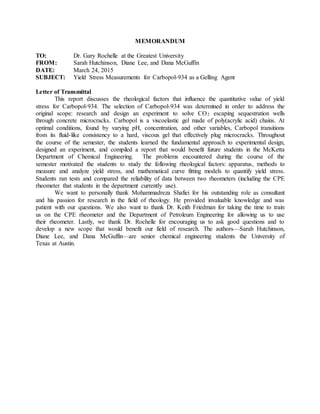
Model Fitting
Yield stress varies by large errors even with accurate measurements because the shear
stress range for each test and the model used to analyze and fit the data is vital to calculating yield
stress. For this C-934 formulation (3 wt% and 9.83 pH), 278 Pa is the predicted reference yield
stress to analyze the accuracy of applying models to each data set (Shafei, 2015).Figure 12 shows
two separate stress ramps using rheometer two, in which each data set is fit to the Herschel-
Bulkley model with an R-squared value greater than 0.99. Test one and two both use 3 wt% C-934
with a pH of 9.83, and the difference between the two tests is the stress ramp range: between 300
and 430 Pa and between 220 and 350 Pa, respectively. The difference in predicted yield stress is
over 100 Pa so that test one, evaluated using higher shear stress values further from the expected
yield stress than test two, is closer to the expected yield stress.
150
250
350
450
550
650
0.001 0.01 0.1 1 10 100
ShearStress[Pa]
Shear Rate [1/s]
Procedure A
Procedure B
21. Figure 12. Herschel-Bulkley model applied to two stress ramp tests under Procedure B with
Rheometer 2 for a 3 wt% C-934 sample as 9.83 pH.
Since both sets of data in Figure 12 fit Herschel-Bulkley extremely well resulting in
extremely different yield stress results, the measured shear rate for one of the tests must not be
valid. The yield stress is less accurate when shear rate is measured at lower shear stress values,
which makes sense based on the theory researched because the necessary relaxation time is higher
when the shear rate is less than 0.01 Hz. Additionally, results from other models used to fit each
test from Figure 12 are shown in Table 1. The Casson and Herschel-Bulkley models fit the data
best for each test.
Table 1. Model fitting to stress ramp tests under Procedure B with Rheometer 2 for a 3 wt% C-934
sample as 9.83 pH.
Yield
Stress Viscosity R2
Yield
Stress Viscosity R2
Yield
Stress Viscosity R2
Pa Pa∙s - Pa Pa∙s - Pa Pa∙s -
1 258.1 136.9 0.99798 248.5 16.9 0.9979 295.6 97.9 0.9855
2 143.8 257.3 0.9944 248.1 123.7 0.85553 259.8 1199.5 0.66583
Model
Herschel-Bulkley Casson Bingham
Test
The Herschel-Bulkley model itself extrapolates the data so that at lower shear rates it will
eventually plateau, but the Casson model assumes the data has reached its plateau within the range
of shear rates analyzed. The difference between the two models is shown in Figure 13, in which
only the data valid data was analyzed for each test. The measurement points at low shear rate
values which decreased at a higher slope than the previous measurement point were removed since
the flow curve should be leveling off and not decreasing at low shear rates. The data shown as
Procedure B using Rheometer 1 is the same flow curve introduced in Figure 11. From Figure 13, it
is easy to see why Casson fits typically result in a lower R-squared value - the Casson model tries
to fit the linear portion of a flow curve to the region that begins its plateau.
22. Figure 13. Herschel-Bulkley and Casson model applied to valid shear rate range of two stress
ramp tests under Procedure B for a 3 wt% C-934 sample as 9.83 pH.
Instrument Effect on Results
The final decision variable for this experiment is choosing the instrument used. Figure 14
shows the results from the two rheometers investigated. Both sets of data were obtained using
Procedure B, however Rheometer 2 varied with decreasing stress ramp tests while Rheometer 1
varied with increasing stress ramp tests. The negative observations for a decreasing stress ramp
from Rheometer 1 were not reproduced using Rheometer 2, therefore a decreasing stress ramp
with Rheometer 2 is a good comparison for the increasing stress ramp with Rheometer 1. Since the
stress ramp with lower shear stress on Rheometer 1 shows that there is a shear rate detection
limitation on Rheometer 1, any data with a measured shear rate lower than 1E-3 Hz cannot be used
in a yield stress analysis.
23. .
Figure 14. Stress ramp tests under Procedure B using rheometers 1 & 2 for a 3 wt% C-934 sample
at 9.83 pH.
From the Herschel-Bulkley fit shown in Figure 13, Rheometer 1 predicts the yield stress
more accurately than Rheometer 2. However, significantly less data points were used from the test
on Rheometer 2 compared to the test on Rheometer 1, so it is not clear that Rheometer 1 is the
better instrument to predict yield stress.
Effect of Slippage
All results shown are for stress ramp tests in which the rheometer had sandpaper attached
to the upper and base plate to reduce sample slippage. If the sample was slipping on the plates, the
measured shear rate would change at low shear stress depending on the measuring gap set. Figure
15 shows the shear rate measurement difference between a 1 mm and 1.6mm measuring gap with
and without sandpaper. The red curve is less than the blue curve for most of the stress ramp, and it
is at least one order of magnitude lower for applied shear stresses lower than 345 Pa. This
indicates that sample slippage is reduced by adding sandpaper to the apparatus.
200
220
240
260
280
300
320
340
360
380
400
1.E-05 1.E-04 1.E-03 1.E-02 1.E-01 1.E+00 1.E+01
ShearStress[Pa]
Shear Rate [1/s]
Rheometer 1
Rheometer 2
24. .
Figure 15. Shear rate difference between 1mm & 1.6mm measuring gap under Procedure B using
Rheometer 1 for a 3 wt% C-934 sample at 9.83 pH.
Recommendations & Conclusions
During the experiment, conditions necessary to accurately measure yield stress from a
stress ramp were investigated: ramp direction, measurement time interval, shear stress applied,
model to fit to results, and apparatus to collect data. An increasing stress ramp should be used, but
this result may depend on the instrument since it is a result of inconclusive results when the shear
stress is decreased. Also, the amount of time per shear rate measurement needs to be as high as
possible for the material to reach equilibrium. Thus, Procedure B is recommended for each range
of shear stresses investigated since it allows the material to reach equilibrium with a reasonable
amount of time per test. Then, the optimal range of shear stress was determined based on the
validity of the shear rate measurement and how well the models fit the data. The best fit, using
Herschel-Bulkley model, occurred when the shear stress was close to the maximum shear stress.
Finally, both rheometers determined a yield stress using the above parameters.
Based on the above conclusions, if Rheometer 1 is used, an increasing stress ramp under
Procedure B is recommended to accurately estimate yield stress as long as the measured shear rate
is about 0.01 Hz. If Rheometer 2 is used, a stress ramp under Procedure B is recommended as long
as the measured shear rate is above 0.001 Hz . Both Rheometer 1 and 2 are acceptable instruments
to produce flow curves that accurately estimate yield stress. This conclusion is important since the
software capabilities, shear rate limitations, and instrument age make Rheometer 2 seem superior
to Rheometer 1. Rheometer 1 predicts yield stress as well as Rheometer 2 despite the following
1.E-04
1.E-03
1.E-02
1.E-01
1.E+00
1.E+01
300 320 340 360 380 400 420 440
ShearRateDifference[1/s]
ShearStress [Pa]
Without Sandpaper
With Sandpaper
25. limitations: cannot measure shear rate less than 0.01 Hz, does not include a tolerance to determine
if each measurement is valid, and data must be exported to an analysis software.
Appendix
Safety
Hazards
The safety hazards for this experiment include those from the materials used and those
from the methods and instruments implemented. C-934 has only a few inherent hazards because
the National Fire Protection Association (NFPA) has rated it a 1 for flammability (combustible if
heated) and a 0 for health, reactivity, and special hazards. The polymer is in a fine powder before
mixing with water, so it is easily inhaled accidentally. Also, the maximum storage temperature is
176 °F. There are some hazards if C-934 is inhaled since it forms a gel with liquid. Students will
use a 1M NaOH solution prepared by the primary consultant, which is caustic since significant
burns can occur when contacting skin.
In addition to the materials used, the instruments also contribute to the safety hazards. The
mixer can potentially splash polymer solution into students’ eyes, and it may become sticky
depending on the C-934 concentration. Both the mixer and rheometer include rotating parts, so
any loose clothing or hair could get caught. The instruments are also operated in close proximity
to water sources and sinks, so there is an electricity hazard. Last, the rheometer may overheat, so it
is equipped with cooling water to keep it near room temperature.
Safety Plan and Disposal
Prior to doing experiments in the lab, students took these safety courses: OH 101 Hazard
Communication and OH 202 Hazardous Waste Management online, and OH 102 Site-Specific
Hazard Communication. Further, students received specific rheometer equipment operation and
safety training. In both working labs, students determined the route of escape in an emergency and
identified the location of the safety showers and eyewash stations. The Material Safety Data Sheet
(MSDS) for NaOH and C-934 were printed and read to ensure knowledge of the hazards. The
students will wear respiratory masks when handling the C-934 to avoid inhaling the particles.
Since the NaOH is caustic, students prepare to use gloves. Students will wear goggles to avoid
materials from entering the eyes. To reduce splashing while mixing, students will initiate mixing
at slow speeds and increase the mixer speed as the viscosity increases. Students will be cautious of
the mixer location in the glass beaker when mixing the gel which will reduce the chance of
breaking the beaker.
The gel will be transported from CPE 5.132 to 4.120 in small sealed glass containers
placed in a large carrying caddy. The student carrying the caddy will wear one glove to protect the
student from materials and use the hand without the glove to open doors. Students will tie back
hair to avoid catching the moving parts of the mixer or rheometer. While using the rheometer and
mixer, students will be cautious of the location of liquids and the electrical sources. With the
rheometer, students will ensure the cold water bath is running consistently to avoid overheating
the rheometer and if the cold water bath is not on or working properly, students will not use the
rheometer until the problem is solved. Students will use the specific disposal container for the C-
934 in the lab. Once the majority of the solution is disposed, the beaker and equipment will be
washed with water.
26. Worse Case Scenarios
The students could ingest too much C-934 if the masks are not worn or are not working
properly, or if the mixer is set at a high speed to start out with and the polymer flies into the air. In
this case, the students will get treatment symptomatically by finding medical attention.
Additionally, the students could spill NaOH on themselves or in their eyes. In this case, the
students will wash the affected skin with soapy water and use the eyewash station.
Specifics on Apparatus and Procedures
Figure 16. Experimental impeller and shaft (“Identification, gel formation test”, 2010).
Figure 17. Calibrated pH probe.
Table 2. Specifications of the rheometer
Manufacturer Anton Paar
Series Physica MCR
Model number 300
Serial Number 387606
Table 3. Specifications of parallel plate 25
27. Manufacturer Anton Paar
Serial # 542
Part # 79044
Diameter (mm) 24.92
Concentricity (μm) 15
Parallelity (μm) 4
Date (mo-day-yr) 09-03-2000
Rheometer (US200) Program Settings
Students used Figure 18 to initialize the rheometer, zero-gap (with sandpaper), change the
measuring position, lift the measuring plate, and lower the measuring plate.
Figure 18. Main setup or settings window for the rheometer.
Students used Figure 19 to determine the max stress without slipping at constant stress and set the
conditioning (or pre-shear) condition as program, Interval 1.
Figure 19. Window to set constant shear stress to condition the sample.
28. Figure 20 is identical to Figure 19 above, except that it is interval is Interval 2, which signifies that
it is the second programed trial. Students set the “Profile” to Ramp log which increases the shear
stress from 300 to 700 Pa logarithmically.
Figure 20. Window to program stress ramp test.
With Figure 21, students set the number of measuring points, “Meas. Points”, the time between
each point, “Duration > Meas. Point”, and the total time interval, “Interval”.
Figure 21. Window to set the number of points for a specific time interval.
Figure 22 shows the two intervals run (Interval 1 and 2) which was programed from Figure 18 to
Figure 21.
29. Figure 22. Window to view programmed tests.
Rheometer (TA Instruments) Specifications
Figure 23. Detail on TA Instruments rheometer and serial number.
Further detail on the difference between Rheometer 1 and 2 software
Rheometer 1 can be programmed to take X points for Y amount of time and the data will
be one average of the X points and in contrast, Rheometer 2 can be programed to average X points
but the subsequent point must be less than a set tolerance of Z%. Since there is a possibility that
30. the rheometer would run for an infinite amount of time to obtain the subsequent point, a maximum
time is set and the point is accepted even if it is greater than Z% tolerance. If the point reaches the
maximum measurement time, the software will show the tolerance at the points.
Data
Table 4. Raw data from Rheometer 1 using Procedure A (after pre-shearing).
Measuring
gap:
time [s]
shear rate
[1/s]
shear
stress [Pa]
60.5 0.1980 300
61.0 0.0860 300
61.5 -0.0265 300
62.0 0.0268 301
62.5 0.0158 301
63.0 0.0085 301
63.5 0.0126 301
64.0 0.0104 301
64.5 0.0086 302
65.0 0.0084 302
65.5 0.0083 302
66.0 0.0083 302
66.5 0.0075 303
67.0 0.0066 303
67.5 0.0064 303
68.0 0.0064 303
68.5 0.0064 303
69.0 0.0065 304
69.5 0.0063 304
70.0 0.0056 304
70.5 0.0052 304
1.5 mm with sandpaper
Table 5. Raw data from Rheometer 2 using Procedure B. Note: Double click on Table 2 to
reference complete Excel results
32. Measurement Date: 27-Mar Instrument: Physica MCR300
Stress
Shear
rate
|Shear
rate|
Viscosity
Calculated
Viscosity
Step
time
Tempera
ture
Pa 1/s 1/s Pa.s Pa.s s °C
Test1 - 1.6 mm Meas Gap
430 0.0986 0.0986 4,360 4,361 240 23.3
415 0.0717 0.0717 5,790 5,788 360 23.3
400 0.0391 0.0391 10,200 10,230 480 23.3
400 0.0449 0.0449 8,910 8,909 660 23.4
395 0.0342 0.0342 11,500 11,550 840 23.6
389 0.0355 0.0355 11,000 10,958 1,020 23.7
384 0.0291 0.0291 13,200 13,196 1,200 23.8
379 0.0254 0.0254 14,900 14,921 1,380 23.9
374 0.0216 0.0216 17,300 17,315 1,560 23.9
368 0.0171 0.0171 21,600 21,520 1,740 23.9
363 0.0176 0.0176 20,600 20,625 1,920 23.8
358 0.0182 0.0182 19,600 19,670 2,100 23.7
353 0.0185 0.0185 19,100 19,081 2,280 23.7
347 0.0203 0.0203 17,200 17,094 2,460 23.7
342 0.0206 0.0206 16,600 16,602 2,640 23.7
337 0.019 0.019 17,700 17,737 2,820 23.8
332 0.0174 0.0174 19,100 19,080 3,000 23.9
326 0.0151 0.0151 21,600 21,589 3,180 24
321 0.0146 0.0146 22,000 21,986 3,360 24
Sample Calculations
The experimenters calculated the mass of C-934, 𝑚 𝑐934 grams, necessary to make a 3 wt%
polymer solution based on the calculations below where 𝑉𝑤 is the mL of water used. For a solution
from 500 mL water, the weight of C-934 is shown below.
0.03 =
𝑚 𝑐934
𝑚 𝑐934 + 𝑉𝑤
𝑚 𝐶934 =
0.03 ∗ 500
0.97
= 15.464 𝑔 𝐶𝑎𝑟𝑏𝑜𝑝𝑜𝑙 934
Additionally, the rheometer used the measured shear rate (𝛾̇) and shear stress (𝜎) to calculate the
viscosity (𝜇) by the calculation shown below. The calculation of the second data point of the
sample measured with a 1 mm gap with sandpaper is shown. The rheometer does this calculation
internally.
𝜇 =
𝜎
𝛾̇
𝜇= 300 𝑃𝑎0.0354 1𝑠
33. Effort report
Student: Sarah Diane Dana All
In Lab (all) 30 32 35 97
Prgress Report 12 12 12 36
Final Report 10 7 12 29
Total 52 51 59 162
Number of Hours put in
34. References
Brookfield Engineering. (2015). Wells-Brookfield Cone/Plate. Retrieved April 21, 2015, from
http://www.brookfieldengineering.com/products/viscometers/laboratory-wb-coneplate.asp
Callister, W. D., Jr, & Rethwisch, D. G. (2010). Materials Science and Engineering (8th ed.). John
Wiley & Sons.
Carbopol® 934 polymer. (2015). Retrieved March 13, 2015, from
https://www.lubrizol.com/PersonalCare/Products/Carbopol/Carbopol934.html.
Christel, M., Yahya, R., Albert, M., & Abboud Antoine, B. (2012). Stick-slip control of
Carbopobol microgels on polymethyl methacrylate transparent smooth walls [Abstract].
Royal Society of Chemistry, 8, 7365-7367.
Di Giuseppe , E., Corbi , F., Funiciello, F. et al. (2015). Characterization of Carbopol® hydrogel
rheology for experimental tectonics and geodynamics. Tectonophysics, 642, 29-45.
http://dx.doi.org/10.1016/j.tecto.2014.12.005
Duguid, A. (2006). The effect of carbonic acid on well cements (Order No. 3236173). Available
from ProQuest Dissertations & Theses Full Text. (305250606).
Hassan MA, Pathak M, Khan M. Thermorheological Characterization of Elastoviscoplastic
Carbopol Ultrez 20 Gel. ASME. J. Eng. Mater. Technol.. 2015;137(3):031002-031002-8.
doi:10.1115/1.4030004.
Fernandez-Nieves, A., Wyss, H., Mattsson, J., & Weitz, D. A. (Eds.). (2010).
Microgel Suspensions Fundamentals and Applications. Wiley.
Franck, A. J. (Ed.). (2004, August). Understanding rheology of structured fluids (Technical Report
No. 10-04V1). TA Instruments.
Gutowski, I. (2008). The effects of pH and concentration on the rheology of carbopol gels
(Unpublished master's thesis). McGill University, Quebec, Canada.
Identification, gel formation test [PDF]. (2010). Retrieved from
https://www.lubrizol.com/Personal-Care/Documents/Test-Procedures/Carbopol®-
Rheology-Modifiers-and-Pemulen™-Emulsifiers-Test-Procedures/TP-SA-027-Carbopol-
Pemulen-Noveon-Identification-Gel-Formation.pdf
Larsson, M., & Duffy, J. (2013). An overview of measurement techniques for
detmerination of yield stress. Annual Transactions of the Nordic Rhology
Society, 21.
Self-sealing cracks with superabsorbent polymer. (2015, January 1). Retrieved February 21, 2015,
from http://www3.imperial.ac.uk/concretedurability/researchprojects/selfsealingconcrete
TA Instruments. (2015). Peltier Solvent Trap [White paper]. Retrieved April 21,
2015, from http://www.tainstruments.com/main.aspx?siteid=11&id=325&n=1