neemuch Call Girls 👙 6297143586 👙 Genuine WhatsApp Number for Real Meet
3.J Pharma monitoring of HVAC systems.docx
1. 3.J Pharma monitoring of HVAC systems
Up20 Rainer Röcker, Hans H. Schicht, PhD
Here you will find answers to the following questions:
● What is the purpose of the pharma monitoring of HVAC systems?
● What distinguishes pharma monitoring systems from the automatic control -systems of HVAC systems?
● Which particularities apply to the management of pharma monitoring data?
● Which physical and microbiological parameters require monitoring?
● What is the objective of alert and action limits?
● What has to be considered when operating and maintaining HVAC systems?
● How can the validation of pharma monitoring systems be performed efficiently -according to GAMP 5?
3.J.1 Objectives of pharma monitoring
Up20 Dr. Hans H. Schicht
In the context of monitoring pharmaceutical production processes, i.e. the collection and recording of production-
relevant data, the collection, recording and storage of data regarding air cleanliness and other parameters related to the
air in production rooms is frequently required. Distinction must be made between
● data relevant for product quality and safety which require compliance and incorporation into the batch documentation,
and
● data whose measurement and compilation is necessary for maintaining the correct function of the HVAC system.
Data important for product quality and safety must be collected, processed, recorded and stored in the pharma
monitoring system of the HVAC system, which is an integrated element of the general pharma monitoring system of
the production process. On the other hand: collection, processing, recording and storage of technical data relevant for
the correct and stable operation of the HVAC system is the responsibility of that system's automatic control
system which frequently is integrated into the general building managementsystem of a facility.
3.J.2 Data management in pharma monitoring
Up20 Dr. Hans H. Schicht
Data proving the correct and stable operation of the HVAC system are an essential element of quality assurance in the
context of manufacturing sterile and other sophisticated pharmaceutical products. As a consequence, such data
become an integral part of the batch documentation. Which data require collection and recording, and to what extent,
must be decided case-specifically for each production task. Computerized systemsare employed for continuous or at
least frequent collection, processing and storage of quality relevant data. Such computerized systems are required to
meet the regulatory requirements stipulated in Annex 11 to the EU GMP Guide (see Chapter C.6.11) and in the
respective FDA determinations compiled in 21 CFR 11 and related guidelines (see Chapter D.1.3, Chapter
D.7 and Chapter D.12).
Computerized systems of this kind require validation (see Chapter 9 Computer System Validation). The most
appropriate base for doing so is the exhaustive GAMP 5 Guideline edited by ISPE, the International Society for
Pharmaceutical Engineering. The regulatory authorities of Europe and the USA have contributed substantially to the
preparation of this guideline. You will find an example for the validation of a monitoring system according to the “V-
model” described in GAMP 5 in Chapter 3.J.6 Validation of a monitoring system in accordance with GAMP® 5.
Core elements of computerized data protection schemes are:
● Only authorized persons must be capable of entering data into the system and for changing them
● Unauthorized persons must not be able to enter into the system
● Data must be protected against accidental or willful damage and against loss
● Data storage must meet stringent safety criteria
● Records and signatures must be safeguarded against falsification
Access to data must be assured for a long period of time: at least well beyond the expiry date of the product. In many
nations also legislative requirements for data storage must be observed.
Automatic control systems of HVAC systems and the superior building management systems are, as a rule, not capable
of being validated – due to their extensive ramifications throughout the entire building complex of a site. Therefore, it is
imperative that data management for process monitoring purposes be completely independent from the building control
system: it must be impossible for the building control system to interfere into process monitoring. Persons authorized for
interference into the building control system will, as a rule, not have access to the pharma monitoring system.
2. Buildings and their HVAC systems employed, for example, for the manufacture of sterile products, will require
monitoring of both physical and microbiological parameters. At today's state-of-the-art only physical measurement
parameters permit data collection, recording, evaluation and long-time storage by means of automatic computerized
systems. Automatic alarms are therefore based on physical data only. It appears likely, however, that instantaneous
microbiological detection methods which record air-borne particles via electronic signals (Jiang 20091) will sooner or
later permit automated microbiological air monitoring (Bjerner et al. 20122).
Measurement instruments utilized in the context of pharmaceutical process monitoring for data collection of physical
and microbiological parameters must be recalibrated in periodical intervals, independently whether they are
incorporated into computerized monitoring systems or serving for periodical manual measurements. The interval
between recalibrations is normally one year.
Where the continuous collection of measurement data makes little sense or where this is impossible due to fundamental
reasons – as, for example, data collection with present-day microbiological procedures – measurements may be
performed and recorded manually. A physical parameter for which manual measurement is indicated is surveillance of
the pressure difference between the upstream and the downstream side of HEPA filters. Here quarterly, half-yearly and
even annual data recording is sufficient.
1
Jiang J.P.: How instantaneous microbial detection can be used by pharmaceutical manufacturers. Eur J Parenter
Pharm Sci 14 (2009) 4, 103–109
2
Bjerner G. et al.: Real-time microbiological air monitoring. Eur J Parenter Pharm Sci 17 (2012) 2, 52–55
3.J.3 Physical monitoring of cleanrooms
Up20 Dr. Hans H. Schicht
3.J.3.1 Standards and guidelines
As normative fundament for the monitoring of cleanroom systems the Draft International Standard ISO/DIS 14644-2.2
“Monitoring to provide evidence of cleanroom performance to air cleanliness by particle concentration” published in
September 2014 is recommended above all, as it reflects the present state-of-the-art comprehensively. In addition, the
German guideline VDI 2083 Part 3.1 “Cleanroom technology – Metrology in cleanroom air – Monitoring” (www.beuth.de)
is also appropriate for being used for this purpose. Only parameters which are of general relevance in the context of
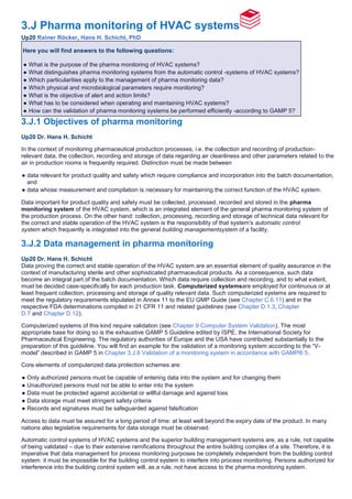
pharma monitoring of HVAC systems will be discussed below. There are two types of data to be distinguished
(see Figure 3.J-1). It makes sense to incorporate into the pharma monitoring system also the functional control of air
lock doors and their alarms.
Figure 3.J-1 Data types for pharma monitoring
Data type 1 Data type 2
Recording
frequency
continuous or frequent periodical
Recording
procedure
automatic manual
Examples ● Maintenance of positive or negative pressure
● Temperature and relative humidity of air
● Particle concentrations in grade A and B
areas
● Particle concentrations in grade C and D
areas
● Pressure difference across HEPA filters
3.J.3.2 Alert and action limits
In order to ensure early warning against any problems developing during the operation of the HVAC systems, other
utilities and the processing equipment, alert and action limits (see Figure 3.J-2) should be determined for the key
physical parameters requiring monitoring. By means of a two-step approach to developing excursions of monitoring
data, alerting thus also provides a sound and objective input for trend analyses of process and cleanroom performance.
Figure 3.J-2 Two-step approach alerting to excursions of monitoring data
3. Two-step approach alerting to excursions of monitoring data
Alert
limit
A predetermined value somewhat outside the normally expected tolerance band. If exceeded, intensified
supervision according to a pre-determined plan should be triggered.
Action
limit
A predetermined value substantially outside the normal tolerance band. If exceeded, immediate formal action
according to a predetermined plan specifying the necessary investigative and corrective actions is to be
triggered.
How to establish alert and action limits? Taking the pressure difference between rooms as example, the limits shown
in Figure 3.J-3 will assure that even in the worst case no flow reversal will occur at the action limit: there is still a
pressure difference of 3 Pa available for ensuring that. If the 30 Pa Δp value falls to its lower action limit, i.e. to 24 Pa
and the 15 Pa Δp value rises to its upper action limit, i.e. to 21 Pa, there is still a pressure difference of 3 Pa available
for assuring that.
Figure 3.J-3 Proposal for alarm and action limits for pressure differentials
Term Δp = 15 Pa Available differential (worst case) Δp = 30 Pa
Set point 15 Pa 15 Pa 30 Pa
Control tolerance 15 Pa ± 3 Pa 9 Pa 30 Pa ± 3 Pa
Alarm limit 15 Pa ± 4.5 Pa 6 Pa 30 Pa ± 4.5 Pa
Action limit 15 Pa ± 6 Pa 3 Pa 30 Pa ± 6 Pa
Alarms due to exceeding the alarm and action limits of control parameters should be transmitted to the computerized
pharma monitoring system and registered there inextinguishably. Alarms should be triggered individually when alert or
action limits are exceeded and should be recorded indelibly in electronic form.
In addition to these alarms alerting to serious excursions of control parameters also alarms triggered by incidents like
airlock doors being kept open for too long should be incorporated into the automatic alarm module of the pharma
monitoring system.
3.J.4 Microbiological monitoring of cleanrooms
Up20 Dr. Hans H. Schicht
Besides the above mentioned physical parameters, all microbiological measurement parameters are subject to
periodical measurement and assessment. Such microbiological parameters are particularly important in the context of
process control of sterile processing operations, however there are cases even in non-sterile production where such
data should be collected and stored.
3.J.4.1 Regulatory requirements
Regarding microbiological monitoring of sterile manufacturing operations, differences exist between European and US
requirements: In its Guidance for Industry on Sterile Drug Products Produced by Aseptic Processing (see Chapter
D.10), FDA requires only the active sampling of airborne microorganisms, complemented by measurement of microbial
sedimentation as an optional test (see Chapter 3.C.2 GMP Requirements for Cleanrooms: Air Cleanliness Grades).
Annex 1 to the EU GMP Guide, on the other hand, includes the sedimentation test into the specified monitoring
parameters, and also requires surface cleanliness tests of critical processing areas as well as the testing of sterile
gloves if they serve for interference into Grade A areas (see Figure 3.C-2 for limit values).
Very comprehensive guidance on microbiological monitoring is compiled in the informative chapter <1116> of the U.S.
Pharmacopoeia. This chapter has been completely revised for USP 35 and was renamed to “Microbiological control
and Monitoring of Aseptic Process Environment”. At this time, an entirely different approach has been adopted for the
establishment of microbiological limit values for sterile production processes. Instead of setting limit counts of colony
forming units, preference is given to assessing the percentage of samples (identified as incident rate) on which
microbiological contamination has been detected after due incubation. The following definition is given: “The incident
rate is the rate at which environmental samples are found to contain microbial contamination. For example, an incident
4. rate of 1 % would mean that only 1 % of the samples taken show any contamination regardless of the colony number. In
other words, 99 % of the samples taken are completely free of (microbiological) contamination”. The contamination
incident rates recommended in the informative chapter <1116> are given in Figure 3.J-4.
Figure 3.J-4 Recommended contamination incident rates according to the USP Informative Chapter <1116>2
Air cleanliness class1
Active air
sampling
Settle plate (4 hrs
exposure)
Contact plate or
swab
Glove or
garment
Isolator (ISO class 5 or
better)
< 0.1 % < 0.1 % < 0.1 % < 0.1 %
ISO class 5 < 1 % < 1 % < 1 % < 1 %
ISO class 6 < 3 % < 3 % < 3 % < 3 %
ISO class 7 < 5 % < 5 % < 5 % < 5 %
ISO class 8 < 10 % < 10 % < 10 % < 10 %
1 Cleanliness class for airborne particles according to ISO 14644-1
2 All operators are aseptically gowned in these environments (with the exception of background environments for
isolators). These recommendations do not apply to production areas for nonsterile products or other classified
environments in which fully aseptic gowns are not donned.
The frequency of microbiological sampling should be determined according to the level of risk and can vary from more
than once per batch or shift to once every three months or every half year. USP, for instance, recommends in its
informative chapter <1116> the sampling frequencies given in Figure 3.J-5 for aseptic processing areas.
Figure 3.J-5 Frequency of sampling in aseptic processing areas as recommended in the USP informative chapter
<1116> (see footnote 2 of Figure 3.J-4)
Sampling Area / Location Frequency of sampling
Cleanrooms / RABS
Critical zone (ISO class 5 or better)
Active air sampling Each operational shift
Surface monitoring At the end of the operation
Aseptic area adjacent to critical zone
All sampling Each operational shift
Other nonadjacent aseptic areas
All sampling Once per day
Isolators
Critical zone (ISO class 5 or better)
Active air sampling Once per day
Surface monitoring At the end of the campaign
5. Nonaseptic areas surrounding the isolator
All sampling Once per month
3.J.4.2 Risks of microbiological monitoring
At today's state-of-the-art microbiological sampling is predominantly performed manually and with procedures which,
strictly speaking, cannot be considered as sterile. As a consequence, such sampling procedures have to be ranked as
process risks! This problem merits attention above all in the context of the new advanced processing technologies with
enhanced sterility assurance levels such as isolator or RABS technology (see Chapter 3.E Barrier systems, isolators
and safety cabinets).
The topic of microbiological sampling as a process risk is only addressed summarily in Annex 1 of the EU GMP Guide:
with a brief statement that sampling methods used in operation should not interfere with zone protection. This issue is,
however, addressed more extensively in the informative chapter <1116> of the U.S. Pharmacopeia, for instance with
the statement: “Microbiological monitoring is usually performed by personnel and thus requires operator intervention. As
a result, environmental monitoring can both increase the risk of contamination and also give false-positive results.”
Once comprehensive qualification and validation have established the effectiveness of the protection concept in
controlling the microbiological risks, for example in the case of ultra-high safety protection concepts (e.g. isolator or
RABS technology), then a comparatively low frequency of sampling for routine process monitoring can be adopted. This
frequency must, of course, under all circumstances match the batch documentation requirements. This shift of the
determination of the Sterility Assurance Level from monitoring to the upstream qualification and validation activities is
another argument in favour of comprehensive qualification and validation efforts.
For assuring that this qualification and validation status is maintained during the entire life cycle of the production
process, periodical media fills are a most effective procedure.
3.J.4.3 Alert and action limits
Regarding microbiological monitoring, USP considers, in its revised informative chapter <1116>, the establishment of
alarm and action limits as meaningless, due to the inherent variability between different active sampling devices.
More information on the topic of microbiological monitoring can be found in Chapter 12.J Microbiological monitoring.
3.J.5 Operation and maintenance
Up20 Dr. Hans H. Schicht
In order to avoid the infiltration of false air into contamination controlled facilities or premises, the corresponding HVAC
systems should run continuously. This is an absolute must for premises where specified air cleanliness classes or room
grades require to be met. However, it is well feasible to reduce the air flow rate of the HVAC system outside production
hours, for example, in facilities with single-shift utilization. Such a reduction is a potent saver in energy costs and
therefore merits serious consideration in the determination of the operational strategy for the HVAC system.
Of course, the predetermined pressure differences between rooms as well as the air cleanliness classes and air flow
patterns stipulated for the at rest occupancy state must be maintained uninterruptedly during system operation with
reduced air flow rate. This also applies to the transition from one operating status to the other.
Important guidance for operation and maintenance of pharmaceutical cleanroom systems can be found in the
international standard ISO 14644–5 and in the German guideline VDI 2083 Part 5.1 complementing the ISO
determinations.
3.J.6 Validation of a monitoring system in accordance with GAMP® 5
Up20 Rainer Röcker
Pharmaceutical manufacturers are "regulated companies" that have to meet the currently valid GxP requirements. If
computer-aided systems are used, their compliance and suitability for the intended purpose must be ensured during the
complete system life cycle. The risk-based specification, implementation and subsequent verification correspond to the
validation of the system. Validation is also mandatory for monitoring systems that are classified as category 4 systems
in accordance with GAMP 5. These systems are measurement data recording systems that require a high degree of
data security in order to record, transmit and save quality-related measurement data. If the limit values are exceeded,
alarms are triggered to ensure that the operator can remedy unwanted situations immediately (see also Chapter 24.J.5
Alarm system).
GMP requirements for validation of computerised systems can be found in the EU GMP Guidelines (in particular Annex
11 and Annex 15) and in 21 CFR Part 11. The principles of risk management as described in ICHQ9 should also be
followed. The implementation of these requirements is a fastidious task. Guidance for implementation is provided by
GAMP5.
6. The aim of this article is to describe a procedure for a validation strategy which is both cost-efficient and compliant using
the example of a monitoring system for measurement data.
3.J.6.1 Application areas for monitoring systems
Monitoring systems are used in the pharmaceutical industry when parameters such as differential pressure,
temperature, moisture, etc. are relevant to the quality of the product and must be documented completely from start to
finish. These include
● Clean rooms (in accordance with EU GMP Guidelines, Annex 1 and DIN ISO 14644),
● Test chambers, refrigerators and incubators (in accordance with national -accreditation bodies),
● Transportation vehicles and medicinal product stores (in accordance with the EU GDP guidelines)
The new GDP guideline (see Chapter C.14), in particular, demands documented evidence proving that medicinal
products have been stored and transported in such a way that the quality of the medicinal product was not negatively
affected. It is vital that temperature distribution measurements (temperature mapping) or qualification is carried out on
the devices and storage areas outlined above. For transportation vehicles and storage facilities, a winter and a summer
mapping should be carried out.
The results can then be used to derive the positions for the data loggers based on risk and to define the alarm limits.
These results can also be used for construction measures, i.e. installation of a heating, ventilation or air conditioning
system, in order to meet the storage requirements.
3.J.6.2 Basic functions of and requirements for a modern monitoring system using a warehouse for medicinal
products as an example
Temperature and moisture are measured and recorded using so-called data loggers (see Chapter 24.J.1 Temperature
monitoring during transport and Chapter 24.J.2 Temperature loggers). The recording intervals depend on the individual
process and the stored product. In practice, the standard recording intervals are normally 15 minutes. This applies to
both cool storage (2–8°C) and storage at room temperature (15–25°C).
The data logger must have sufficient memory. There must be no loss of data and data must not be overwritten before it
has been evaluated and permanently stored on the server. This data is then transmitted to a base station using an
Ethernet interface or radio transmission. The base station must be able to trigger an alarm and save a large amount of
data even if a server is not used. This ensures maximum data security and integrity. The base station transfers the data
to the server. It should be possible to send an alarm from the server via email. Network-compatible software, e.g. SQL
database, completes the system, which displays the data without risk of manipulation, generates PDF reports and is
able to send an alarm via email.
The basic functions of this type of monitoring system are shown in Figure 3.J-6.
Figure 3.J-6 Overview of the basic functions of a monitoring system
7. As this is an automatic electronic data capture and storage application, the regulations in 21 CFR Part 11 (FDA
regulations ensuring secure data storage and the prevention of data manipulation) apply.
The following list summarises the most important requirements for a monitoring system:
● Calibrated data loggers with sufficient memory
● Data transmission via Ethernet or radio
● Base station with its own alarm that is triggered even when a server fails, e.g. visual or acoustic alarm or alarm via
SMS
● Base station with sufficient memory to store all measurement data over an extended period of time
● Data evaluation using graphics and tables
● Automatic reporting
● Data access control
● User authorisation concept
● Audit trail with complete history
● Large database
● Server mirroring
3.J.6.3 Implementation of the validation in accordance with GAMP 5
The overall objective of regulatory requirements concerning validation is to ensure product quality and thus patient
safety. Unfortunately, validation is still often seen as merely adhering to documentation requirements, but in fact, it is
much more: the benefits of validation are shown in Figure 3.J-7.
Figure 3.J-7 Benefits of validation
The V model in accordance with GAMP 5 shown in Figure 3.J-8 has proven successful when carrying out the
validation. The individual steps are described below.
Figure 3.J-8 V model in accordance with GAMP 5 (Source: GAMP 5, Annex M3)
8. Initial risk assessment
Before a requirement specification is created, an initial risk assessment should be carried out to determine and define
the basic risks for the company, process and finally the product. For example, if medicinal products are stored in a high-
bay warehouse, it is necessary to record the temperature from start to finish and an alarm is required that triggers if the
permitted temperature limits are exceeded.
The initial risk assessment is used as a basis for decision-making when purchasing a system. Its objective is to
minimise or eliminate risks.
The details of the initial risk assessment must be reflected by the user requirements specification. This also applies for
the decision on carrying out a functional risk assessment.
User requirements specification
The user requirements specification (URS) is the basis for the tender and qualification. It is important to invest sufficient
time in this process. At a later phase of the project, it is difficult and/or costly to return to points that were forgotten or not
taken into consideration during this early phase. It should also be kept in mind that the quality of the offer made by a
potential supplier can only be as good as the user requirements specification. It is, unfortunately, common practice to
copy requirements specification documents from previous projects that do not always match the application in question.
This is often difficult for the system suppliers because they have to comment on every single point. The following is also
very important:
● SAT approval
● System maintenance
● Service agreement
● Training
These points are often forgotten because of the tendency to focus on the functional requirements.
Supplier audit
Before any decision is made on the choice of supplier, an inspection must be carried out to ensure that QA processes
have been defined and implemented in the company. An ISO 9001 certificate alone is not sufficient. It must also be
ensured that the GMP requirements for pharmaceutical suppliers are being met.
Suppliers of critical machinery must undergo an on-site audit, whereas a postal audit can suffice for suppliers of less
critical machinery. A catalogue of questions when carrying out an audit of either type is extremely helpful.
Typical questions for the audit include:
9. ● Has the supplier installed a functioning QMS?
● How is its proper implementation ensured?
● How are dealings with subcontractors monitored, especially with regard to software development?
● Is there a documented approach that includes standards, especially for software development?
● Is there a software development life cycle right up to decommissioning of the machine?
● Are the sensors calibrated in a certified laboratory?
● Are there reference customers?
● How many systems has the company installed in a pharmaceutical environment to date?
Functional specification
In the functional specification, the contractor should comment on every point of the user requirements specification.
Even when a point is not applicable, it should be included and marked N/A. To ensure traceability, it is important that the
numbering of the individual points is identical to the numbering in the requirement specification. Ideally, user
requirements and functional specifications should be presented face to face in a document. This makes it easier to keep
documents up to date across the entire project.
Figure 3.J-9 shows how user requirements and functional specifications can be juxtaposed.
Figure 3.J-9 Juxtaposition of user requirements specification/functional specification
No.
Process owner requirement (user
requirements specification) Supplier statement (functional specification)
10.1.1 Project planning of overall -system The overall system is being planned in -accordance with the
recommendations in GAMP 5.
10.1.2 Correct installation of the system The system is installed and configured in -accordance with the
specification. The -necessary skilled work has been delegated to proven
specialists.
10.1.3 All sensors must be calibrated and
have a valid -calibration certificate
All of the sensors ordered are supplied after initial calibration and with a
valid calibration certificate. Calibration is carried out in a -certified
laboratory.
10.1.4 Documented commissioning and
inspection of the system
After the system has been installed, it is commissioned. A SAT is carried
out in order to document the quality of installation/commissioning.
10.1.5 Alarm methods if limit -values are
exceeded
The system offers 5 alarm methods: SMS, email, visual, acoustic,
normally open relay contact.
10.1.6 Availability of data when a system
failure occurs
The base station must store the measurement data for a period of 40 days
independently from the server.
10.1.7 Documented and functional restore
process
The process is documented in writing so that IT experts can carry out the
procedure.
10.1.8 Complete evaluation of the records The system does not only provide reports but also data evaluation using
graphics and tables.
10.1.9 Functional audit trail in -accordance
with 21 CFR Part 11
System complies with 21 CFR Part 11 See also White Paper
Configuration specification
The so-called configuration specification was introduced in GAMP 5 and contains information about the individual
system components.
The configuration specification replaced the documents that were previously used; the hardware design specification
(HDS) and the software design specification (SDS). The documents can be left as a draft version until the end, and all
variable data, e.g. software versions, is contained in this document, making the qualification more flexible and more
efficient. There was a time when one had to wait for the document to be released or make changes to documents that
had already been released. This procedure is no longer applicable. This is reflected in Figure 3.J-10.The configuration
specification primarily describes:
● Technical data of the components
10. ● Database specification
● Email exchange server specification
● Firmware versions
● Software versions
● Software configuration
● Sensor settings
● Alarm limit values
● Alarm receivers and cascading
● User authorisation and concept
● Recipient of the automatically generated reports in PDF format
● Sensor names and position
Figure 3.J-10 Left-side process of the V model
Functional risk assessment
The functional risk assessment is carried out based on the functional specification (see Figure 3.J-8). During the
assessment, it is decided which points are GMP-critical and which measures have to be subsequently taken. The
visualisation of the individual process steps is very helpful.
The FMEA method is extremely well suited to carrying out risk assessment of monitoring systems (see Chapter 10.D.8
Failure Mode Effects Analysis (FMEA)). The ICH Q9 provides valuable information on this in chapter 5 Risk
Management Methodology (see Chapter E.9). The degree of severity, the probability of occurrence and the detectability
of each potential error mode is evaluated using a predefined scale. Numeric values of 1–3 and 1–5 are normally used.
Using an evaluation scale of 1–5, a risk priority number of 27 (3 x 3 x 3) can, for example, be defined as a limit value.
Errors with a risk priority number (RPN) >27 can then be classified as critical errors that require the specification of risk
reduction measures.
● RPN < limit value: no measure necessary or only necessary in certain cases.
● RPN ≥ limit value: definition of measures necessary.
A repeat evaluation is carried out taking the defined measures into consideration that result in a new RPN(2). This
RPN(2) must always lie below the critical limit value. If the RPN(2) is too high, measures for reducing risk must be
defined until a value below the critical limit value has been achieved.
Figure 3.J-11 shows an example for a part of this process.
11. Figure 3.J-11 Example of an FMEA (extract)
N
o.
Component/Fu
nction
Potential
error
Potential
conseque
nces of
the error
Potential
causes of the
error
GxP-
criti
cal
Assessm
ent
before
measure
Rational
e
Measure/Com
ment
Assessm
ent after
measure
S O D
RP
N S O D
RP
N2
Commissioning / Configuration
1.
1
Scope of
delivery of
overall system
Incorrect/
missing/
damaged
component
s
System is
not fully
functional
Incorrect
order,
incorrect
delivery
Yes 5 2 4 40 System is
not fully
functional
IQ test 02:
Checking the
scope of
delivery
5 1 2 10
1.
2
Configuration of
all sensors
Configurati
on not as
specified
(e.g.
measureme
nt cycle,
battery
type, alarm
limit, …)
Incorrect
measurem
ent
values/alar
ms
Specification
not observed
Yes 5 3 3 45 Incorrect
measure
ment
values/al
arms
See 1.11 5 1 3 15
1.
3
Alarm
configuration
Configurati
on not as
specified
Incorrect
alarms
Specification
not observed
Yes 5 3 4 60 Incorrect
alarms
IQ test 22:
Checking the
settings for
alarm limit
valuesIQ test
23: Checking
the settings for
the alarm
recipientsIQ
test 24:
Checking the
settings for the
alarm delayIQ
test 25:
Checking the
settings for the
alarm
transmitter
5 1 2 10
Data forwarding (radio, Ethernet, router, converter)
3.
1
Ethernet
communication
base server
Measureme
nt values
are not
forwarded
to the
database
Circular
buffer of
the base
station is
full (note:
after more
than one
year if a
standard
measurem
ent cycle is
used)
Ethernet
network failure
or error (e.g.
voltage failure)
for more than
Yes 5 2 3 30 Circular
buffer of
the base
station is
full
SOP
recommendati
on 04: SQL
server failure
or Ethernet
failure
3 2 1 6
12. 3.
2
Ethernet
communication
server
Email alarm
cannot be
sent
No alarm Ethernet
network failure
or error (e.g.
voltage failure)
Yes 5 2 3 30 No alarm Recommended
measure 03:
Redundant
alarm in the
case of critical
alarms
2 1 2 4
Base station
4.
1
Base/data
storage
Base
station
failure
System
configurati
on data
loss
Hardware
failure (base
station)
Yes 5 2 4 40 Loss of
system
configurat
ion
System server
sends an
alarmSOP
recommendati
on 03:
Component
failure-
converter/route
r/base
3 2 2 12
Compliance with 21 CFR Part 11
5.
1
Software
password
protection
Unauthoris
ed access
is possible
Not
compliant
with 21
CFR Part
11
Password
protection
option not
activated
Yes 5 3 4 60 Not
compliant
with 21
CFR Part
11
OQ test 02:
Checking the -
access
rightsOQ test
13: Checking
that the -
measuring
data entered in
the client
software is
protected from
manipulationO
Q test 14:
Checking that
the -measuring
data entered in
the SQL
database is
protected from
manipulationO
Q test 15:
Checking that
PDF -reports
are protected
from
manipulationO
Q test 16:
Checking that
alarm -
acknowledgem
ent is protected
from
manipulation
5 1 2 10
5.
2
Limited access
for authorised
users
Unlimited
system
access
Not
compliant
with 21
CFR Part
11
Insufficient
configuration
of accounts
Yes 5 3 3 45 Not
compliant
with 21
CFR Part
11
Recommended
-measure 01:
Windows user
accounts
5 1 2 10
5.
3
Closed -system Requireme
nt not met
Not
compliant
with 21
CFR Part
11
User access
not sufficiently
limited
Yes 5 3 3 45 Not
compliant
with 21
CFR Part
11
Recommended
-measure 01:
Windows user
accounts
5 1 2 10
13. 5.
4
Server time Server
system
time is not
correct
(through
automatic
time
synchronis
ation)
Not
compliant
with 21
CFR Part
11
Incorrect
server system
time setting
Yes 5 2 2 20 Not
compliant
with 21
CFR Part
11
Recommended
-measure 12:
System time
system server
5 1 1 5
SOPs, user training courses and especially the test documents of the supplier can be defined as measures along with
the functional tests. In the past, tests often had to be carried out repeatedly. Synergies can now be used. It often makes
sense to formally approve FAT documents and use parts of them for the qualification or as a reference.
A risk-based approach combined with active supplier involvement leads to a cost-effective qualification.
SAT
After the system has been installed successfully at the operator, it is advisable to carry out a comprehensive site
acceptance test (SAT). This shows that the system meets the specified conditions and operates within the system limit
values set. Alarm limit values are often set too narrowly, although the process does not require it. For this reason, the
system should be stable during the SAT and a validation test should only be carried out after successful completion of
the SAT.
Configuration testing
After the SAT has been carried out successfully, the configuration testing (previously known as the installation
qualification (IQ)) can be carried out. It is based on the configuration specification.
Typical tests include:
● System scope of delivery
● Visual inspection of the technical documentation
● Documentation of the installed software versions and backup
● Hardware configuration test
● Software configuration test
● Server configuration test
● Installation of sensors with designation test
● Test of the settings for the alarm transmitter
● Inspection of the calibration certificates
The tests should verify that the system has been configured in accordance with the specification.
Functional testing
The functional testing (previously known as the operational qualification (OQ)) also results from the risk analysis and
checks the functions against the functional specification. It is particularly important that the test preconditions and the
individual steps carried out to achieve the results are clearly described and reproducible. The aim is to achieve the
same result every time using the same process.
Typical tests include:
● Checking the timestamp against the server time
● Checking that the measuring values are transmitted in the signal chain
● Checking that the data is buffered inside the sensors
● Checking that the data is buffered inside the base station
● Checking the alarm triggering function
● Checking the automatic PDF reports and data comparison
● Checking that the measuring data entered in the client software is protected from manipulation
● Checking that the measuring data entered in the SQL database is protected from manipulation
● Checking that the alarm acknowledgement is protected from manipulation
● Checking the system behaviour when a voltage failure occurs
● Checking the restore process
● Checking the backup of data
● Checking for compliance with 21 CFR Part 11 requirements
Figure 3.J-12 shows an example of a possible procedure for implementing the functional tests.
14. Figure 3.J-12 Example of a functional test
OQ-03: Checking the time synchronisation/timestamp against the server time
This check is carried out to ensure that the timestamp of the monitoring CFR software is synchronised with the server
time on a regular basis.
Precondition
OQ-01 carried out successfully
Test procedure
● Start the monitoring CFR client software as a test user
● Change the monitoring system time so that it is 30 minutes slow.
● Wait for 5 minutes, then carry out a visual comparison of the monitoring system time and the server time
● Change the monitoring system time so that it is 30 minutes fast.
● Wait for 5 minutes, then carry out a visual comparison of the monitoring system time and the server time
The test items and acceptance criteria are listed in the table below.
Test item Acceptance criterion Met
Yes /
No
Date
Initials
Deviation
No.
Monitoring time
synchronisation
After manipulation, the system reverts to server time within a
maximum period of 5 minutes.
Comments:
Implemented Checked
Name
Date
Initials
Requirements testing (user requirements)
This test (formerly PQ) involves checking the user requirements against the requirement specification and is the final
step in the V-model (Figure 3.J-13). This test ensures that the system is operating in a reproducible way within the set
limit values. Above all, this involves testing the limit values of all critical parameters that resulted from the GMP risk
analysis. A matrix is used when carrying out the evaluation in order to show the interdependence.
Figure 3.J-13 Right-side process of the V-model
15. If all of these measures are documented in a strategy in the VMP, less time and resources are required over the
complete life cycle of a system. In addition, more is achieved than just meeting the requirements of the authorities.
3.J Summary:
The purpose of pharma monitoring of the HVAC system is collection, evaluation, recording and long-time storage of
data relevant for the quality of medicinal products. Such data frequently will have to be incorporated into their batch
documentation.
Physical data requiring continuous or frequent recording are, at least in the case of premises for sophisticated
production tasks, collected, processed and stored electronically – and this for an extended period of time well beyond
the expiry dates of the products. Complementary physical and, above all, microbiological data, on the other hand, are
collected and recorded manually.
Both sets of data, i.e. those from computerized monitoring and those obtained through manual data compilation,
should periodically be submitted to a trend analysis. In order to discover excursions from the specified data range and
developing problems at an early stage and to be able to act upon them in time, alert and action limits should be set for
the physical monitoring parameters. Exceeding these limits should trigger alarms. The automatic and inextinguishable
registration of such alarms is an important additional task of computerized pharma monitoring systems.
Computerized systems for pharma monitoring must be validated. The V-model described in GAMP 5 offers an
approach to perform validation in a GMP-compliant and efficient way.