
Recommended
More Related Content
What's hot
What's hot (20)
Similar to Installation of A PRO inc Multi-Unit Installations
Similar to Installation of A PRO inc Multi-Unit Installations (20)
Recently uploaded
Recently uploaded (20)
Installation of A PRO inc Multi-Unit Installations
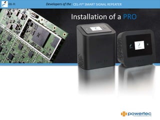
- 1. Developers of the CEL-FI® SMART SIGNAL REPEATER Installation of a PRO
- 2. Developers of the CEL-FI® SMART SIGNAL REPEATER Lets Install the PRO: • Specification • Telstra Bands, Bandwidth & Config • User Capacity • Error Codes • Tech Mode • Antennas • The 5 GHz Link • Installing Multiple Units • Testing PRO-X • Support Scenarios Agenda
- 3. Developers of the CEL-FI® SMART SIGNAL REPEATER Multi-Unit Installations There will be cases where you are required to install multiple Cel-Fi PRO’s in a building to: • Cover a larger area • Add capacity for a larger number of users • Add another operator • Extend the coverage using daisy chaining (max of two system) The Basics to Remember • Prevent feedback scenarios where CU feeds NU. • No more than two NU or CU’s next to each other (must be 1m apart) • Due to RF fluctuations try to keep CU at 70-90% gain • Use the PRO-X cable accessory in high 5GHz traffic areas • Install one system at a time getting it stable before processing to the second • Use separate external antennas to assist with feedback
- 4. Developers of the CEL-FI® SMART SIGNAL REPEATER Multi-Unit Installations Avoid feedback scenarios where CU feeds NU. The system may still work, but the coverage area will be reduced.
- 5. Developers of the CEL-FI® SMART SIGNAL REPEATER Multi-Unit Installations Up to two WU units can be next to each other but they must be separated by 1m. Also install the each system so the CU is roughly the same distance from the NU’s.
- 6. Developers of the CEL-FI® SMART SIGNAL REPEATER Multi-Unit Installations When floors are made of metal or concrete a system will be required on each level.
- 7. Developers of the CEL-FI® SMART SIGNAL REPEATER Multi-Unit Installations Multi carrier installations are less likely to result in feedback and are just required to have the boxes at least 1m apart. They may still however suffer from 5GHz issues.
- 8. Developers of the CEL-FI® SMART SIGNAL REPEATER Multi-Unit Installations Lets start with a commercial space. Remember you can’t add multiple CU’s to the one NU. The units are a married pair so you have to add a complete new system.
- 9. Developers of the CEL-FI® SMART SIGNAL REPEATER Multi-Unit Installations Start with installing a single system at one end of the building and test coverage area. This will form the basis of additional units and how many are required.
- 10. Developers of the CEL-FI® SMART SIGNAL REPEATER Multi-Unit Installations Add the second system and try to keep the distances or CU gain between each box similar to the first install. The signal from the CU’s should ideally overlap.
- 11. Developers of the CEL-FI® SMART SIGNAL REPEATER Multi-Unit Installations Place the third system using similar principles as the second. Ensure the gain on the CU is similar to the other two system.
- 12. Developers of the CEL-FI® SMART SIGNAL REPEATER Multi-Unit Installations
- 13. Developers of the CEL-FI® SMART SIGNAL REPEATER Multi-Unit Installations
- 14. Developers of the CEL-FI® SMART SIGNAL REPEATER Multi-Unit Installations
- 15. Developers of the CEL-FI® SMART SIGNAL REPEATER Multi-Unit Installations
- 16. Developers of the CEL-FI® SMART SIGNAL REPEATER Multi-Unit Installations
- 17. Developers of the CEL-FI® SMART SIGNAL REPEATER Installation of the PRO-X Cable Accessory PRO-X are passive sleaves designed for use with the PRO, enabling the connection of the network and coverage boxes using a cable. Use of the PRO-X does not turn off the 5GHz link and the required separation is still needed between the NU and CU. The cable length must not sustain >40dB of loss @ 5.8GHz. Over the next few slides we will demonstrate some test scenarios with PRO-X to help determine it’s capabilities.
- 18. Developers of the CEL-FI® SMART SIGNAL REPEATER PRO-X Cable Through Wall Setup Tests were conducted with different cables in a room where there was no mobile signal due to solid concrete walls. The purpose of the test was to check cable type and length requirements to maximise the coverage bubble. Cable Mobile Coverage Mobile Coverage Concrete Wall
- 19. Developers of the CEL-FI® SMART SIGNAL REPEATER Cable Wall Test Type/ Length CU Bars NU RSSI (dBm) CU RSSI (dBm) NU TX (dBm) CU TX (dBm) Distance Metric Coverage Distance from CU RG174 2m 1 -70 -70 6 6 -15 R: -21 4m 10m 20m 30m 40m 60m 80m 100m 120m
- 20. Developers of the CEL-FI® SMART SIGNAL REPEATER PRO-X Cable Test Setup Tests were conducted with LMR240 cable in an area where there was no mobile signal at ground level. Mobile signal was obtained by connecting a Yagi antenna to the NU. Cable Mobile Coverage Mobile Coverage
- 21. Developers of the CEL-FI® SMART SIGNAL REPEATER LMR240 Cable Test Length CU Bars NU RSSI (dBm) CU RSSI (dBm) NU TX (dBm) CU TX (dBm) Distance Metric Coverage Distance from CU 5m 1 -70 -70 6 6 -15 R: -21 4m 10m 20m 30m 40m 60m 80m 100m 120m 140m 160m 180m 200m
- 22. Developers of the CEL-FI® SMART SIGNAL REPEATER LMR400 Cable Test Length CU Bars NU RSSI (dBm) CU RSSI (dBm) NU TX (dBm) CU TX (dBm) Distance Metric Coverage Distance from CU 5m 1 -70 -70 6 6 -15 R: -21 4m 10m 20m 30m 40m 60m 80m 100m 120m 140m 160m 180m 200m
- 23. Developers of the CEL-FI® SMART SIGNAL REPEATER PRO-X Wireless Test Setup Instead of using cable to join the PRO-X sleaves, tests were conducted using two 5GHz 20dBi directional antennas. The antennas where connected to the sleaves via 75cm RG58 patch cables. The antenna link is entirely passive and does not require power. Passive Wireless Link Mobile Coverage Mobile Coverage
- 24. Developers of the CEL-FI® SMART SIGNAL REPEATER 5GHz Directional 20dBi Panel Length CU Bars NU RSSI (dBm) CU RSSI (dBm) NU TX (dBm) CU TX (dBm) Distance Metric Coverage Distance from CU 5m 1 -70 -70 6 6 -15 R: -21 4m 10m 20m 30m 40m 60m 80m 100m 120m 140m 160m 180m 200m
- 25. Developers of the CEL-FI® SMART SIGNAL REPEATER Customer Support Scenarios Issue No 4G Signal or No 4G Improvement on Handset Information to Obtain How many bars on NU and CU Check tech mode to see what bands Cel-Fi is boosting Check Handset customer is using to see what bands it supports Check signal strength on phone in test field mode with Cel-Fi turned on and off. With phone in field test mode check the channel the phone is using and also check in PRO tech mode. If using an external antenna what bands does it support Does phone connect on 4G on the outside of the building Possible Solutions Customer’s handset does not support 4G 700 - If the customer is not using an external antenna get the customer to enable the external antenna option for the 700 band using the WAVE App. This will decrease the signal by 40dB. - If the customer is using an external antenna, changing the 700 band to internal antenna and the 1800 band to external may assist. - Using an 1800 tuned antenna could also assist. - Customer’s signal is too low, recommend an external antenna
- 26. Developers of the CEL-FI® SMART SIGNAL REPEATER Customer Support Scenarios Issue No 3G Signal, No 3G Improvement on Handset or Cant Make a Call Information to Obtain How many bars on NU and CU Check tech mode to see what bands Cel-Fi is boosting Check Handset customer is using to see what bands it supports Check signal strength on phone in test field mode with Cel-Fi turned on and off. With phone in field test mode check the channel the phone is using and also check in PRO tech mode. If using an external antenna what bands does it support Does phone connect on 3G on the outside of the building Possible Solutions A 3G signal is not present at the location - Use an external antenna tuned for 850Mhz Customer is Using an iPhone - Advise customer of how iPhone’s bars measure signal differently and ask if they get better range or less dropped calls now. Customer using a GSM Phone or Does Not Support 850 band - Advise customer to upgrade phone
- 27. Developers of the CEL-FI® SMART SIGNAL REPEATER Customer Support Scenarios Issue Data Speeds Slower Through PRO Information to Obtain How many bars on NU and CU Check tech mode to see what bands Cel-Fi is boosting Check modem customer is using to see what bands it supports If using an external antenna what bands does it support Is modem connecting on 3G or 4G through Cel-Fi Check signal strength on modem with Cel-Fi turned on and off and what bands it uses. Possible Solutions If signal strength is low on the band the modem is using, connect an external antenna to the PRO Use a dedicated external antenna or MIMO antenna on 4G for the modem Ensure the modem is close to the CU
- 28. Developers of the CEL-FI® SMART SIGNAL REPEATER Further Information www.powertec.com.au www.cel-fi.com.au http://www.facebook.com/Celfirepeater This presentation can be downloaded at www.cel-fi.com.au/presentations