SlideShare a Scribd company logo
1 of 219
Download to read offline
Roughness

Characteristics
of Natural Channels

By HARRY II. BARNES, JR.
U.S. GEOLOGICAL SURVEY WATER-SUPPLY PAPER 1849
Color photographs and descriptive
data for- 50 stream channels for
which roughness coe cients have
been determined
UNITED STATES GOVERNMENT PRINTING OFFICE, WASHINGTON : 1967
Click here to return to USGS publications
DEPARTMENT OF THE INTERIOR
DONALD PAUL HODEL, Secretary
U.S. GEOLOGICAL SURVEY
Dallas L. Peck, Director
First printing 1967

Second printing 1977

Third printing 1987

For sale by the Books and Open-File Reports Section, U.S. Geological Survey,
Federal Center, Box 25425, Denver, CO 80225
�������������������
Contents
Page
Symbols____________________________________________________________________________________ vi

Abstract____________________________________________________________________________________ 1

Introduction____________________________________________________________________________ 1

Acknowledgments____________________________________________________________________ 3

Scope of report________________________________________________________________________ 3

Field investigation__________________________________________________________________ 4

Computation of reach properties
and roughness coefficients__________________________________________________ 5

Formulas__________________________________________________________________________ 5

Computation procedure________________________________________________ 7

Application of roughness coefficients____________________________________ 7

Presentation of information____________________________________________________ 8

Columbia River at Vernita, Wash . (n = 0 .024)------------ 10
Indian Fork below Atwood Dam,
near New Cumberland, Ohio. (n = 0.026)---------------- 14
Champlin Creek near Colorado City, Tex.
(n=0 .027)____________________________________________________________________ 18

Clark Fork at St . Regis, Mont. (n = 0.028)------------------ 22
Clark Fork above Missoula, Mont. (n=0 .030) ____________ 26

Columbia River at The Dalles, Oreg. (n = 0 .030) ------ 30
Esopus Creek at Coldbrook, N.Y. (n=0.030) ______________ 34

Salt Creek at Roca, Nebr. (n = 0 .030) -------------------------- 38
Blackfoot River near Ovando, Mont. (n = 0 .031)-------- 42
Coeur d'Alene River near
Prichard, Idaho (n = 0 .032) -------------------------------------- 46
Rio Chama near Chamita, N. Mex.
(n = 0.032 ; 0 .036) -------------------------------------------------------- 50
Salt River below Stewart Mountain Dam, Ariz.
(n=0 .032)____________________________________________________________________ 54

Beaver Kill at Cooks Falls, N.Y. (n=0 .033) ____________ 58

Clearwater River at Kamiah, Idaho (n=0 .033) ______ 62
��������������
Presentation of information-Continued Page
Etowah River near Dawsonville, Ga .
(n=0.041 ; 0.039 ; 0.035)-------------------------------------------- 66
West Fork Bitterroot River near Conner, Mont.
(n = 0.036) ____________________________________________________________________ 70
Yakima River at Umtanum, Wash. (n = 0 .036) __________ 74
Middle Fork Vermilion River near Danville, 111.
(n = 0.037) ____________________________________________________________________ 78
Wenatchee River at Plain, Wash . (n=0.037)______________ 82
Moyie River at Eastport, Idaho (n=0.038) ---------------- 86
Spokane River at Spokane, Wash. (n = 0.038) ------------ 90
Tobesofkee Creek near Macon, Ga.
(n=0.043 ; 0 .041 ; 0 .039) -------------------------------------------- 94
Bull Creek near Ira, Tex. (n=0.041)____________________________ 98
Middle Fork Flathead River near Essex, Mont.
(n=0.041)____________________________________________________________________ 102
Middle Oconee River near Athens, Ga .
(n=0.042 ; 0 .041 ; 0 .044) ------------------------------- ------------ 106
Beaver Creek near Newcastle, Wyo. (n =0.043) __________ 110
Catherine Creek near Union, Oreg. (n =0.043) ---------- 114
Chiwawa River near Plain, Wash . (n = 0.043)------------ 118
Esopus Creek at Coldbrook, N.Y. (n = 0 .043)-------------- 122
Grande Ronde River at La Grande, Oreg .
(n=0 .043)____________________________________________________________________ 126
Murder Creek near Monticello, Ga . (n = 0 .045) -------- 130
Provo River near Hailstone, Utah (n =0 .045 ; 0.073)__ 134
Rolling Fork near Boston, Ky. (n =0.046 ; 0 .097) ------ 138
South Beaverdam Creek near Dewy Rose, Ga.
(n=0.052 ; 0.047) -------------------------------------------------------- 142
Deep River at Ramseur, N.C. (n=0.049) ____________________ 146
Clear Creek near Golden, Colo. (n=0.050) ________________ 150
Chattahoochee River near Leaf, Ga.
(n=0.051 ; 0 .074) -------------------------------------------------------- 154
South Fork Clearwater River near Grangeville,
Idaho (n=0.051) ------------ ------------------------------------------- 158
Cache Creek near Lower Lake, Calif.
(n=0.053 ; 0 .079) -------------------------------------------------------- 162
iv
�������
Presentation of information- Continued Page
East Branch Ausable River at Au Sable Forks,
Middle Branch Wemtficld River at Goss Heights,
Mama. (n==O.O56) ---------------------------------------------------------- 170
Mission Creek near Cashmere, /m==0.0571_-- 174
HavvRiver near Bpnn1c4 N. C . [o==O.O5q).---------. 178
North Fork Cedar River near Lester, Wash .
(n = 0.059) -------------------------------------------------------------------- 182
Hominy Creek at Caod}er, N .C. /n = O .060---------------- 186
Rook Creek Canal near Dnrbn. Moot /m=0,06O-- 190
Merced River at Happy Isles Bridge, near
Yosemite, Calif. (n==O.O65)---------------------------------------- 194
Pond Creek near Louisville, Ky. /m==0 .O70---------------- 198
Boundary Creek near PortbD}, Idaho (n=0.073)------ 202
Rock Creek near D»rby' Moot. (m= 0.075) --------------- 206
Selected references------------------------------------------------------------------ 210
Index------------------------------------------.----------------------' 211
�������������
Symbols
A Area of channel cross section
C Flow-resistance factor
d Diameter of bed material
h Water-surface elevation
ha Velocity head
hf Energy loss due to boundary friction
Oh, Upstream velocity head minus the downstream velocity
head
A coefficient
K Cross section conveyance
L Length of reach
n Coefficient of roughness
Q Discharge
R Hydraulic radius
S Energy gradient
V Average velocity
�
ROUGHNESS CHARACTERISTICS

OF NATURAL CHANNELS

By Harry H. Barnes, Jr .
Abstract
Color photographs and descriptive data are presented for 50 stream
channels for which roughness coefficients have been determined .
All hydraulic computations involving flow in open channels require an
evaluation of the roughness characteristics of the channel. In the absence
of a satisfactory quantitative procedure this evaluation remains chiefly an
art. The ability to evaluate roughness coefficients must be developed
through experience. One means of gaining this experience is by examin­
ing and becoming acquainted with the appearance of some typical channels
whose roughness coefficients are known.
The photographs and data contained in this report represent a wide
range of channel conditions. Familiarity with the appearance, geometry,
and roughness characteristics of these channels will improve the engineer's
ability to select roughness coefficients for other channels .
INTRODUCTION
The principal objective of this report is to present descriptive
data and photographs for 50 different stream channels for
which roughness coefficients have been determined. This
information, which has been accumulated by the U.S . Geo­
logical Survey during the past 15 years, was previously availa­
ble only in a photographic slide library in three-dimensional
color. Numerous requests for copies of the slides from organi­
zations and private individuals led to the justification for the
present report.
All hydraulic computations involving flow in open channels
require an evaluation of the roughness characteristics of the
channel . At the present state of knowledge, the selection of
roughness coefficients for natural channels remains chiefly an
art. There are no resistance diagrams or quantitative relation­
ships available similar to those used for steady flow in uniform
pipes or for the frictional resistance of ships. Consequently the
ability to evaluate roughness coefficients for natural channels
representing a wide range of conditions must be developed
through experience.
The experience necessary for the proper selection of rough­
ness coefficients can be obtained in several ways, namely (1) to
understand the factors that affect the value of the roughness
coefficient, and thus acquire a basic knowledge of the problem,
(2) to consult a table of typical roughness coefficients for chan­
nels of various types (Woodward and Posey, 1941), and (3) to
examine and become acquainted with the appearance of some
typical channels whose roughness coefficients are known.
Photographs of channels of known resistance are thus useful
in estimating the roughness characteristics of similar channels .
The photographs and data presented in this report cover a wide
range in conditions. Familiarity with the geometry, appear­
ance, and roughness characteristics of these channels will
improve the engineer's ability to select roughness coefficients
for other channels .
To the untrained beginner, the selection of a roughness
coefficient can be no more than a guess; and different indivi­
duals obtain different results. Furthermore, it is sometimes
difficult to convince either the layman or the scientist that
consistently reliable roughness coefficients can be selected by
trained engineers on the basis of sound judgment and experi­
ence. Fortunately, even though the, selection of the coef­
ficients is classified as an art, the accuracy of many selections
can be evaluated in exact engineering or statistical terms.
The ability to evaluate the roughness characteristics of
channels is important in the hydraulic work of the U.S . Geo­
logical Survey. This ability, for example, is involved in the
�
methods (Benson and Dalrymple, 1966 ; Dalrymple and Ben­
son, 1966 ; Bodhaine, 1966 ; Matthai, 1966 ; Hulsing, 1966)
which are used in defining the peak discharge of most major
floods. For this reason the Survey maintains a program
which both trains young engineers in the evaluation of channel
roughness and tests the accuracy of roughness coefficients by
veteran engineers. The results of these tests as reported by
Bailey and Ray (1966) indicate that trained engineers can
select roughness coefficients with an accuracy of plus or minus
15 percent under most conditions. These facts prove that
present methods are sound but that there is much room for
improvement. A quantitative procedure for determining the
roughness characteristics of channels has been the goal of
research in the Survey and in other organizations for many
years, but as yet little practical success has been achieved.
ACKNOWLEDGMENTS
Data contained in this report represent contributions by
many engineers of the U .S. Geological Survey. Much credit
is due Hollister Johnson and Tate Dalrymple who conceived
and promoted the Survey's program to verify roughness
coefficients in natural channels.
The author gratefully acknowledges the advice and assist-
ance of R . W. Carter, W. R. Stokes, E. D. Cobb, and R. E .
Smith.
SCOPE OF REPORT
Information on the geometry and roughness characteristics
of 50 different stream channels is presented in the report. All
of the stream channels are considered to be stable . Sand-
channel streams were not included in the report because
roughness coefficients for streams of this type have been
defined in terms of size of bed material and other variables
(Simons and Richardson, 1962) .
The 50 sites include a wide range of hydraulic conditions
from the boulder-strewn mountain stream of the western
conterminous United States to the heavily vegetated flat-
sloped stream of the southern conterminous United States .
3
�
The techniques used in field investigations at each site are
first discussed in the report. The procedures used in comput­
ing the value of the roughness coefficient are then described.
The remainder of the report consists of the presentation of a
set of data and photographs for each of the 50 sites.
FIELD INVESTIGATION
Sites were selected for study after a major flood had occurred
in a given region. Each site met the following criteria:
1 . The peak discharge of the flood was measured by the
current-meter method, or determined from a well-defined
stage-discharge relation ;
2 . Good high-water marks were available to define the water-
surface profile at the time of the peak ;
3 . A fairly uniform reach of channel was available near the gage;
4. The flood discharge was within the channel banks-that
is, extensive flow in flood plains did not exist.
A transit-stadia survey of each reach was completed shortly
after the flood. The necessary information was obtained in
this survey to plot accurately to a common datum (1) the
water-surface profile as represented by high-water marks, (2)
a plan view of the reach, (3) cross sections at intervals along
the reach . Surveying techniques used in this investigation are
described in detail by Benson and Dalrymple (1966) .
Photographs of the. reach were taken during the time of
the survey. The photographs shown in this report thus
represent conditions in the reach immediately after the flood.
A size description of the bed material at most of the sites
was determined by sampling methods (Wolman, 1954) . These
samples were in general taken several years after the flood
for which the roughness coefficient was determined. The
samples may or may not be representative of the bed material
at the time of the peak . Frequency distributions of bed-
material size were determined by sieve analysis where the
medium size of the material was less than 50 mm and, where
the material was too large to sieve, by measuring the inter­
mediate axis of particles selected at random from the bed
surface.
4
�
COMPUTATION OF REACH PROPERTIES
AND ROUGHNESS COEFFICIENTS
Formulas
Most open-channel flow formulas can be expressed in the
following general terms,
Q=C A Rz S' (1)
where Q is the discharge, in cubic feet per second ; C is a
factor of flow resistance ; A is the cross-sectional area of the
channel, in square feet ; R is the hydraulic radius, in feet ;
and S is the energy gradient. The Manning equation, one
of the well-known variations of equation 1, was used as the
basis for computing the reach properties and roughness co­
efficients given in this report. The Manning equation is
__ 1 .486
AR2/3 5112
Q' n
where n is a roughness coefficient and other variables in the
equation are as defined above.
The Manning equation was developed for conditions of
uniform flow in which the water-surface profile and energy
gradient are parallel to the streambed, and the area, hydraulic
radius, and depth remain constant throughout the reach.
For lack of a better solution, it is assumed that the equation
is also valid for nonuniform reaches, invariably found in
natural channels, if the energy gradient is modified to reflect
only the losses due to boundary friction. The energy equation
for a reach of nonuniform channel between sections 1 and
2 in figure 1 is (see p. J)
(h+h,), = (h+hv)2+(hf)1.2+k(Ohv), .2
where
h =elevation of the water surface at the respective
sections above a common datum;
hr, = velocity head at the respective section = «V2/2g;
hf= energy loss due to boundary friction in thereach;
5
������
Ahv =upstream velocity head minus the downstream
velocity head ;
k(Ahv) = energy loss due to acceleration of velocity or
deceleration of velocity in a contracting or
expanding reach; and
k=a coefficient taken to be zero for contracting
reaches and 0.5 for expanding reaches.
In computing the values of n listed in this report the value of «,
the velocity head coefficient, was always considered to be 1 .00.
The friction slope S to be used in the Manning equation
is thus defined as
S=hy
Ah+Ah,-k(Ah,) (4)
L L
where Ah is the difference in water-surface elevation at the
two sections and L is the length of the reach.
In using the Manning equation the quantity (1 .486/n)AR2 i
3 ,
called conveyance and designated K, is computed for each
cross section. The mean conveyance in the reach between
any two sections is computed as the geometric mean of the
conveyance of the two sections . The discharge equation in
terms of conveyance is
Q= 11K2 S
where S is the friction slope as previously defined.
In this investigation the average value of the Manning n was
computed for each reach from the known discharge, the water­
surface profile, and the hydraulic properties of the reach as
defined by 2-17 cross sections. The following equation,
which is based on the same concepts and definitions as equa­
tions 2-5, was used in these computations. The equation is
applicable to a multisection reach of M cross sections which are
designated 1, 2, 3, . . . M-1, M.
1.486 (h+ha)1-(h+hv)M-[(k Ohv)1.2+(k Ohv)2.3+. . .-1­
n=
Q ~L .2 + L2.3 . . . +L(m-1).M
Z1 Z2 Z2Z3 z(M-1)ZM
(k Ahv)(M-1).M] (6)
where Z = AR21' and other quantities are as previously defined.
6
������
Computation Procedure

A planimetric map of each reach was developed by plotting
from the notes of the field survey. The location of all high
water marks and cross sections was shown on the map. The
distances between cross sections were determined from the map.
The profile of the water surface through the reach was
developed separately along each bank by plotting the elevation
and stationing of high-water marks. The water-surface ele­
vation at each cross section was determined as the average of
the water-surface elevation on each bank as taken from the
water-surface profiles.
Cross sections were plotted from the field notes, and data on
stationing, distance, ground elevations, depths, and top widths
were tabulated. The area and wetted perimeter for each
panel between given ground elevations were computed. The
area, wetted perimeter, and hydraulic radius for each cross
section were determined, and values of AR"' were computed.
The average value of n for each reach was then determined
by substituting the proper quantities in equation 6.
The computation procedure is virtually the same as for com­
putation of discharge by the slope-area method . This pro­
cedure is described in detail by Dalrymple and Benson (1966) .
APPLICATION OF ROUGHNESS
COEFFICIENTS
The values of n presented in the report are intended for use
in the Manning equation
V _ 1 .486 R2/3 5112
(English units)
n
R2/3 S112
or V (metric units)
n
The value of n may be converted to values of the Chezy Cby
the relation
= 1 .486 R116
C (English units)
n
and the value of C may then be used in the Chezy equation
V=CRS
��
All these equations are limited to turbulent flow in fully
rough channels. Flow in natural channels normally meets
this criterion.
PRESENTATION OF INFORMATION
A four-page set consisting of channel data, plan sketches
(not to scale) and cross sections, and photographs, is presented
for each reach in the following section of the report. Each
set of data is identified by the permanent gaging-station
number and name used by the U.S. Geological Survey in
publication of streamflow-records .
The data tabulation shows the location of the gage and a
reference cross section, the drainage area of the stream, the
date of the flood, the peak gage height at the gage and at sec­
tion 1 during the flood, the peak discharge measured by cur-
rent-meter method, the computed roughness coefficient for the
reach, a general description of the channel, the median bed-
material size, d o, and the reference size for which 84 percent
of the bed material is finer, d84. The area, top width, mean
depth (area/top width), hydraulic radius, and mean velocity
corresponding to the water-surface elevation at the time of the
peak are listed for each cross section. The distance or length
between cross sections and the fall in water surface between
cross sections are also shown. Information for two or more
peak discharges is available at some sites. These data are
listed according to the magnitude of discharge. Data cor­
responding to the largest discharge appear first.
At several sites a small percentage of the flow occurred in
the shallow flood plain adjacent to the main channel. For
each of these sites the data and computations reflect the flow
of the main channel .
Data for the site, Rolling Fork at Boston, Ky., are unique in
that roughness coefficients were computed for both the over­
flow plain and the main channel.
Two color photographs taken immediately after the flood
are shown for each reach . The position of the camera and the
���
number of the picture are shown on the plan sketch by a
pointer, which shows the direction in which the camera was
pointed. The water level at the time of the peak is indicated
in some of the photographs by a horizontal rod or tape.
The initial station for cross sections is at the left bank. Plots
are arranged so that the left bank appears on the reader's left.
The water levels shown on the cross sections correspond to the
water-surface profile at the time of the peak as defined by
high-water marks.
Sites are arranged according to the value of the computed
roughness coefficient, in ascending order.
i
"*-Section 1 -1. Section 2,,rj.
v
t
PLAN VIEW
hvl I 1 ~ ---- - E rgy gradient Ihf+k(Ah)
Water surface
[hv2
Datum
L
PROFILE VIEW
Figure 1. -Definition sketch of a slope-area reach.
����
n = 0.024
12-4645. Columbia River at Vernita,Wash.
Gage location.-In sec. 11, T. 13 N., R. 24 E., at the Richmond
ferry site, 0.5 mile north of Vernita station. Gage presently
operated 50 miles upstream for station called Columbia
River at Trinidad, Wash. Section 1 is 5,000 ft upstream
from cableway at Vernita gage.
Drainage area.-89,700 sq mi, approximately.
Date offlood.-May 22, 1949 .
Gage height.-48 .33 ft at Trinidad gage ; 29 .5 ft (different
datum) at section 1 .
Peak discharge.-406,000 cfs.
Computed roughness coefficient. -Manning n=0.024.
Description of channel.-Bed consists of slime-covered cobbles
and gravel . The straight and steep left bank is composed
of cemented cobbles and gravel. The gently sloping right
bank consists of cobbles set in gra;-e1 and is free of vegetation.
Reach properties
Section Area
(sq ft)
Top
width
(ft)
Mean
depth
(ft)
Hydraulic
radius
(ft)
Mean
velocity
(ft per sec)
Length (ft)
between
sections
Fall (ft)
between
sections
1 . . . . . . . . . . .
2 . . . . . . . . . . .
3 . . . . . . . . . . .
47,100
49,000
49,600
1,800
1,650
1,760
26.2
29 .7
28.2
26 .16
29,56
28.10
8.65
8.28
8.17
. . . . . . . . . . . .
2,500
2,500
. . . .
0.48
.49
Notes.-
n = 0.024
CROSS SECTIONS
Plan sketch and cross sections, Columbia River at
Vernita, Wash.
n = 0.024
No. 67 upstream from top of bank at section 3,
Columbia River at Vernita, Wash.
1 2
n = 0.024
No . 66 upstream along right bank from section 3,
Columbia River at Vernita, Wash .
1 3
�
n = 0.026
3-1215. Indian Fork belowAtwood Dam, near
NewCumberland, Ohio
Gage location.-Lat 40°31'30, long 81°17'20, in SEY4 sec. 28,
T. 15 N., R. 7 W., on left bank 500 ft downstream from
Atwood Dam, 0 .5 mile upstream from mouth, and 1 .5 miles
southeast of New Cumberland, Tuscarawas County. Sec­
tion 1 is about 300 ft downstream from gage.
Drainage area.-70 .3 sq mi.
Date offood.-May 11, 1948.
Gage height.-10.27 ft at gage ; 9.99 ft at section 1 .
Peak discharge.-768 cfs.
Computed roughness coefficient. -Manning n=0.026 .
Description of channel.-Bed and banks are composed of clay.
Banks are clear except for short grass and exposed tree roots
in some places.
Reach Properties
Top Mean Hydraulic Mean Length (ft) Fall (ft)
Section I Area width depth radius velocity between between
(sq ft) (ft) (ft) (ft) (ft per sec) sections
. sections
1 . . . . . . . . . . . 280 52 5.4 4.87 2.74 . . . . . . . . . . . . . , . .
2 . . . . . . . . . . . 273 51 5.4 4.82 2.82 257 0.08
3 . . . . . . . . . . . 279 52 5.4 4.97 2.76 202 .05
Notes.-
n = 0.026
CROSS SECTIONS
12
10
8
6
4
2
10
8
6
4
2
10
8
6
4
2
0 10 20 30 40 50 60
WIDTH, IN FEET
Plan sketch and cross sections, Indian Fork below
Atwood Dam, near New Cumberland, Ohio.
1 5
n = 0.026
No. 327 upstream from right bank below section 3,
Indian Fork belowAtwood Dam, near New Cumberland, Ohio.
16
n = 0.026
No. 329 upstream from right bank at section 2,
Indian Fork belowAtwood Dam, near New Cumberland, Ohio.
17
�
n = 0.027
8-1235 . Champlin Creek near Colorado City, Tex.
Gage location.-Lat 32°19', long 100°49', on right bank 600 ft
downstream from South Fork, 5 miles southeast of Colorado
City, Mitchell County, and 5 .5 miles upstream from mouth .
Section 2 is 350 ft downstream from gage.
Drainage area.-158 sq mi .
Date offood.-May 17, 1949 .
Gage height.-5 .05 ft at gage; 4 .24 ft at section 2 .
Peak discharge.-2,390 cfs.
Computed roughness coefficient. -Manning n=0.027 .
Description of channel.-Bed consists of gravel deposits over
smooth to rough rock. Banks are covered with grass and
have a few outcrops .
Reach properties
Section Area
(sq ft)
Top
width
(ft)
Mean
depth
(ft)
Hydraulic
radius
(ft)
Mean
velocity
(ft per s°_ 7)
Length (ft)
between
sections
Fall (ft)
between
sections
2 . . . . . . . . . . . 412 85 4.8 4.71 5.80 . . . . . . . . . . . . . . . .
3 . . . . . . . . . . . 344 79 4.4 4.20 6.96 176 0.43
4 . . . . . . . . . . . 307 70 4.4 4.24 7.78 148 .71
Notes.-
n = 0.027
CROSS SECTIONS
a0
W
a
H
W
W
Z
Z
_Z
0
J
W
Plan sketch and cross sections, Champlin Creek near
Colorado City, Tex.
1 9
n = 0.027
No. 511 downstream along right bank from above section 2,
Champlin Creek near Colorado City, Tex.
20
n = 0.027
No. 512 upstream along left bank from below section 4,
Champlin Creek near Colorado City, Tex.
2 1
�
n = 0.028
12-3 545 . Clark Fork at St. Regis, Mont.

Gage location.-Lat 47° 18'05, long 115° 05'15, in center of
SW Y4 sec. 19, T. 18 N., R. 27 W., on left bank at St. Regis,
0.5 mile downstream from St. Regis River. Section 1 is
660 ft upstream from gage.
Drainage area.-10,709 sq mi .
Date offlood.-May 24, 1948 .
Gage height.-19 .96 ft at gage ; 20.42 ft at section 1 .
Peak discharge.-68,900 cfs.
Computed roughness coefficient.-Manning n = 0.028 .
Description of channel.-Bed consists of well-rounded boulders;
d5o =135 mm, d84 = 205 mm. Banks are composed of gravel
and boulders, and have tree and brush cover.
Reach properties
Top Mean Hydraulic Mean Length (ft) Fall (ft)
Section Area width depth radius velocity between between
(sq ft) (ft) (ft) (ft) (ft per sec) sections sections
1 . . . . . . . . . . . 6,860 404 16.98 16.70 10.04 . . . . . . . . . . . . . . . .
2 . . . . . . . . . . . 6,976 429 16.26 16.04 9.88 755 0.555
3 . . . . . . . . . . . 7,194 454 15.85 15.64 9.58 438 .32
Notes.-
n = 0.028
CROSS SECTIONS
a
0
W
a 20
H
W
W
W
10
Z
Z
F­
a
W
J
W
Plan sketch and cross sections, Clark Fork at St. Regis, Mont.
23
n = 0.028
No. 22 downstream along right bank from section 2,
Clark Fork at St. Regis, Mont.
24
n = 0.028
No. 23 upstream along left bank from section 2,
Clark Fork at St. Regis, Mont.
25
n = 0.030
12-3405 . Clark Fork above Missoula, Mont.
Gage location.-Lat 46°52'40, long 113°55'40, in NWY4NWj
sec . 19, T . 13 N, R. 18 W., on right bank 3 miles down-
stream from Blackfoot River and 3 miles east of Missoula .
Section 1 is 405 ft upstream from gage.
Drainage area.-5,999 sq mi .
Date offlood.-May 23, 1948 .
Gage height.-13 .07 ft at gage ; 14 .54 ft at section 1 .
Peak discharge.-31,500 cfs .
Computed roughness coefficient. -Manning n = 0.030.
Description of channel.-Bed is composed of sand, gravel, and
boulders ; d5o =175 mm, d84 = 325 mm. Thick undergrowth
is along right bank and along the left bank in the lower
part of the reach.
Reach Properties
Section Area
(sq ft)
Top
width
(ft)
Mean
depth
(ft)
Hydraulic
radius
(ft)
Mean
velocity
(ft per sec)
Length (ft)
between
sections
Fall (ft)
between
sections
1 . . . .
2 . . . .
3 . . . .
4 . . . .
.
.
.
.
. . . . . .
. . . . . .
. . . . . .
. . . . . .
3,866
3,461
3,634
3,798
285
267
294
312
13.56
12.96
12.36
12.17
13.24
12.64
12.10
11 .95
8.15
9.10
8.67
8.29
. . . . . . . .
305
243
297
. . . . . . . .
0.63
.25
.18
Notes. -
��
n = 0.030
a
0
W
a
0
W
W
z
z
0
a
W
J
W
PLAN SKETCH
2 /1 3 4
Gage
I
2
CROSS SECTIONS
WIDTH, IN FEET
Plan sketch and cross sections, Clark Fork above
Missoula, Mont.
27
n = 0.030
No. 18 downstream along left bank from above section 3,
Clark Fork above Missoula, Mont.
28
n = 0.030
No. 19 downstream through reach from bridge 400 ft above
section 1, Clark Fork above Missoula, Mont.
29
n = 0.030
14-1057 . Columbia River at The Dalles, Oreg.
Gage location .-Lat 45°36'10, long 121°10'40, in NWY4 sec. 3,
T. 1 N., R. 13 E., at upstream end of Port of The Dalles
dock at The Dalles, 3 .2 miles downstream from The Dalles
Dam and at mile 189 .3 . Section 4 is at cableway 9 miles
upstream from gage .
Drainage area .-237,000 sq mi, approximately.
Date offlood.-May 31, 1948 .
Gage height .-154 .56 ft at gage ; 171 .44 ft at section 1 .
Peak discharge .-1,000,000 cfs .
Computed roughness coefficient.-Manning n = 0 .030.
Description of channel.-Left bank consists of sand, gravel, and
boulders, and has light cover of brush in some places .
Right bank is formed by severely scalloped basalt cliffs .
The bed material is fairly well graded from 18-inch boulders
along the left bank down to sand at the base of the right
bank.
Reach Properties
Section Area
(sq ft)
Top
width
(ft)
Mean
depth
(ft)
Hydraulic
radius
(ft)
Mean
velocity
(ft per sec)
Length (ft)
between
sections
Fall (ft)
between
sections
1 . . . . . . . . . . . 94,650 1,980 47 .80 47 .28 10.57 . . . . . . . . . . . . . .
2 . . . . . . . . . . . 90,810 1,640 55.37 54.10 11 .01 2,003 . 0.50
3 . . . . . . . . . . . 89,040 1,485 59.96 57.80 11 .23 778 .20
4 . . . . . . . . . . . 91,890 1,600 57.43 55 .81 10.88 1,394 .41
Notes.-
n = 0.030
CROSS SECTIONS
250
200
Water surface 5/31/48 I I i I
150
1
100
200
150
100
* Properties of overflow sections
not included in table
200
I
150
3
100
50
200
150
I4
100
50
0 500 1000 1500 2000 2500 3000 3500
WIDTH, IN FEET
Plan sketch and cross sections, Columbia River at
The Dalles, Oreg.
31
No. 47 downstream along right bank from above section 1,
Columbia River at The Dalles, Oreg.
32
n = 0.030
No. 38 upstream along left bank from section 4,
Columbia River at The Dalles, Oreg.
33
�
n = 0.030
1--362 5 . Esopus Creekat Coldbrook, N.Y.
Gage location .-Lat 42°00'45, long 76°16'10, on left bank at
downstream side of highway bridge at Coldbrook, Ulster
County, 1 .5 miles upstream from Ashokan Reservoir and
2.5 miles south of Mount Tremper. Section 1 is about 400
ft upstream from Highway 28-A, which is about 6 miles
southeast of gage .
Drainage area.-192 sq mi.
Date offood.-Mar . 22, 1948.
Gage height.-12.39 ft at gage; 15 .60 ft (different datum) at
section 1 .
Peak discharge.-13,900 cfs.
Computed roughness coefficient.-Manning n=0 .030.
Description of channel.-The bed is coarse gravel and both banks
are lined with trees and brush.
Reach Properties
Section Area
(sq ft)
Top
width
(ft)
Mean
depth
(ft)
Hydraulic
radius
(ft)
Mean
velocity
(ft per sec)
Length (ft)
between
sections
Fall (ft)
between
sections
1 . . . . . . . .
2 . . . . . . . .
.
.
. .
. .
1,600
1,589
301
284
5.3
5.6
5.28
5.54
8.70
8.77
. . . . . . . . . . . . . . . .
471 1 .60
Notes . -
PLAN SKETCH
2
CROSS SECTIONS
a
0
a
m
a
W
W
W
Z
Z
H
a
W
J
W
Plan sketch and cross sections, Esopus Creek at
Coldbrook, N.Y.
35
n = 0.030
No. 354 upstream along left bank from section 2,
Esopus Creek at Coldbrook, N.Y.
36
n = 0.030
No. 357 upstream from right end of bridge below reach,
Esopus Creek at Coldbrook, N.Y. (at Highway 28-A) .
37
��
n = 0.030
6-8030. Salt Creek at Roca, Nebr.

Gage location.-Lat 40°39'33, long 96°39'39, in SWY4 sec.
17, T . 8 N., R . 7 E., on left bank 15 ft downstream from
highway bridge at west edge of Roca . Section 1 is 75 ft
downstream from gage .
Drainage area.-174 sq mi.
Date offood.-May 2, 1954.
Gage height.-16 .02 ft at gage ; 15 .94 ft at section 1 .
Peak discharge.-1,860 cfs.
Computed roughness coefficient. -Manning n = 0.030.
Description of channel.-Bed consists of sand and clay. Banks
are generally smooth and are free of vegetal growth during
floods.
Reach properties
Section Area
(sq ft)
Top
width
(ft)
Mean
depth
(ft)
Hydraulic
radius
(ft)
Mean
velocity
(ft per sec)
Length (ft)
between
sections
Fall (ft)
between
sections
1 . . . . . . . . . . . 528 72 7.4 6.7 3.46 . . . . . . . . . . . . . . . .
2 . . . . . . . . . . . 502 80 6.3 5.9 3.71 113 0.09
3 . . . . . . . . . . . 497 69 7.2 6.6 3.74 110 .06
4 . . . . . . . . . . . 497 78 6.4 5.9 3.74 134 .05
Notes.-
n = 0.030
825
4
CROSS SECTIONS
a
0
W
a
W
W
W
Z
Z
H
a
W
J
W
Plan sketch and cross sections, Salt Creek at Roca, Nebr.
39
n = 0.030
No. 824 downstream from above section 1,
Salt Creek at Roca, Nebr.
40
n = 0.030
No. 825 downstream from below section 2,
Salt Creek at Roca, Nebr .
41
�
n = 0.031
12-3385. Blackfoot River near Ovando, Mont.
Gage location.-Lat 47°01'10, long 113 ° 13'40, in SEY4NWY4
sec. 34, T. 15 N., R. 13 W., . on left bank 0.25 mile upstream
from Monture Creek and 5 miles west of Ovando. Section
1 is about 0.25 mile upstream from gage .
Drainage area.-1,274 sq mi.
Date offood.-May 22, 1948 .
Gage height .-6 .84 ft at gage ; 16.34 ft at section 1 .
Peak discharge.-8,200 cfs .
Computed roughness coefficient .-Manning n = 0 .031 .
Description of channel.-Bed is gravel and boulders ; d5o = 155
mm, d84 = 280 mm. Banks consist of same material and
are relatively free of vegetation .
Reach properties
Top Mean Hydraulic Mean Length (ft) Fall (ft)
Section Area width depth radius velocity between between
(sq ft) (ft) (ft) aft) (ft per sec) sections sections
1 . . . . . . . . . . . 1,230 199 6.18 6.12 6.67 . . . . . . . . . . . . . .
2 . . . . . . . . . . . 1,140 189 6.03 5,97 7.19 292 0.68
Notes.-
n = 0.031
PLAN SKETCH
2
CROSS SECTIONS
18
16
14
12
Q
10
W
Q
8
W
W
W
Z
Z
16
Q
wJ
w 14
12
10
40 80 120 160 200
WIDTH, IN FEET
Plan sketch and cross sections, Blackfoot River near
Ovando, Mont.
43
n = 0.031
No . 1 downstream from left bank above section 1,
Blackfoot River near Ovanda, Mont.
44
n = 0.031
No. 3 upstream towards right bank from below section 2,
Blackfoot River near Ovanda, Mont.
45
�
n = 0.032
12-4120. Coeur d'Alene River near Prichard,
Idaho
Gage location .-Lat 47°38'05, long 115°58'55, in lot 7, sec. 32,
T. 50 N., R. 4 E., on right bank 0.2 mile downstream from
Beaver Creek and 1 .75 miles southwest of Prichard. Sec­
tion 1 is 570 ft upstream from gage .
Drainage area .-583 sq mi.
Date offood.-May 21, 1948 .
Gage height.-9 .24 ft at gage; 10.98 ft at section 1 .
Peak discharge.-11,300 cfs.
Computed roughness coefficient.-Manning n = 0 .032.
Description of channel.-Bed is composed of rock along left edge,
gravel and small boulders elsewhere ; dso =103 mm, d8, =
650 mm. Left bank is irregular bedrock, steep and clean.
Right bank consists of sand and gravel covered with heavy
growth of brush and trees.
Reach properties
Section Area
(sq ft)
Top
width
(ft)
Mean
depth
(ft)
Hydraulic
radius
(ft)
Mean
velocity
(ft per sec)
Length (ft)
between
sections
Fall (ft)
between
sections
1 . . . . . . . . . . .
2 . . . . . . . . . . .
3 . . . . . . . . . . .
4 . . . . . . . . . . .
1,260
1,200
1,306
1,312
162
141
159
185
7 .8
8.5
8.2
7.1
7 .65
8.00
7.96
6.87
8.97
9.42
8.65
8.61
. . . . . . . .
230
400
302
. . . . . . . .
0.50
.88
.92
Notes.-
0
n = 0.032
PLAN SKETCH
3
CROSS SECTIONS
W

H
W
WU­
Z

WJ
W
Plan sketch and cross sections, Coeur d'Alene River near
Prichard, Idaho.
47
n = 0.032
No. 34 downstream through reach from right bank,
Coeur d'Alene River near Prichard, Idaho.
48
n = 0.032
No. 36 downstream along right bank at section 1,
Coeur d'Alene River near Pritchard, Idaho.
49
�
n = 0.032; 0.036
8-2900. Rio Chama near Chamita, N. Mex.
Gage location .-Lat 36°04'25, long 106°06'39, in NEY4NEj
sec . 8, T. 21 N ., R . 8 E., on left bank 200 ft downstream
from bridge on U.S . Highway 285, 0 .5 mile west of Chamita,
2.5 miles northwest of San Juan Pueblo, and 3 miles
upstream from mouth. Section 1 is about 200 ft upstream
from gage.
Drainage area.-3,140 sq mi .
Date offlood.-Mar. 24, 1950 ; Apr. 3, 1950 .
Gage height.-3.41 ft, 2 .95 ft at gage ; 3 .65 ft, 3 .18 ft at section 1 .
Peak discharge.-1,060 cfs ; 684 cfs.
Computed roughness coefficient. -Manning n=0.032 ; 0.036 .
Description of channel.-The bed consists of sand and gravel .
The left bank is rock and the right bank is mostly gravel .
Reach Properties
Section Area
(sq ft)
Top
width
(ft)
Mean
depth
(ft)
Hydraulic
radius
(ft)
Mcan
velocity
(ft per sec)
Length (ft)
between
sections
Fall (ft)
between
sections
Mar . 24, 1950
1 . . . . . . . . . . .
2 . . . . . . . . . . .
312
297
95
84
3 .3
3 .5
3 .12
3 .45
3 .40
3 .57 202 .
. . . .
0
.24
Apr. 3, 1950
1 . . . . . . . . . . . 235 92 2.6 2 .52 2.91
2 . . . . . . . . . . . 249 81 3.1 2 .95 2.75 . . . . 202 . . . .'0.23
Notes .­
n = 0.032; 0.036
PLAN SKETCH
CROSS SECTIONS
6
2
Q
H
w
ww
20 40 60 80 100 120
Z
Z 4
O I
i
Q 2
J
w
w
0
20 40 60 80 100 120
WIDTH, IN FEET
Plan sketch and cross sections, Rio Chaina
near Chamita, New Mex.
5 1
n = 0.032; 0.038
No. 547 upstream along right bank from below section 2,
Rio Chama near Chamita, N. Mex.
52
= 0 0550 downstream from bank at section Rio ChamaN MexrightChamita, 1,
n .032; .036
No.
near . .
53
n = 0.032
9-5020. Salt River below Stewart Mountain Dam,
Ariz .
Gage location .-Lat 33°33'00, long 111'34'31, in NY2NWY4
sec. 6, T. 2 N., R. 8 E. (unsurveyed), on left bank 3.5 miles
downstream from Stewart Mountain Dam and 6 miles
upstream from Verde River. Section 1 is about 2.25 miles
downstream from gage .
Drainage area.-6,230 sq mi, of which 21 sq mi is below Stewart
Mountain Dam.
Date offood.-Mar. 24, 1950 .
Gage height .-4.26 ft at gage ; 99 .26 ft (different datum) at
section 1 .
Peak discharge.-1,280 cfs.
Computed roughness coefficient.-Manning n = 0.032 .
Description of channel .-Bed and banks consist of smooth cobbles
4 to 10 inches in diameter, average diameter about 6 inches.
A few boulders are as much as 18 inches in diameter .
Reach properties
Section Area
(sq ft)
Top
width
(ft)
Mean
depth
(ft)
Hydraulic
radius
(ft)
Mean
velocity
(ft per sec)
Length (ft)
between
sections
Fall (ft)
between
sections
1 . . . . . . . . . . . 484 189 2.6 2.55 2.65 . . . . . . . . . . . . . . . .
2 . . . . . . . . . . . 408 192 2.1 2.12 3.14 258 0.37
3 . . . . . . . . . . . 384 154 2.6 2.49 3.34 317 .50
4 . . . . . . . . . . . 449 194 2.3 2.30 2.86 294 .31
5 . . . . . . . . . . . 420 204 2.1 2.06 3.05 370 .63
6 . . . . . . . . . . . 381 207 1 .8 1 .84 3.36 333 .72
7 . . . . . . . . . . . 308 191 1 .6 1 .61 4.16 314 1 .06
Notes.-
n = 0 .032
Q
oc
Q
GC
H
mOC
Q
w
ww
Z
Z
O
Q
wJ
W
WIDTH,IN FEET
Plan sketch and cross sections, Salt River below Stewart
Mountain Dam, Ariz .
55
n = 0.032
low
No. 817 upstream along left bank from below section 6

Salt River below Stewart Mountain Dam, Ariz.
56
n = 0.032
No. 818 downstream along left bank from section 2, Salt
River below Stewart Mountain Dam, Ariz.
57
��
n = 0.033
1-4205 . Beaver Kill at Cooks Falls, N.Y.
Gage location.-Lat 41'56'50, long 74°58'45, on left bank 125
ft downstream from highway bridge in Cooks Falls, Dela­
ware County, and 5.5 miles downstream from Willowemoc
Creek. Section 5 is about 2,700 ft downstream from gage.
Drainage area .-241 sq mi .
Date offood.-Mar . 22, 1948.
Gage height.-11 .69 ft at gage ; 42.65 ft (different datum) at
section 5 .
Peak; discharge.-15,500 cfs.
Computed roughness coefficient . -Manning n=0 .033 .
Description of channel.-Bed consists of coarse gravel and cobbles
with scattered boulders. Light brush is on both banks and
some trees are near water's edge on right bank .
Reach properties
Section Area
(sq ft)
Top
width
(ft)
Mean
depth
(ft)
Hydraulic
radius
(ft)
Mean
velocity
(ft per sec)
Length (ft)
between
sections
Fall (ft)
between
sections
5 . . . . . . . . . . .
6 . . . . . . . . . . .
7 . . . . . . . . . . .
1,700
1,660
1,590
244
221
206
7.0
7.5
7.7
6 .85
7.36
7.59
9 .11
9 .33
9 .72
. . . . . . .
279
283
. . . . . . .
0.65
1 .25
Notes.-
n = 0.033
PLAN SKETCH
5 6

I

I

6 7

CROSS SECTIONS
48

44

40

36

Q 32
O
Q 44

m
Q
40

w
w 36
w
Z
32

Z
O
Q 44

wJ
w 40

36

32

30

0 50 100 150 200 250 300

WIDTH, IN FEET
Plan sketch and cross sections, Beaver Kill at Cooks Falls, N.Y.
59
n = 0.033
No. 366 upstream toward right bank from section 7, Beaver
Kill at Cooks Falls, N.Y.
60
n = 0.033
No . 367 upstream along left bank from section 7, Beaver Kill
at Cooks Falls, N.Y.
61
�
n = 0.033
13-3390. Clearwater River at Kamiah, Idaho
Gage location .-Lat 46°14', long 116°01', in sec. 1, T. 33 N.,
R . 3 E., on left bank 0.25 mile downstream from highway
bridge at Kamiah, 0.75 mile downstream from Lawyer
Creek, and 6 miles downstream from South Fork. Section
1 is about 5 .8 miles downstream from gage.
Drainage area.-4,850 sq mi, approximately .
Date offood.-May 29, 1948 .
Gage height.-19 .22 ft at gage; 46 .17 ft at section 1 .
Peak discharge.-99,000 cfs.
Computed roughness coefficient.-Manning n = 0.033 .
Description of channel.-Bed is composed of gravel and boulders
with some exposed bedrock. Channel is bordered by rail­
road on the right and highway on the left. Banks are
gravel and rock and have light vegetation cover.
Reach Properties
Section Area
(sq ft)
Top
width
(ft)
Mean
depth
(ft)
Hydraulic
radius
(ft)
Mean
velocity
(ft per sec)
Length (ft)
between
sections
Fall (ft)
between
sections
1 . . . . . . . . . . .
2 . . . . . . . . . . .
3 . . . . . . . . . . .
11,100
11,603
10,937
562
593
538
19.25
19 .58
20.32
19.45
19 .34
20.04
8.92
8.53
9.05
. . . . . . .
.732
560
. . .
. . . . .
0.35
.67
Notes.-
0
n = 0.033
CROSS SECTIONS
a
r
a
m
a
W
w
z
z
O
a
wJ
LL/
Plan sketch and cross sections, Clearwater River at
Kamiah, Idaho .
63
= 0 29 downstream left bank from above sectionRiver at Idahoalong Kamiah, 1,
n .033
No.
Clearwater .
64
n = 0.033
No. 32 upstream from left bank at section 3. Clearwater River
at Kamiah, Idaho.
65
��������
n = 0.041; 0.039; 0.035
2-3890. Etowah River near Dawsonville, Ga.
Gage location .-Lat 34°23', long 84°04', on left bank 0.5 mile
upstream from Palmer Creek, 1 mile downstream from
Russell Creek, 4 miles southeast of Dawsonville, Dawson
County, and 7 .5 miles upstream from Shoal Creek . Section
7 is 477 ft downstream from gage.
Drainage area .-103 sq mi .
Date of food.-Jan . 22, Feb . 13, Feb. 14, 1959 .
Gage height.-9.45 ft, 7 .95 ft, 2 .85 ft at gage ; 9 .02 ft, 7 .55 ft,
2 .18 ft at section 7 .
Peak discharge.-2,260 cfs ; 1,850 cfs ; 515 cfs.
Computed roughness coefficient.-Manning n = 0 .041 ; 0 .039 ; 0 .035 .
Description of channel.-Bed is sand and gravel with several
fallen trees in the reach. Banks are lined with overhanging
trees and underbrush.
Reach Properties
Section Area
(sq ft)
Top
width
(ft)
Mean
depth
(ft)
Hydraulic I Mean ~ Length (ft)
radius velocity between
(ft) (ft per sec) sections
Fall (ft)
between
sections
Jan.22, 1959
7 . . . . . . . . . . . 618 60 10.3 8 .15 3.66 . . . . . . . . . . . .
8 . . . . . . . . . . . 621 66 9 .4 7 .77 3.64 .316 . 220
9 . . . . . . . . . . . 619 63 9 .8 8 .18 3.65 286 18
10 . . . . . . . . . . 610 63 9.7 7 .77 3.70 293 14
11 . . . . . . . . . . 622 66 9.4 7 .89 3.63 203 17
Feb. 13, 1959
7 . . . . . . . . . . . 528 57 9 .3 7.37 3.50 . . . . . . . . . . . . . .
8 . . . . . . . . . . . 531 64 8 .3 6.95 3.48 316 . . 0.19
9 . . . . . . . . . . . 532 59 9 .0 7 .56 3.48 286 .20
10 . . . . . . . . . . 525 61 8 .6 7.00 3.52 293 .14
11 . . . . . . . . . . 530 62 8 .6 7.10 3.49 203 .14
Feb. 14, 1959
7 . . . . . . . . . . . 240 51 4.7 4.04 2.15 . . . . . . . . . . . . . . . .
8 . . . . . . . . . . . 209 59 3.5 3 .27 2.46 316 0.16
9 . . . . . . . . . . .
10 . . . . . . . . . .
235
203
53
59
4.4
3.4 I
4.04
3 .19
2.19
2.54
286
293
.17
.19
11 . . . . . . . . . . 219 55 4.0 3 .59 2.35 203 .15
Notes.-
66
Gage n = 0.041; 0.039; 0.035
f-
Q
0
W
Q
H
W
W
U­
Z
Z
H
Q
1W
J
W
Plan sketch and cross sections, Etowah River
near Dawsonville, Ga.
67
n = 0.041; 0.039; 0.035
No. 1167 downstream from right bank above section 9, Etowah
River near Dawsonville, Ga.
68
n = 0.041; 0.039; 0.035
No. 1168 upstream from right bank at section 11, Etowah
River near Dawsonville, Ga.
69
���
n = 0.036
12-34-25 . West Fork Bitterroot River near
Conner, Mont.
Gage location .-Lat 45°44', long 114°17', in NEY4NWj sec.
26, T. 1 S., R. 22 W ., on right bank 0 .5 mile downstream
from Painted Rocks Lake, 6 miles upstream from Nez Perce
Creek, and 16 miles southwest of Conner. Section 1 is about
600 ft downstream from gage .
Drainage area .-317 sq mi.
Date of,food. -May 29, 1948.
Gage height,.-6 .08 ft at gage ; 3 .27 ft at section 1 .
Peak discharge.-3,880 efs.
Computed roughness coefficient. -Manning n = 0.036 .
Description of channel.-Bed is gravel and boulders; d o =172
Min, d14 = 265 mm . The left bank is lined with overhanging
bushes. The right bank is lined with trees.
Reach Properties
Section Area
(sq ft)
Top
width
(ft)
Mean
depth
(ft)
Hydraulic
radius
(ft)
Mean
velocity
(ft per sec)
Length (ft)
between
sections
Fall (ft)
between
sections
1 . . . . . . . . . . .
2 . . . . . . . . . . .
3 . . . . . . . . . . .
504
494
516
107
105
103
4.7
4.7
5.0
4.62
4.57
4.82
7.70
7.85
7.52
. . . . . . .
222 .
302
.
. . . . . . .
1 .02
1 .40
Notes.-
������
0
n = 0.036
CROSS SECTIONS
a
W
a
W
W
Z
Z
H
a
W
W
0 20 40 60 80 100 120
WIDTH,IN FEET
Plan sketch and cross sections, West Fork Bitterroot River
near Conner, Mont.
71
n = 0.036
No. 175 downstream from section 1, West Fork Bitterroot
River near Conner, Mont.
72
n = 0.036
No. 177 downstream from right bank above section 1, West
Fork Bitterroot River near Conner, Mont.
73
�
n = 0.036
12-4845 . Yakima River at Umtanum, Wash.
Gage location .-Lat 46°51'45, long 120°28'30, in NWY4 sec.
20, T. 16 N., R . 19 E., on right bank at Umtanum, 0 .5 mile
upstream from Umtanum Creek and 10 miles south of
Ellensburg. Section 1 is about 650 ft upstream from gage.
Drainage area .-1,590 sq mi, approximately.
Date offood.-May 29, 1948 .
Gage height.-38.98 ft at gage ; 41 .27 ft at section 1 .
Peak discharge.-27,700 cfs.
Computed roughness coefficient.-Manning n = 0 .036.
Description of channel.-Bed consists of gravel and boulders.
Left bank is rock riprap with bushes. Right bank is
mildly sloped and has some boulders, brush, and weed cover.
Reach Properties
Top Mean Hydraulic Mean Length (ft) Fall (ft)
Section Area width depth radius velocity between between
(sq ft) (ft) (ft) (ft) (ft per sec) sections sections
1 . . . . . . . . . . . 2,680 222 12 .1 11 .62 10.34 . . . . . . . . . . . . . . . .
2 . . . . . . . . . . . 2,550 208 12 .3 11 .61 10.86 324 0.99
3 . . . . . . . . . . . 2,490 232 10 .7 10.32 11 .12 302 .86
Notes.-
PLAN SKETCH
2
CROSS SECTIONS
50
Water surface 5/1 /56
40
1
30
* Prloperties of
not included
overflow sections
in table
20
Q
D
W
Q
40
W
W
W 2
Z 30
Z
O
20
Q
wJ
W
40
3
30
20
0 100 200 300 400
WIDTH, IN FEET
Plan sketch and cross sections, Yakima River
at Umtanum, Wash.
n = 0.036
No. 186 upstream from section 3, Yakima River
at Umtanum, Wash.
76
n = 0.036
No. 187 upstream along right bank from below section 3,
Yakima River at Umtanum, Wash.
77
��
n = 0.037
5-Misc. Middle Fork Vermilion River near
Danville, Ill.
Gage location.-Lat 40°08', long 87°45', in NEY4SWj sec.
5, T. 19 N., R. 12 W., at downstream side of bridge in
Kickapoo State Park. Section 1 is 30 ft downstream from
bridge.
Drainage area.-417 sq mi .
Date offood.-May 1, 1956 .
Gage height.-549.20 ft at gage ; 549.13 ft at section 1 .
Peak discharge.-1,620 cfs.
Computed roughness coefficient.-planning n = 0.037 .
Description of channel.-Bed is gravel and small cobbles. Banks
are lined with trees and small underbrush.
Reach Properties
Section Area
(sq ft)
Top
width
(ft)
Mean
depth
(ft)
Hydraulic
radius
(ft)
Mean
velocity
(ft per sec)
Length (ft)
between
sections
Fall (ft)
between
sections
1 . . . . . . . . . . . 423 108 3.9 3.88 3.82 . . . . . . . . . . . . .
2 . . . . . . . . . . . 369 129 2.9 2.82 4.40 123 . 0.36
3 . . . . . . . . . . . 344 114 3.0 2.97 4.72 106 .35
Notes.-
n = 0.037
CROSS SECTIONS
544

Q
550

W
548

546

544

0 20 40 60 80 100 120 140

WIDTH, IN FEET
Plan sketch and cross sections, Middle Fork Vermilion
River near Danville, Ill.
79
n = 0.037
No. 833 downstream from left bank at section 1, Middle Fork
Vermilion River near Danville, Ill.
80
n = 0.037
No. 837 downstream from right bank at section 1, Middle Fork
Vermilion River near Danville, Ill.
81
�
n = 0.037
12-4-570. Wenatchee River at Plain, Wash.
Gage location.-Lat 47°45'50, long 120°39'30, in lot 8, sec.
12, T. 26 N., R . 17 E., on left bank at Plain, 0.25 mile
downstream from Beaver Creek, 7.5 miles downstream from
Nason Creek, and 12 miles north of Leavenworth . Section
1 is 1,360 ft upstream from gage.
Drainage area .-591 sq mi .
Date offood.-May 29, 1948 .
Gage height.-12.43 ft at gage ; 16 .50 ft at section 1 .
Peak discharge.-22,700 cfs.
Computed roughness coefficient. -Manning n = 0.037 .
Description of channel.-Bed is boulders ; d o =162 mm, d85 = 320
mm . Banks are lined with trees and bushes.
Reach Properties
Section Area
(sq ft)
Top
width
(ft)
Mean
depth
(ft)
Hydraulic
radius
(ft)
Mean
velocity
(ft per sec)
Length (ft)
between
sections
Fall (ft)
between
sections
1 . .
2 . .
3 . .
. . . . . . .
. . . . . . .
. . . . . . .
. .
. .
. .
2,480
2,470
2,440
224
228
237
11 .1
10.8
10.3
10.86
10.58
10.05
9.15
9.19
9.30
. . . . . . . .
311
325
. . . . . . . .
0.75
.75
Notes.-
n = 0.037
PLAN SKETCH
3
169
CROSS SECTIONS
a0
tL
a0
W
LiJ
z
0
a
W
J
W
Plan sketch and cross sections, Wenatchee River
at Plain, Wash .
83
n = 0.037
No. 169 downstream from above section 1, Wenatchee River
at Plain, Wash .
84
n = 0.037
No. 173 downstream from section 2, Wenatchee River
at Plain, Wash.
85
n = 0.038
12-3065 . Moyie River at Eastport, Idaho
Gage location.-Lat 49°00', long 116°11', in SEY4 sec. 10, T.
65 N ., R . 2 E., on left bank at Eastport, 1,000 ft downstream
from international boundary. Section 1 is about 0.5 mile
downstream from gage.
Drainage area.-570 sq mi, approximately.
Date offlood.-May 24, 1948.
Gage height.-10.25 ft at gage ; 20.68 ft (different datum) at
section 1 .
Peak discharge.-8,030 cfs .
Computed roughness coefficient. -Manning n = 0 .038 .
Description of channel.-Bed of gravel and well-rounded small
boulders . Right bank is fairly steep and lined with trees
and brush . Left bank slopes gently and has tree and
brush cover below section 2 .
Reach Properties
Section Area
(sq ft)
Top
width
(ft)
Mean
depth
(ft)
Hydraulic
radius
(ft)
Mean
velocity
(ft per sec)
Length (ft)
between
sections
Fall (ft)
between
sections
1 . . . . . . . . . . .
2 . . . . . . . . . . .
3 . . . . . . . . . . .
1,224
1,090
919
176
150
118
6.96
7.27
7 .78
6.74
7.13
7.47
6.56
7.37
8.74
. . . . . . .
269
185
. . . . . . .
0.73
.68
4 . . . . . . . . . . . 944 145 6.51 6.38 8.51 226 1 .07
Notes. ­
0
n = 0.038
CROSS SECTIONS
a
r
a
m
a
W
W
W
Z
Z
F­
a
W
J
W
Plan sketch and cross sections, Moyie River at Eastport, Idaho.
87
n = 0.038
No. 123 downstream from right bank above section 2,
Moyie River at Eastport, Idaho.
88
n = 0.038
No. 126 downstream along left bank at section 3,
Moyie River at Eastport, Idaho.
89
��
n = 0.038
12-4225 . Spokane River at Spokane, Wash.
Gage location.-Lat 47°39'35, long 117°26'50, in SWY4 sec.
13, T. 25 N., R. 42 L., on right bank at Cochran Street
in Spokane, 0.5 mile upstream from Latah Creek. Section
1 is about 800 ft upstream from gage.
Drainage area .-4,290 sq mi.
Date offood.-May 31, 1948 .
Gage height.-28.35 ft at gage ; 29 .37 at section 1.
Peak discharge.-39,600 efs.
Computed roughness coefficient. -Manning n = 0.038 .
Description of channel.-Bed is gravel and boulders ; d o =195
mm, d84 =360 mm. Banks are lined with trees and brush.
Reach Properties
Section Area
(sq ft)
Top
width
(ft)
Mean
depth
(ft)
Hydraulic
radius
(ft)
Mean
velocity
(ft per sec)
Length (ft)
between
sections
Fall (ft)
between
sections
1 . . . . . . . . . . .
2 . . . . . . . . . . .
3 . . . . . . . . . . .
4 . . . . . . . . . . .
4,350
4,370
4,290
4,120
305
298
285
293
14 .3
14.7
15 .1
14 .1
14 .03
14 .38
14.71
13.84
9 .10
9 .06
9 .23
9.61
. . . . . . .
.202
268
220
. . . . . . .
0 .44
.49
.29
Notes.-
n = 0.038
PLAN SKETCH
CROSS SECTIONS
J
W
Plan sketch and cross sections, Spokane River
at Spokane, Wash.
350
91
n = 0.038
No. 162 upstream along right bank from section 4, Spokane
River at Spokane, Wash.
92
n = 0.038
No. 163 upstream along left bank from section 4, Spokane
River at Spokane, Wash.
93
������
n = 0.043; 0.041; 0.039
2-2135 . Tobesofkee Creek near Macon, Ga.
Gage location .-Lat 32 °48', long 83°46', on right bank at
downstream end of pier of bridge on U.S. Highway 80, 8
miles west of Macon, Bibb County, and 14 miles upstream
from mouth. Section 1is about 1,800 ft upstream from gage .
Drainage area .-182 sq mi.
Date of food.-Mar. 7, 1958 ; Feb . 6, 1959 ; Feb. 9, 1959 .
Gage height .-11 .84 ft, 11 .03 ft, 7.55 ft at gage; 13 .31 ft,
12 .51 ft, 9.02 ft at section 1 .
Peak discharge.-2,540 efs; 2,240 efs; 1,260 efs.
Computed roughness coefficient . -Manning n = 0.043 ; 0.041 ; 0.039 .
Description of channel.-Bed consists of sand, gravel, and a few
outcrops. Banks are fairly uniform with overhanging trees
and underbrush.
Reach Properlies
Section Area
(sq ft)
.Fop
width
(ft)
-Lean
depth
(ft)
Hydraulic
radius
(ft)
b-lean
velocity
(ft per sec)
Length (ft)
between
sections
I'aii (ft)
between
sections
Mar. 7, 1958
3 . . . . . . . . . . . 768 85 9.0 7.84 3.31 . . . . . . . . . . . . . . . .
7 . . . . . . . . . . . 700 76 9.2 7.69 3.63 652 0.60
11 . . . . . . . . . . 700 87 8.0 7.29 3.63 731 .58
14 . . . . . . . . . . 761 80 9.5 8.36 3.34 495 .27
17 . . . . . . . . . . 770 82 9.4 8.28 3.31 469 .36
Feb. 6, 1959
3 . . . . . . . . . . . 700 81 8.8 7.65 3.20 . . . . . . . . . . . . . . . .
7 . . . . . . . . . . . 640 74 8.7 7.40 3 .50 652 0.60
11 . . . . . . . . . . 625 83 7.6 6.80 3 .58 731 .58
14 . . . . . . . . . . 700 76 9.1 7.90 3.20 495 .27
17 . . . . . . . . . . 715 '79 9.1 8.00 3 .13 469 .21
Feb. 9, 1959
3 . .. . . . . . . . . . 435 73 6 .1 5 .55 2 .90 . . . . . . . . . . . . . . . .
7 . . . . . . . . . . . 405 64 6 .3 5 .50 3 .11 652 0.48
11 . . . . . . . . . . 375 69 5 .6 5 .00 3 .36 731 .60
14 . . . . . . . . . . 450 64 6 .5 5 .85 2 .80 495 .33
17 . . . . . . . . . . 455 69 6 .6 5 .75 2 .77 469 .30
Notes.-
n = 0.043; 0.041; 0.039
PLAN SKETCH
CROSS SECTIONS
a
0
w
a
wW
z
z
0
a
W
J
W
Plan sketch and cross sections, Tobesofkee Creek
near Macon, Ga.
95
n = 0.043; 0.041; 0.039
No. 1172 downstream from section 6, Tobesofkee Creek near
Macon, Ga.
96
n = 0.043; 0.041; 0.039
No. 1173 upstream from bridge section 12, Tobesofkee Greek
near Macon, Ga.
97
�
n = 0.041
8-118 5 . Bull Creek near Ira, Tex.
Gage location.-Lat 32°36'02, long 101'05'40, on left bank
800 ft upstream from bridge on Farm to Market Road
2085, 1 .9 miles upstream from Colorado River, 5.3 miles
downstream from Chimney Creek, 5 .5 miles west of Ira,
Scurry County, 7 .7 miles northwest of Cuthbert, and 8.3
miles downstream from Bull Creek diversion dam. Section
1 is about 1,000 ft downstream from gage.
Drainage area .-388 sq mi, approximate contributing area .
Date of food.-June 1, 1948 .
Gage height .-8 .84 ft at gage ; 8 .26 ft at section 1 .
Peak discharge.-3,220 efs.
Computed roughness coefficient.-Manning n = 0 .041 .
Description of channel.-Bed is composed of sand, gravel, and
small boulders with scattered large angular rocks. Banks
are irregular and eroded, and have sparse cover of grass
and scattered small trees. The channel reach between
sections 1 and 2 is fairly straight . The channel curves
sharply above the reach and moderately below it.
Reach properties
Section Area
(sq ft)
Top
width
(ft)
Mean
depth
(ft)
Hydraulic
radius
(ft)
Mean
velocity
(ft per sec)
Length (ft)
between
sections
Fall (ft)
between
sections
1 . . . . . . . . . . . 818 114 7.2 6.79 3 .94 . . . . . . . . . . . . . .
2 . . . . . . . . . . . 735 102 7.2 6.87 4 .38 . .315 0,38
Notes .­
n = 0.041
PLAN SKETCH
CROSS SECTIONS
10
Water surfacel, 6/1 /48
8
6
1
4
2
Q 0 t
LLJ
0
Q -2
w 10ww
8 i
Z
I
F- 6
Q
w
w 4 2,
2
0
-2
JI
-4 i
0 20 40 60 80 100 120 140
WIDTH, IN FEET
Plan sketch and cross sections, Bull Creek near Ira, Tex.
99
n = 0.041
No. 342 downstream from above section 1, Bull Creek
near Ira, Tex.
100
n = 0.041
No. 345 upstream from below section 2, Bull Creek
near Ira, Tex.
�
n = 0.041
12-3557 . Middle Fork Flathead River near
Essex, Mont.
Gage location.-Lat 48°10'20, long 113°32'40, near center
of sec. 19, T. 28 N., R. 15 W., on right bank 0 .25 mile
downstream from Spruce Park Cabin, 1 mile downstream
from Charlie Creek, and 7.5 miles southeast of Essex.
Section 1 is 600 ft upstream from gage.
Drainage area .-408 sq mi.
Date offood.-May 22, 1948 .
Gage height .-10 .95 ft at gage ; 14.21 ft at section 1 .
Peak discharge.-14,500 cfs.
Computed roughness coefficient.-Manning n = 0 .041 .
Description of channel .-Bed consists of boulders ; d5o =142 mm,
d84 = 285 mm. Banks are composed of gravel and - boulders,
and have trees and brush along the tops .
Reach Properties
Section Area
(sq ft)
Top
width
(ft)
Mean
depth
(ft)
Hydraulic
radius
(ft)
Mean
velocity
(ft per sec)
Length (ft)
between
sections
Fall (ft)
between
sections
1 . . . . . . . . . . .
2 . . . . . . . . . . .
3 . . . . . . . . . . .
4 . . . . . . . . . . .
5 . . . . . . . . . . .
1,745
1,658
1,504
1,472
1,601
208
187
150
172
191
8 .39
8.87
10.03
8.56
8.38
8.23
8.73
9.35
8.37
8.22
8.31
8.75
9.64
9.85
9.06
. . . . . . . .
291
109
221
346
. . . . .
. .
.
1 .07
.64
.88
.87
Notes.-
n = 0 .041
PLAN SKETCH
CROSS SECTIONS
f
a
0
LL
0
a
0
IL
w
z
z
0
a
W
J
W
WIDTH,IN FEET
Plan sketch and cross sections, Middle Fork Flathead
River near Essex, Mont.
103
n = 0.041
No. 112 upstream from section 4, Middle Fork Flathead
River near Essex, Mont.
104
61-.01
n = 0.041
No. 117 downstream from section 1, Middle Fork Flathead
River near Essex, Mont.
105
������
n = 0.042; 0.041; 0.044
2-2175 . Middle Oconee River near Athens, Ga.
Gage location.-Lat 33°58', long 83°25', on left bank 0.5 mile
upstream from U .S . Highway 29, 2 miles west of Athens,
Clarke County, and 5 miles upstream from Barber Creek.
Section 3 is about 3,100 ft upstream from gage.
Drainage area.-398 sq mi.
Date offood.-May 31, May 27, Apr. 17, 1959.
Gage height.-11 .68 ft, 7.04 ft, 4.90 ft at gage ; 13.34 ft, 8 .96 ft,
7 .24 ft at section 3.
Peak discharge .-6,110 cfs ; 3,140 cfs ; 2,210 cfs.
Computed roughness coefficient . -Manning n = 0 .042 ; 0 .041 ; 0.044.
Description of channel.-Bed is sand and gravel with several
outcrops in the reach . Banks are steep and lined with
overhanging trees and bushes.
Reach properties
Section
Top
width
(ft)
Mean
depth
(ft)
~ Hydraulic
radius
(ft)
~ Mean
velocity
(ft per sec)
Length (ft)
between
sections
Fall (ft)
between
sections
May 31, 1959
3 . . . . . . . . . . .
4 . . . . . . . . . . .
5 . . . . . . . . . . .
6 . . . . . . . . . . .
7 . . . . . . . . . . .
1,560
1,510
1,560
1,540
1,450
161
140
146
142
116
9.7
10.8
10.7
10.8
12.5
8.91
10.38
9.94
10.13
11 .19
3.92
4.05
3.92
3.97
4.20
. . . . . . . .
278
554
333
399
. . . . .
.
. .
0.07
.34
.10
.22
May 27, 1959
3 . . . . .
4 . . . . .
5 . . . . .
.
.
.
. . . . .
. . . . .
. . . . .
1,020
940
1,000
108
116
112
9.5
8.1
8.9
8.83
7.70
8.38
3.09
3.34
3.12
. . . . . . . .
278
554
. . . . .
.
. .
0.21
.21
6 . . . . . . . . . . . 970 121 8.0 7.52 3.24 333 .16
7 . . . . . . . . . . . 950 107 8.9 8.05 3.30 399 .23
Apr. 17, 1959
3 . . . . . . . . . . . 840 105 8.0 7.57 2.63 . . . . . . . . . . . . . . . .
4 . . . . . . . . . . . 735 110 6.7 6.50 3.01 278 0.20
5 . . . . . . . . . . . 810 104 7.8 7.23 2.73 554 .29
6 . . . . . . . . . . . 758 116 6.5 6.11 2.92 333 .15
7 . . . . . . . . . . . 760 103 7.4 6.79 2.91 399 .28
Notes.-
n = 0.042; 0.041; 0.044
o s
W
a 0
0
W is
z
1
z
0
a
W
J
W
40 80 120 160 200 240
WIDTH, IN FEET
Plan sketch and cross sections, Middle Oconee River
near Athens, Ga.
107
n = 0.042; 0.041; 0.044
No. 1174 downstream from above section 4, Middle Oconee
River near Athens, Ga.
108
n = 0.042; 0.041; 0.044
No. 1175 upstream from right bank at section 7, Middle
Oconee River near Athens, Ga.
109
��
n = 0.043
6-3 940 . Beaver Creek near Newcastle, Wyo .
Gage location .-Lat 43°32'05, long 104°07'00, in NWY4 sec.
18, T . 41 N ., R. 60 W., at highway bridge, 2 .5 miles down-
stream from Sheep Creek, and 23 miles south of Newcastle .
Section 1 is about 300 ft downstream from gage .
Drainage area.-1,320 sq mi, approximately.
Date of food.-May 30, 1953 .
Gage height.-12 .75 ft at gage; 11 .98 ft at section 1 .
Peak discharge.-1,600 cfs.
Computed roughness coefficient.-Manning n = 0.043 .
Description of channel.-Bed is mostly sand and silt. Banks are
irregular and have thick growth of brush . Channel curves
about 20° to the right above the reach and straightens
below it.
Reach Properties
Section Area
(sq ft)
,
Top
width
(ft)
Mean
depth
(ft)
Hydraulic
radius
(ft)
Mean
velocity
(ft per sec)
Length (ft)
between
sections
Fall (ft)
between
sections
1 . . . . . . . . . . .
2 . . . . . . . . . . .
461
389
51
47
9.0
8.3
7.20
6.68
3.49
4.11
. . . . . . . .
194
. . . . . . . .
0.24
Notes.-
���
962
n = 0.043
PLAN SKETCH
2
CROSS SECTIONS
W
W
W
Z
Z
H
Q
1
W
J
W
10 20 30 40 50 60
WIDTH, IN FEET
Plan sketch and cross sections, Beaver Creek near
Newcastle, Wyo.
n = 0.043
No. 959 downstream from left bank at section 1, Beaver Creek
near Newcastle, Wyo.
n = 0.043
No. 962 downstream from above section 1, Beaver Creek
near Newcastle, Wyo.
n = 0.043
13-3200. Catherine Creek near Union, Oreg.
Gage location.-Lat 45°09'20, long 117 °46'40, in SEY4 sec . 2,
T. 5 S ., R. 40 E ., on right bank 3 miles downstream from
Little Catherine Creek and 6 miles southeast of Union .
Section 1 is about 0 .75 mile downstream from gage.
Drainage area .-105 sq mi.
Date offlood.-May 27, 1948 .
Gage height .-4.57 ft at gage ; 21 .21 ft (different datum) at
section 1 .
Peak discharge .-1,740 cfs .
Computed roughness coefficient. -Manning n = 0.043.
Description of channel .-Bed consists of cobbles and small
boulders. Banks are lined with small trees and brush, and
limbs overhang along left bank .
Reach properties
Section Area
(sq ft)
Top
width
(ft)
Mean
depth
(ft)
Hydraulic
radius
(ft)
Mean
velocity
(ft per sec)
Length (ft)
between
sections
Fall (ft)
between
sections
1 . . . . . . . . . . . 220 52 4.23 4.00 7.91 . . . . . . . . . . . . . .
2 . . . . . . . . . . . 236 54 4.37 4.15 7.37 102 . 0.73
3 . . . . . . . . . . . 256 64 4.00 3.76 6.80 116 .72
Notes .­
����
n = 0.043
CROSS SECTIONS
22
Water surface 5/?7/4^
I
20 I
1
18
16 I
Properties of overflow sections not inclu ed in table
14
Q
22
oc
Qoc 20
m
nc
Q
18
w
w
Z 16
Z
O
Q 14
w
Jw
22
20
18
16
14
0 20 40 60 80 100 120
WIDTH, IN FEET
Plan sketch and cross sections, Catherine Creek near
Union, Oreg.
= 0- 10 downstream bank from aboveCreek nearalong right Union, Oreg reach,
n .043
No.
Catherine .
n = 0.043
No. 11 downstream along left bank from above reach,
Catherine Creek near Union, Oreg.
n = 0.043
12-4565. Chiwawa River near Plain, Wash.
Gage location .-Lat 47°50'30, long 120°39'40, in SEY4 sec.
13, T. 27 N., R. 12 E., on right bank 0 .5 mile upstream
from Goose Creek, 6 miles north of Plain, 7 miles upstream
from mouth, and 11 miles northeast of Chiwaukum. Sec­
tion 1 is 90 ft downstream from gage.
Drainage area.-170 sq mi.
Date offlood.-May 29, 1948 .
Gage height.-9 .17 ft at gage ; 9.62 ft at section 1 .
Peak discharge.-5,880 cfs.
Computed roughness coeficient.-Manning n = 0 .043 .
Description of channel.-Bed generally extends to bedrock
throughout reach with cover of boulders as much as 1 Y2 ft
in diameter in some places . Banks are mildly sloped and
have trees along the tops .
Reach Properties
Section Area
(sq ft)
Top
width
(ft)
Mean
depth
(ft)
Hydraulic
radius
(ft)
Mean
velocity
(ft per sec)
Length (ft)
between
sections
Fall (ft)
between
sections
1 . . . . . . . . . . .
2 . . . . . . . . . . .
3 . . . . . . . . . . .
4 . . . . . . . . . . .
744
747
803
770
145
125
145
131
5 .13
5 .97
5 .54
5 .89
5.03
5.74
5 .42
5 .75
7.90
7.87
7.32
7.64
. . . . . . .
165 .
163
145
.
. . . . . . .
0.55
.80
.99
Notes.-
n = 0.043
CROSS SECTIONS
10
Water surface 5/29/48
t 1
5
0
-~ I
10
H 2
Q 5
0
W
Q
0
Properties of overflow sections not included in table
w
w 10
Z
5
Z
O
Q 0
w
J
W
10
I
5
4
i
0
-5
0 40 80 120 160 200
WIDTH, IN FEET
Plan sketch and cross sections, Chiwawa River
near Plain, Wash.
n = 0.043
No. 13 upstream along left bank from section 2, Chiwawa
River near Plain, Wash.
120
n = 0.043
No. 15 downstream along right bank from section 2, Chiwawa
River near Plain, Wash.
n = 0.043
1-3625 . Esopus Creek at Coldbrook, N.Y.
Gage location.-Lat 42°00'45, long 76 ° 16'10, on left bank at
downstream side of highway bridge at Coldbrook, Ulster
County, 1 .5 miles upstream from Ashokan Reservoir and
2 .5 miles south of Mount Tremper. Section 1 is 400 ft
upstream from gage.
Drainage area .-192 sq mi.
Date offood.-Mar . 22, 1948.
Gage height. -12 .39 ft at gage ; 14.0 ft at section 1 .
Peak discharge.-13,900 cfs.
Computed roughness coefficient. -Manning n = 0.043 .
Description of channel.-Bed material ranges from coarse gravel
to a few large boulders. Banks are lined with boulders
and scattered trees and brush.
Reach Properties
Section Area
(sq ft)
Top
width
(ft)
Mean
depth
(ft)
Hydraulic
radius
(ft)
Mean
velocity
(ft per sec)
Length (ft)
between
sections
Fall (ft)
between
sections
1 . . . . . . . . . . .
2 . . . . . . . . . . .
1,460
1,470
181
175
8 .1
8 .4
7.97
8.28
9 .48
9.45
. . . . . . .
.258 .
. . . . . . .
1 .15
Notes. -
�
PLAN SKETCH
1 2
CROSS SECTIONS
Plan sketch and cross sections, Esopus Creek
at Coldbrook, N.Y.
n = 0.043
No. 358 upstream along right bank from below reach,
Esopus Creek at Coldbrook, N.Y.
124
n = 0.043
No. 359 upstream along left bank from below reach,
Esopus Creek at Coldbrook, N.Y.
125
�
n = 0.043
13-3190. Grande Ronde River at La Grande,
Oreg.
Gage location.-Lat 45°21', long 118°08', near center of sec. 36,
T. 2 N., R. 37 E., on left bank 2 miles northwest of La
Grande and 5 miles downstream from Fivepoint Creek.
Section 1 is 0.65 mile downstream from gage.
Drainage area.-678 sq mi.
Date offlood.-May 22, 1948 .
Gage height.-7.04 ft at gage ; 12 .95 ft (different datum) at
section 1 .
Peak discharge.-4,620 cfs.
Computed roughness coefficient. -Manning n=0.043 .
Description of channel.-Bed consists of boulders; d5o = 93 mm,
d84 =157 mm. Right bank is fairly steep and has dense
overhanging bushes.
Reach Properties
Top Mean Hydraulic Mean Length (ft) Fall (ft)
Section Area width depth radius velocity between between
(sq ft) (ft) (ft) (ft) (ft per sec) sections sections
1 . . . . . . . . . . . 637 110 5.79 5.64 7.25 . . . . . . . . . . . . . .
2 . . . . . . . . . . . 599 115 5.21 5.12 7.71 212 1 .68
3 . . . . . . . . . . . 624 117 5.33 5 .24 7.40 199 .48
Notes.-
�
n = 0.043
CROSS SECTIONS
Water Isurface 5/22/48
6
Q
0
12
cc
Q
cc
10
m
Q
8
w
w
Z
6
Z
O 4
Q
ii
J 10
W
Prop of overflow sectionrrttiese
not included in table
20 40 60 80 100 120 140
WIDTH, IN FEET
Plan sketch and cross sections, Grande Ronde River
at La Grande, Oreg.
127
n = 0.043
No . 78 upstream along left bank from channel below section 3,
Grande Ronde River at La Grande, Oreg.
128
n = 0.043
No. 80 downstream from left bank above section 1,
Grande Ronde River at La Grande, Oreg.
129
��
n = 0.045
2-2210. Murder Creek near Monticello, Ga.
Gage location.-Lat 33°25', long 83°40', on left bank 350 ft
upstream from bridge on State Highway 229, 0 .75 mile
upstream from Pittman Creek, 1 .75 miles downstream from
confluence of Robinson and Sheppard Creeks, and 8 miles
north of Monticello, Jasper County. Section 2 is about
630 ft upstream from gage .
Drainage area.-24 sq mi, approximately.
Date offlood.-Feb. 7, 1958 .
Gage height.-4.68 ft at gage ; 6 .32 ft at section 2 .
Peak discharge.-840 cfs.
Computed roughness coefficient. -Manning n = 0 .045 .
Description of channel.-Bed consists of sand and gravel. Both
banks are lined with trees above low waterline .
Reach properties
Section Area
(sq ft)
Top
width
(ft)
Mean
depth
(ft)
Hydraulic
radius
(ft)
Mean
velocity
(ft per sec)
Length (ft)
between
sections
Fall (ft)
between
sections
2 . . . . . . . . . . 215 45 4.8 4.21 3 .93 . . . . . . . . . . . . .
3 . . . . . . . . . . . 212 42 5.0 4.20 3.99 . 78 0 .21
4 . . . . . . . . . . . 227 50 4.5 4.02 3.73 124 .35
5 . . . . . . . . . . . 202 43 4.7 4.02 4.19 92 .21
6 . . . . . . . . . . . 187 41 4.6 3.74 4.52 71 .35
7 . . . . . . . . . . . 200 48 4.2 3.64 4.23 88 .11
8 . . . . . . . . . . . 198 45 4.4 3.94 4.27 149 .38
Notes.-
n = 0.045
CROSS SECTIONS
F
Q
W
a
F
W
W
W
Z
Z
F
Q
W
J
W
Plan sketch and cross sections, Murder Creek near
Monticello, Ga.
= 0 1176 from bank at sectionCreek near Gaupstream rightMonticello, 7,
n .045
No.
Murder .
132
n = 0.045
No. 1177 downstream from left bank at section 2,
Murder Creek near Monticello, Ga.
133
���������
n = 0.045; 0.073
10-1550. Provo River near Hailstone, Utah
Gage location.-Lat 40°36', long 111' 22', in SEY4 sec. 34, T.
2 S., R. 5 E., on right bank 3 miles upstream from Ross
Creek and Hailstone . Section 1 is about 120 ft upstream
from gage .
Drainage area.-233 sq mi .
Date offood.-June 13, Oct. 7, 1952 .
Gage height.-4.66 ft, 1 .58 at gage ; 5.66 ft, 2.14 ft at section 1.
Peak discharge.-1,200 cfs, 64.8 cfs.
Computed roughness coefficient.-Manning n=0.045 ; 0.073.
Description of channel.-Bed and banks consist of smooth rounded
rocks as much as 1 ft in diameter. Some undergrowth is
below water elevations of June 13 .
Reach properties
Section I Area
(sq ft)
Top
width
(f't)
Mean
depth
(ft) I
Hydraulic
radius
(ft) I
Mean
velocity
(ft per sec)
Length (ft)
I
between
sections
I Fall (ft)
between
sections
June 13, 1952
1 . . . . . . . . . . .
3 . . . . . . . . . . .
5 . . . . . . . . . . .
7 . . . . . . . . . . .
9 . . . . . . . . . . .
184
171
173
173
183
47
49
55
48
55
3.9
3.5
3.1
3.6
3.3
3.70
3.33
3.02
3.43
3.22
6.52
7.02
6.95
6.95
6.56
. . . . . . . .
88
109
117
116
. . . . . . . .
0.67
1 .04
1 .10
1 .04
Oct. 7, 1952
1 . . . . . . . . . . . 36 38 1 .0 0.95 1 .79 . . . . . . . . . . . . . . . .
3 . . . . . . . . . .
5 . . . . . . . . . .
7 . . . . . . . . . .
9 . . . . . . . . . .
.
.
.
.
38
34
34
31
34
32
39
41
1.1
1.1
.9
.8
1.10
.82
.86
.76
1 .70
1 .90
1 .91
2.08
88
109
117
116
0.32
.84
1 .28
1 .12
Notes.-
0
n = 0.045; 0.073
CROSS SECTIONS
Water Surface ~/ 13/$2
f
Q
w
Q
ww
Z
Z
H
Q
wJw
Plan sketch and cross sections, Provo River near
Hailstone, Utah.
n = 0.045; 0.073
No. 769 downstream from section 3, Provo River near
Hailstone, Utah .
136
n = 0.045; 0.073
No. 770 upstream from section 3, Provo River near
Hailstone, Utah.
137
����������
n = 0.046; 0.097
3-3015. Rolling Fork near Boston, Ky.

Gage location.-Lat 37°46'02, long 85 °42'14, on downstream
side near center of span of bridge on U.S. Highway 62,
0.4 mile downstream from Beech Fork and 2 .3 miles south-
west of Boston, Nelson County. Section 1 is 650 ft upstream
from gage .
Drainage area.-1,299 sq mi .
Date offood.-Mar. 11, 1949 .
Gage height.-26 .30 ft at gage; 26 .63 ft at section 1 .
Peak discharge.-6,094 cfs (5,770 cfs in main channel and 324
cfs in right overflow channel) .
Computed roughness coefficient.-Manning n = 0 .046 in main chan­
nel and 0 .097 in right overflow channel.
Description of channel.-Main channel bed is clay and silt.
Both banks are lined with overhanging trees. Right over­
flow channel is rather uniform with fairly dense stand of
trees as much as 6 inches in diameter.
Reach properties
Top Mean ~ Hydraulic Mean Length (ft) Fall (ft)
Section Area width depth radius Velocity between between
(sq ft) (ft) (ft) (ft) I (ft per sec) ~ sections I sections
Main channel
1 . . . . . . . . . . . 2,301 143 16.1 14.25 2.51
2 . . . . . . . . . . . 2,304 139 16.6 15 .33 2.51 . 136 . . . 0.011
3 . . . . . . . . . . . 2,524 152 16.6 15 .50 2.28 103 .028
4 . . . . . . . . . . . 2,416 140 17.2 15 .95 2.39 127 .014
5 . . . . . . . . . . . 2,544 147 17.3 16 .12 2.27 117 .004
6 . . . . . . . . . . . 2,483 150 16.6 15 .52 2.32 86 .033
Right overflow channel
1 . . . . . . . . . . . 668 150 4.4 4.44 0.48
2 . . . . . . . . . . . 643 138 4.7 4.63 .50 . . 136 0.011
3 . . . . . . . . . . . 601 124 4.8 4.83 .54 103 .028
4 . . . . . . . . . . . 602 120 5.0 5 .00 .54 127 .014
5 . . . . . . . . . . . 593 112 5.3 5 .27 .55 117 .004
6 . . . . . . . . . . . 513 104 4.9 4.93 .63 86 .033
Notes. -
��
n = 0.046; 0.097
1 2 CROSS SECTIONS 6
Water surface 3/,'1 1/49
Q
0
W
Q
HWWW
Z
Z
H
Q
W
J
W
Plan sketch and cross sections, Rolling Fork near Boston, Ky.
Dashed line shows limit of overbank flooding.
139
= 0 01190 from left bank below sectionFork atupstream Boston, Ky 6,
n .046; .097
No.
Rolling .
140
n = 0.046; 0.097
No . 391 downstream through right overflow from section 2,
Rolling Fork at Boston, Ky.
���������
n = 0.052; 0.047
2-1885 . South Beaverdam Creek near
Dewy Rose, Ga.
Gage location. -Lat 34°11', long 82 ° 57', on left bank 50 ft up­
stream from highway bridge, 1 mile northeast of Dewy
Rose, Elbert County, and 3 miles upstream from confluence
with North Beaverdam Creek. Section 1 is about 100 ft
downstream from gage.
Drainage area.-35 .8 sq mi.
Date offlood.-Nov. 26, 27, 1957.
Gage height.-8.02 ft, 4.86 ft at gage ; 7.83 ft, 4.64 ft at section 1.
Peak discharge.-820 cfs; 221 cfs.
Computed roughness coefficient. -Manning n = 0.052 ; 0.047 .
Description of channel.-Bed consists of sand about 1 ft deep
over clay and rock. Banks are irregular with trees and
bushes growing down to the low waterline.
Reach properties
Section
Top
width
(ft)
Mean
depth
(ft)
I Hydraulic
radius
(ft)
~ Mean
velocity
(ft per sec)
Length (ft)
between
sections
I Fall (ft)
between
sections
Nov. 26, 1957
1 . . . . . . . . . . . 268 71 3 .8 3.62 3.06 . . . . . . . . . . . . . . .
2 . . . . . . . . . . . 288 56 5.1 4.97 2.85 7 .0.14
3 . . . . . . . . . . . 278 59 4.7 4.34 2.95 66 .12
4 . . . . . . . . . . . 281 59 4.8 4.41 2.92 81 .13
5 . . . . . . . . . . . 260 58 4.5 4.13 3 .15 64 .06
Nov. 27, 1957
1 . . . . . . . . . . . 91 44 2 .1 2.02 2.43 . . . . . . . . . . . . . . . .
2 . . . . . . . . . . . 128 46 2 .8 2.69 1 .73 71 0.11
3 . . . . . . . . . . . 108 51 2 .1 2.00 2.05 66 .10
4 . . . . . . . . . . . 108 54 2 .0 1.98 2.05 81 .08
5 . . . . . . . . . . . 101 46 2 .2 2.04 2.19 64 .14
Notes.-
n = 0.052; 0.047
CROSS SECTIONS
a0
W
a
H
W
W
W
Z
Z
0
H
a
W
J
W
Plan sketch and cross sections, South Beaverdam Creek near
Dewy Rose, Ga .
143
n = 0.052; 0.047
No. 1178 downstream along left bank from section 2,
South Beaverdam Creek near Dewy Rose, Ga .
144
n = 0.052; 0.047
No. 1179 upstream from section 2,
South Beaverdam Creek near Dewy Rose, Ga.
145
n = 0.049
2-1005 . Deep River at Ramseur, N.C.
Gage location.-Lat 35°44', long 79°30', on right bank 0.25
mile downstream from Main Street bridge in Ramseur,
Randolph County, 0.5 downstream from mill dam, and 1 .5
miles downstream from Sandy Creek. Section 1 is about
30 ft downstream from gage .
Drainage area.-346 sq mi.
Date offood.-Dec. 28, 1958.
Gage height.-13.65 ft at gage ; 13.62 ft at section 1 .
Peak discharge.-8,300 cfs.
Computed roughness coefficient. -Manning n = 0 .049 .
Description of channel.-Bed is mostly coarse sand and contains
some gravel and one conspicuous outcrop. Three small
islands in the reach have a dense stand of small birch
trees . The banks are fairly steep and contain medium
growths of underbrush and large trees.
Reach properties
Section Area
(sq ft)
Top
width
(ft)
Mean
depth
(£t)
Hydraulic
radius
(ft)
Mean
velocity
(ft per sec)
Length (ft)
between
sections
Fall (ft)
between
sections
1 . . . . . . . . . . .
2 . . . . . . . . . . .
3 . . . . . . . . . . .
4 . . . . . . . . . . .
5 . . . . . . . . . . .
6 . . . . . . . . . . .
7 . . . . . . . . . . .
2,474
2,135
2,137
2,403
2,061
2,265
2,026
215
198
240
250
244
194
189
11 .5
10 .8
9 .8
9.6
8.4
11.8
10.7
10.8
10.4
9.34
8.73
7.94
10.8
10.4
3 .36
3 .89
3 .88
3 .45
4.03
3 .66
4.10
. . . . . . . .
219
218
182
185
337
265
. . . . . . . .
0.17
.05
.12
.20
.30
.24
Notes .­
0
n = 0.049
PLAN SKETCH
Water surface 12%2$/58
Q
O
w
Q
w
ww
Z
Z
O
Q
wJ
w
240 280
Plan sketch and cross sections, Deep River at Ramseur, N.C.
147
n = 0.049
No. 1180 upstream from section 7, Deep River at
Ramseur, N.C.
148
n = 0.049
No. 1181 upstream from section 4, Deep River at
Ramseur, N.C.
149
n = 0.050
6-7195 . Clear Creek near Golden, Colo.
Gage location.-Lat 39°45'05, long 105°14'55, in NEY4 sec.
32, T. 3 S ., R. 70 W., on left bank 0 .5 mile downstream
from Golden Canal diversion and 1 mile west of Golden.
Section 12 is about 3.5 miles upstream from gage.
Drainage area .-399 sq mi .
Date offood.--May 26, 1958 .
Gage height.-5 .25 ft at gage ; 61 .70 ft (different datum) at
section 15 .
Peak discharge.-1,380 cfs .
Computed roughness coefficient. -Manning n = 0.050 .
Description of channel.-Bed and banks are composed of angular
boulders as much as 2 ft in diameter.
Reach properties
Section Area
(sq ft)
Top
width
(ft)
Mean
depth
(ft)
Hydraulic
radius
(ft)
Mean
velocity
(ft per sec)
Length (ft)
between
sections
Fall (ft)
between
sections
12 . . . . . . . . . . 200 43 4.6 4.22 6.90 . . . . . . . . . . . . . .
13 . . . . . . . . . . 206 50 4.1 3.83 6.70 47 . 0.85
14 . . . . . . . . . . 183 52 3.5 3.29 7.54 39 .65
15 . . . . . . . . . . 184 51 3.6 3.36 7.50 46 .65
16 . . . . . . . . . . 184 55 3.3 2.69 7.50 32 .60
Notes.-
����
n = 0.050
66
64
Water surface 5/26/58
62
i
60
58
56
63
Q
0
13
61
ad
Q
oc
59
m
oc
Q
57
W
W
k
Z
O 6
Q
8w 5
T-_
J V
W
65
26
6p -!
1
6 .
k
5
~­ y
65
5410­
20 30 40 50 60 70 80
WIDTH, IN FEET
Plan sketch and cross sections, Clear Creek near
Golden, Colo .
n = 0.050
No. 1198 upstream from section 16, Clear Creek near
Golden, Colo.
152
n = 0.050
No . 1199 upstream from left bank at section 15,

Clear Creek near Golden, Colo.
153
n = 0.051 ; 0.074
2-3310. Chattahoochee River near Leaf, Ga.
Gage location.-Lat 34°35', long 83 °38', on left bank 700 ft
upstream from bridge on State Highway 115, 1 .5 miles east
of Leaf, White County, 2 .5 miles downstream from Blue
Creek, 3 miles upstream from Soque River, 7 .5 miles south­
east of Cleveland, and at mile 405 .6. Section 2 is about
680 ft upstream from gage.
Drainage area.-150 sq mi.
Date offood.-Feb. 7, Feb . 27, 1959 .
Gage height.-7.50 ft, 4.95 ft at gage ; 9 .12 ft, 6 .92 ft at section 2 .
Peak discharge.-5,100 cfs ; 2,350 cfs.
Computed roughness coefficient.-Manning n = 0.051 ; 0.074 .
Description of channel.-Bed is mostly rock and very irregular.
Banks are covered with low thick rhododendron and small
trees.
Reach properties
Section Area
(sq ft)
Top
width
(ft)
Mean
depth
(ft)
Hydraulic Mean Length (ft)~
radius
~
velocity
~
between
I(ft) (ft per sec) sections
Fall (ft)
between
sections
Feb . 7, 1959
2 . . . . . . . . . . .
3 . . . . . . . . . . .
4 . . . . . . . . . . .
5 . . . . . . . . . . .
1,510
850
1,110
1,070
147
133
158
151
10.3
6.4
7.0
7.1
9.84
6.18
6.79
6.84
3.38
6.00
4.59
4.77
. . . . . . . .
353
214
125
. . . . . . . .
1 .19
.35
.14
Feb . 27, 1959
2 . . . . . . . . . . .
3 . . . . . . . . . . .
4 . . . . . . . . . . .
5 . . . . . . . . . . .
1,215
555
750
720
132
112
138
134
9.2
5 .0
5 .4
5 .4
8.90
4.80
5.26
5.18
1 .93
4.23
3.13
3.26
. . . . . . . .
353
214
125
. . . . . , . .
1.42
.37
.13
Notes.-
n = 0.051; 0.074
CROSS SECTIONS
a0
W
a
HW
W
W
Z
Z
0
H
a
W
J
W
40 80 120 160 200
WIDTH, IN FEET
Plan sketch and cross sections, Chattahoochee River near
Leaf, Ga.
155
n = 0.051; 0.074
No. 1186 downstream from above section 2,
Chattahoochee River near Leaf, Ga .
156
n = 0.051 ; 0.074
No. 1187 upstream from section 4,
Chattahoochee River near Leaf, Ga.
157
�
n = 0.051
13-3380. South Fork Clearwater River near
Grangeville, Idaho
Gage location.-Lat 45°55', long 116°01', in SEV4NWY4 sec.
30, T. 30 N., R. 4 E., on right bank just downstream from
powerhouse of Washington Water Power Co., 6 miles east
of Grangeville . Section 1 is about 1 .8 miles upstream from
gage .
Drainage area.-865 sq mi.
Date offood.-May 29, 1948.
Gage height.-12.50 ft at gage ; 30.85 ft at section 1 .
Peak discharge .-12,600 efs.
Computed roughness coefficient. -Manning n= 0.051 .
Description of channel.-Bed consists of rock and boulders ;
d5o = 250 mm, d84 =440 mm. Banks are mostly boulders
and have trees and brush along tops.
Reach properties
Top Mean Hydraulic Mean Length (ft) Fall (ft)
Section Area width depth radius velocity between between
(sq ft) (ft) (ft) (ft) (ft per sec) sections sections
1 . . . . . . . . . . . 1,326 134 9 .90 9.40 9 .50 . . . . . . . . . . . . . .
2 . . . . . . . . . . . 1,310 143 9.16 8.68 9 .62 255 . 1 .40
3 . . . . . . . . . . . 1,434 181 7.92 7.71 8 .79 295 1 .45
4 . . . . . . . . . . . 1,267 148 8.56 8.23 9 .94 357 2.85
Notes.-
n = 0.051
3
4
CROSS SECTIONS
a
0
a
m
a
W
W
z
z
0
a
W
J
W
Plan sketch and cross sections, South Fork Clearwater River
near Grangeville, Idaho .
159
n = 0.051
No. 155 upstream from left bank at section 3, South Fork
Clearwater River near Grangeville, Idaho.
160
n = 0.051
No. 156 downstream from left bank at section 2, South Fork
Clearwater River near Grangeville, Idaho.
��������
n = 0.053; 0.079
11-4510. Cache Creek near Lower Lake, Calif.
Gage location.-Lat 38°55'27, long 122°33'53, in sec. 6, T. 12
N., R. 6 W., on left bank 500 ft downstream from Clear Lake
Dam, 1 .9 miles downstream from Copsey Creek, and 2.5
miles northeast of Lower Lake . Section 1 is 350 ft up­
stream from gage.
Drainage area.-528 sq mi.
Date offood.-Jan. 24-25, 1951 .
Gage height.-7.80 ft, 6 .30 ft at gage ; 13.35 ft, 11 .70 ft at sec­
tion 1 .
Peak discharge.-3,840 cfs, 1,830 cfs.
Computed roughness coefficient. -Manning n=0.053 ; 0.079 .
Description of channel.-Bed is composed of large angular boul­
ders. Banks consist of exposed rock, boulders, and some
trees.
Reach Properties
Section Area
(s(l ft)
Top
width
(ft)
Mean
depth
(ft)
Hydraulic
radius
(ft)
Mean
velocity
(ft per sec)
Length (ft) ~
between
~
sections
Fall (ft)
between
sections
Jan . 25, 1951
1 . . . . . . . . . . . 401 81 5.0 4.27 9.59
2 . . . . . . . . . . . 384 65 5.9 5.02 10.00 . . 102 . . . . 1'.80
3 . . . . . . . . . . . 295 45 6.6 5.27 13.02 62 3.10
Jan. 24, 1951
1 . . . . . . . . . . . 271 76 3.6 3.09 6.75
2 . . . . . . . . . . . 236 51 4.6 3.88 7.75 . . . 102 . . . . '2.75
3 . . . . . . . . . . . 211 38 5.6 4.45 8.67 62 2.55
Notes.-
n = 0.053; 0.079
PLAN SKETCH
Plan sketch and cross sections, Cache Creek near
Lower Lake, Calif.
163
n = 0.053; 0.079
No. 1191 downstream from left bank above section 1,
Cache Creek near Lower Lake, Calif.
164
n = 0.053; 0.079
14*
No. 1193 downstream from channel above section 1,
Cache Creek near Lower Lake, Calif.
165
�
n = 0.055
4--2750. East Branch Ausable Riverat Au Sable
Forks, N.Y.
Gage location.-Lat 44°26'20, long 73°40'55, on left bank 700
ft upstream from upper highway bridge in Au Sable Forks,
Essex County, and 0 .5 mile upstream from confluence with
West Branch . Section 1 is about 0.75 mile upstream from
gage .
Drainage area.-198 sq mi .
Date offood.-Mar. 31, 1951 .
Gage height.-8.20 ft at gage; 94 .08 ft (different datum) at
section 1 .
Peak discharge.-7,790 cfs.
Comlbuted roughness coefficient. -Manning n=0.055 .
Description of channel.-Bed consists of gravel, rock, and boul­
ders as much as 5 ft in diameter. Banks are lined with
boulders, small trees, and bushes.
Reach properties
Section Area
(sq ft)
Top
width
(ft)
Mean
depth
(ft)
Hydraulic
radius
(ft)
Mean
velocity
(ft per sec)
Length (ft)
between
sections
Fall (ft)
between
sections
1 . . . . . . . . . . 1,050 139 7.6 7.01 7.40 . . . . . . . . . . . . . . . .
2 . . . . . . . . . . . 1,090 166 6.6 6.42 7.13 178 1 .00
Notes.-
n = 0.055
PLAN SKETCH
CROSS SECTIONS
a
0
a
m
a
W
LLJ
z
0
z
a
W
J
W
Plan sketch and cross sections, East Branch Ausable River
at Au Sable Forks, N.Y.
167
n = 0.055
No. 698 upstream along left bank from below section 2,
East Branch Ausable River at Au Sable Forks, N.Y.
168
n = 0.055
No. 700 downstream from left bank at section 1,
East Branch Ausable River at Au Sable Forks, N.Y.
169
�
n = 0.056
1-1805. Middle Branch Westfield River at
Goss Heights, Mass.
Gage location.-Lat 42°15'31, long 72°52'23, on right bank at
upstream side of highway bridge at Goss Heights, Hamp­
shire County, 0.35 mile upstream from mouth, and 1 .7
miles north of Huntington. Section 1 is about 1,000 ft
downstream from gage.
Drainage area .-52 .6 sq mi.
Date offood.-Mar . 22, 1948.
Gage height.-6.46 ft at gage ; 19 .07 ft at section 1 .
Peak discharge.-3,400 cfs.
Computed roughness coefcient.-Manning n = 0 .056 .
Description of channel.-Bed is rocks and coarse gravel with
boulders as much as 5 ft in diameter.
Reach properties
Section Area
(sq ft)
Top
width
(ft)
Mean
depth
(ft)
Hydraulic
radius
(ft)
Mean
velocity
(ft per sec)
Length (ft)
between
sections
Fall (ft)
between
sections
1 . . . . . . . . . . . 502 123 4.1 4.05 6.78 . . . . . . . . . . . . . . . .
2 . . . . . . . . . . . 531 114 4.6 4.50 6.42 159 1.38
Notes.-
n = 0.056
PLAN SKETCH
CROSS SECTIONS
a
0
r
a
m
a
W
W
z
0
z
a
IL
Ed
Plan sketch and cross sections, Middle Branch Westfield River
at Goss Heights, Mass .
n = 0.056
No. 315 downstream from above section 1, Middle Branch
Westfield River at Goss Heights, Mass.
172
n = 0.056
No. 316 upstream from below section 2, Middle Branch
Westfield River at Goss Heights, Mass.
173
n = 0.057
12-4620. Mission Creek near Cashmere, Wash .
Gage location.-Lat 47°30'15, long 120°28'30, in SEY4NEY4
sec. 8, T. 23 N., R. 19 E ., on right bank 1 .5 miles upstream
from mouth and 1 .5 miles south of Cashmere. Section 1 is
about 0 .5 mile downstream.
Drainage area.-79.1 sq mi .
Date offood.-May 19, 1955 .
Gage height.-1 .73 ft at gage; 14 .00 ft (different datum) at
section 1 .
Peak discharge.-123 cfs.
Computed roughness coe cient.-Manning it = 0.057.
Description of channel.-Bed of angular-shaped boulders as much
as 1 ft in diameter. Both banks are lined with overhanging
bushes.
Reach Properties
Section Area
(sq ft)
Top
width
(ft)
Mean
depth
(ft)
Hydraulic
radius
(ft)
Mean
velocity
(ft per sec)
Length (ft)
between
sections
Fall (ft)
between
sections
1 . . . . . . . . . . . 34 22 1 .54 1 .50 3.64 . . . . . . . . . . . . . . . .
2 . . . . . . . . . . . 28 22 1 .27 1 .24 4.39 44 0.82
3 . . . . . . . . . . . 31 20.5 1 .53 1 .46 3.92 51 .79
Notes.-
�
0
a
a
m
a
W
W
W
Z
Z
F­
Q
W
J
W
PLAN SKETCH n = 0.057
2
1 CSG
CSG 3
T; CSG
CSG
Crest stage gage
2
3
CROSS SECTIONS
Plan sketch and cross sections, Mission Creek near
Cashmere, Wash.
175
n = 0.057
No. 1184 upstream from below section 3, Mission Creek
near Cashmere, Wash.
176
n = 0.057
No. 1185 upstream from below section 3, Mission Creek
near Cashmere, Wash.
177
n = 0.059
2-935. Haw River near Benaja, N.C.
Gage location .-Lat 36°16', long 79°34', on left bank 200 ft
upstream from site of old High Rock Mill, 500 ft upstream
from bridge on Secondary Road 2620, 0 .5 mile upstream
from Rockingham-Guilford County line, 6 miles down­
stream from Troublesome Creek, and 6 miles east of Benaja,
Rockingham County. Section 4 is about 400 ft upstream
from gage .
Drainage area.-168 sq mi.
Date offood.-Dec. 29, 1958 .
Gage height.-5 .70 ft at gage ; 6.09 ft at section 4.
Peak discharge.-1,000 cfs.
Computed roughness coefficient.-Manning n = 0.059.
Description of channel.-Bed is composed of coarse sand and a
few outcrops. Banks on both sides are heavily lined with
overhanging birch trees.
Reach Properties
Section Area
(sq ft)
Top
width
(ft)
Mean
depth
(ft)
Hydraulic
radius
(ft)
Mean
velocity
(ft per sec)
Length (ft)
between
sections
Fall (ft)
between
sections
4 . . . . . . . . . . 403 73 5 .5 4.98 2.48 . . . . . . . . . . . . . . . .
5 . . . . . . . . . . . 417 73 5 .7 5.22 2.40 172 0.16
6 . . . . . . . . . . . 400 81 4.9 4.58 2.50 115 .15
7 . . . . . . . . . . . 397 79 5 .0 4.70 2.52 121 .16
Notes.­
n = 0.059
PLAN SKETCH
Plan sketch and cross sections, Haw River near Benaja, N.C.
179
n = 0.059
No . 1182 upstream from section 6, Haw River near
Benaja, N.C .
180
n = 0.059
No. 1183 downstream along right bank from section 6,
Haw River near Benaja, N.C.
��
n = 0.059
12-1135 . North Fork Cedar River near
Lester, Wash.
Gage location. -Lat 47 ° 19'10, long 121 °30'05, in SWY4 sec. 11,
T. 21 N., R. 10 E ., on left bank 120 ft downstream from
falls, 1 .5 miles upstream from confluence with South Fork,
and 7 .5 miles north of Lester. Section 1 is about 700 ft
upstream from gage .
Drainage area .-8.81 sq mi.
Date offood.-Dec . 15, 1959 .
Gage height.-3.85 ft at gage ; 24.88 ft (different datum) at
section 1 .
Peak discharge .-996 cfs.
Computed roughness coefficient. -Manning n = 0 .059 .
Description of channel.-Bed is large boulders. Banks are irregu­
lar and lined with brush, tree stumps, and roots .
Reach properties
Section Area
(sq ft)
Top
width
(ft)
Mean
depth
(ft)
Hydraulic
radius
(ft)
Mean
velocity
(ft per sec)
Length (ft)
between
sections
Fall (ft)
between
sections
1 . . . . . . . . . . .
2 . . . . . . . . . . .
178
150
64
58
2.7
2.6
2.65
2.53
5 .60
6 .60
. . . . . . . .
86
. . . . . . . .
2.54
3 . . . . . . . . . . . 144 58 2.5 2.40 6 .92 96 1 .82
4 . . . . . . . . . . . 157 63 2.5 2.39 6.34 130 3.04
Notes.-
n = 0.059
CROSS SECTIONS
26

24

22

20

f 22

Q
20

W
Q 18

H
W
W 16

Z 20

Z
O
18

Q
W
J 16
W
18

16

14

12

0 20 40 60 80

WIDTH, IN FEET
Plan sketch and cross sections, North Fork Cedar River near
Lester, Wash.
18 3
n = 0.059
No. 1188 downstream from left bank above section 1,
North Fork Cedar River near Lester, Wash.
184
n = 0.059
No. 1189 upstream from right bank below section 3,
North Fork Cedar River near Lester, Wash.
185
n = 0 .060
3-4-4-85 . Hominy Creek at Candler, N.C .
Gage location .-Lat 35°32'28, long 82°40'35, on left bank 0.1
mile downstream from Pole Creek, 0.4 mile downstream
from bridge on State Highway 112, and 1 mile east of
Candler, Buncombe County. Section 1 is about 250 ft
downstream from gage .
Drainage area.-79.8 sq mi .
Date offlood.-June 16, 1949 .
Gage height.-13.75 ft at gage ; 13 .33 ft at section 1 .
Peak discharge.-6,800 cfs total; 6,460 cfs in the main channel.
Computed roughness coefficient. -Manning n = 0.060 .
Description of channel.-Bed is sand and gravel with some boul­
ders as much as 20 inches in diameter. Both banks are
lined with overhanging trees and bushes.
Reach Properties
Top Mean Hydraulic Mean Length (ft) Fall (ft)
Section Area width depth radius velocity between between
(sq ft) (ft) (ft) (ft) (ft per sec) sections sections
1 . . . . . . . . . . . 1,400 110 12 .7 11 .77 4 .76 . . . . . . . . . . . . . . . .
2 . . . . . . . . . . . 1,160 90 12 .9 11 .62 5 .50 308 0 .68
3 . . . . . . . . . . . 1,090 90 12 .2 11 .28 5 .72 262 .46
Notes.-
n = 0.060
18
14
Water surface 6/16/49 ,

10
6
2
I
=) -2
Q Properties of overflow sections not included in table
D
14 IW
a0 10
W
W 6
Z
2
Z
H -2
Q
W
J 14W
10 i
6
2
-2
-6
0 40 80 120 160 200 240 280
WIDTH, IN FEET
Plan sketch and cross sections, Hominy Creek at Candler,
N. C. Dashed lines show limits of overbank flooding.
187
n = 0.060
No . 431 downstream from above section 1, Hominy Creek
at Candler, N.C .
188
n = 0.060
No. 432 upstream from left bank at section 3, Hominy Creek
at Candler, N.C .
189
�
n = 0 .060
12-34-55 . Rock Creek Canal near Darby, Mont.
Gage location.-Lat 46°04'40, long 114°12'40, in SWY4 sec.
28, T. 4 N ., R. 21 W., on downstream side of footbridge, 0 .25
mile downstream from diversion dam, 1 .5 miles down­
stream from Como Lake, and 4 miles northwest of Darby.
Section 1 is about 0.25 mile upstream from gage .
Date offood.-Sept. 23, 1948 .
Gage height.-3.34 ft at gage ; 15.33 ft at section 1 .
Peak discharge.-138 cfs.
Computed roughness coefcient .-Manning n = 0.060 .
Description of channel.-Bed and bank consist of boulders ; d5o =
210 mm, d84 = 375 mm.
Reach Properties
Section Area
(sq ft)
Top
width
(ft)
Mean
depth
(ft)
Hydraulic
radius
(ft)
Mean
velocity
(ft per sec)
Length (ft)
between
sections
Fall (ft)
between
sections
1 . . . . . . . . . . . 30 26 1 .15 1 .07 4 .60 . . . . . . . . . . . . . . . .
2 . . . . . . . . . . . 31 25 1 .24 1 .19 4 .45 45 1 .25
3 . . . . . . . . . . . 39 24 1 .62 1 .56 3 .54 50 1 .36
4 . . . . . . . . . . . 30 25 1 .20 1 .25 4 .60 50 1 .02
5 . . . . . . . . . . . 32 25 1 .28 1 .28 4 .31 50 .93
6 . . . . . . . . . . . 37 26 1 .42 1 .37 3 .73 50 .78
7 . . . . . . . . . . . 32 24 1 .33 1 .28 4 .31 50 .85
Notes.-
n = 0.060
136
137
a0
a
m
a
IL
w
z
z
0
a
lL
J
W
PLAN SKETCH
CROSS SECTIONS
Plan sketch and cross sections, Rock Creek Canal near
Darby, Mont.
n = 0.060
No. 136 downstream from above section 1,
Rock Creek Canal near Darby, Mont.
192
n = 0.060
No. 137 downstream from above section 1,
Rock Creek Canal near Darby, Mont.
193
�
n = 0.065
11-2645. Merced Riverat Happy Isles Bridge,
near Yosemite, Calif.
Gage location.-Lat 37°43'54, long 119°33'28, on right bank
10 ft downstream from Happy Isles Bridge, 0 .4 mile down­
stream from Illilouette Creek, and 2 miles southeast of
Yosemite National Park Headquarters, Mariposa County.
Section 1 is about 1,000 ft downstream from gage.
Drainage area.-181 sq mi.
Date offood.-May 17, 1950 .
Gage height.-6 .06 ft at gage ; 97 .40 ft (different datum) at
section 1 .
Peak discharge.-1,950 cfs.
Computed roughness coefficient. -Manning n = 0 .065 .
Description of channel.-Fairly straight channel is composed of
boulders with trees along top of banks ; d5o = 253 mm,
d84 = 550 mm.
Reach properties
Section Area
(sq ft)
Top
width
(ft)
Mean
depth
(ft)
Hydraulic
radius
(ft)
Mean
velocity
(ft per sec)
Length (ft)
between
sections
Fall (ft)
between
sections
1 . . . . . . . . . . . 308 78 4.0 3.90 6.33 . . . . . . . . . . . . . . . .
2 . . . . . . ... . . . 263 64 4.1 3.98 7.41 200 3.40
3 . . . . . . . . . . . 309 63 4.9 4.68 6.31 40 .50
4 . . . . . . . . . . . 327 78 4.2 4.09 5.96 180 1 .55
Notes .­
���
1196
n = 0.065
I I I
1 2 3
CROSS SECTIONS
98 - r
96
Water surface 5/17M
94
92
i
94
92
Q
90
nc
m
Q 94
92
III 3
Z
90
Z
O
88
Q
W
J
W 86
92
a90
88
86
840
20 40 60 80 100
WIDTH, IN FEET
Plan sketch and cross sections, Merced River at
Happy Isles Bridge, near Yosemite, Calif.
195
n = 0.065
No. 1196 downstream from above section 1, Merced River
at Happy Isles Bridge, near Yosemite, Calif.
196
n = 0.065
No . 1197 upstream from right bank at section 3, Merced River
at Happy Isles Bridge, near Yosemite, Calif.
197
Coeficientes de manning

More Related Content

Similar to Coeficientes de manning

2013 PLSC Track, Four Corners Legacy: Monuments, Not Math (And 1,001 Reasons ...
2013 PLSC Track, Four Corners Legacy: Monuments, Not Math (And 1,001 Reasons ...2013 PLSC Track, Four Corners Legacy: Monuments, Not Math (And 1,001 Reasons ...
2013 PLSC Track, Four Corners Legacy: Monuments, Not Math (And 1,001 Reasons ...GIS in the Rockies
 
Gowanus Canal Survey Report - Single Beam Echo Sounders
Gowanus Canal Survey Report - Single Beam Echo SoundersGowanus Canal Survey Report - Single Beam Echo Sounders
Gowanus Canal Survey Report - Single Beam Echo SoundersSyQwest Inc.
 
American water works_association_america
American water works_association_americaAmerican water works_association_america
American water works_association_americaJosephFaustinMbe
 
Senior Design Project
Senior Design ProjectSenior Design Project
Senior Design Projectdrpaulse
 
Steel penstock
Steel penstockSteel penstock
Steel penstockhasanp
 
Modeling analyses for fort lewis jblm drinking water system, aspect 2009
Modeling analyses for fort lewis jblm drinking water system, aspect 2009Modeling analyses for fort lewis jblm drinking water system, aspect 2009
Modeling analyses for fort lewis jblm drinking water system, aspect 2009Sequalitchew Creek Watershed Council
 
SRS Field Guide
SRS Field GuideSRS Field Guide
SRS Field GuideDoug Wyatt
 
Measurement and Computation of Streamflow: Volume 1 Measurement of Stage and ...
Measurement and Computation of Streamflow: Volume 1 Measurement of Stage and ...Measurement and Computation of Streamflow: Volume 1 Measurement of Stage and ...
Measurement and Computation of Streamflow: Volume 1 Measurement of Stage and ...indiawrm
 
Discrete Fracture Network Simulation for Sedimentary Enhanced Geothermal Syst...
Discrete Fracture Network Simulation for Sedimentary Enhanced Geothermal Syst...Discrete Fracture Network Simulation for Sedimentary Enhanced Geothermal Syst...
Discrete Fracture Network Simulation for Sedimentary Enhanced Geothermal Syst...Caitlin Hartig
 

Similar to Coeficientes de manning (12)

2013 PLSC Track, Four Corners Legacy: Monuments, Not Math (And 1,001 Reasons ...
2013 PLSC Track, Four Corners Legacy: Monuments, Not Math (And 1,001 Reasons ...2013 PLSC Track, Four Corners Legacy: Monuments, Not Math (And 1,001 Reasons ...
2013 PLSC Track, Four Corners Legacy: Monuments, Not Math (And 1,001 Reasons ...
 
Gowanus Canal Survey Report - Single Beam Echo Sounders
Gowanus Canal Survey Report - Single Beam Echo SoundersGowanus Canal Survey Report - Single Beam Echo Sounders
Gowanus Canal Survey Report - Single Beam Echo Sounders
 
American water works_association_america
American water works_association_americaAmerican water works_association_america
American water works_association_america
 
Senior Design Project
Senior Design ProjectSenior Design Project
Senior Design Project
 
Steel penstock
Steel penstockSteel penstock
Steel penstock
 
Combined Dissertation
Combined DissertationCombined Dissertation
Combined Dissertation
 
Modeling analyses for fort lewis jblm drinking water system, aspect 2009
Modeling analyses for fort lewis jblm drinking water system, aspect 2009Modeling analyses for fort lewis jblm drinking water system, aspect 2009
Modeling analyses for fort lewis jblm drinking water system, aspect 2009
 
SRS Field Guide
SRS Field GuideSRS Field Guide
SRS Field Guide
 
Measurement and Computation of Streamflow: Volume 1 Measurement of Stage and ...
Measurement and Computation of Streamflow: Volume 1 Measurement of Stage and ...Measurement and Computation of Streamflow: Volume 1 Measurement of Stage and ...
Measurement and Computation of Streamflow: Volume 1 Measurement of Stage and ...
 
Rating curve design,practice and problems
Rating curve design,practice and problemsRating curve design,practice and problems
Rating curve design,practice and problems
 
tr55.pdf
tr55.pdftr55.pdf
tr55.pdf
 
Discrete Fracture Network Simulation for Sedimentary Enhanced Geothermal Syst...
Discrete Fracture Network Simulation for Sedimentary Enhanced Geothermal Syst...Discrete Fracture Network Simulation for Sedimentary Enhanced Geothermal Syst...
Discrete Fracture Network Simulation for Sedimentary Enhanced Geothermal Syst...
 

More from SEBASTIAN ORTIZ CRUZ

More from SEBASTIAN ORTIZ CRUZ (6)

19 socavacion puentes_3_calculo
19 socavacion puentes_3_calculo19 socavacion puentes_3_calculo
19 socavacion puentes_3_calculo
 
Librodeslizamientosti cap6 (2)
Librodeslizamientosti cap6 (2)Librodeslizamientosti cap6 (2)
Librodeslizamientosti cap6 (2)
 
Capitulo 4. alcantarillas
Capitulo 4. alcantarillasCapitulo 4. alcantarillas
Capitulo 4. alcantarillas
 
Met de bell y cheng u puebla
Met de bell y cheng u pueblaMet de bell y cheng u puebla
Met de bell y cheng u puebla
 
702825221034 2 1
702825221034 2 1702825221034 2 1
702825221034 2 1
 
702825221034 2 4
702825221034 2 4702825221034 2 4
702825221034 2 4
 

Recently uploaded

Fuzzy logic method-based stress detector with blood pressure and body tempera...
Fuzzy logic method-based stress detector with blood pressure and body tempera...Fuzzy logic method-based stress detector with blood pressure and body tempera...
Fuzzy logic method-based stress detector with blood pressure and body tempera...IJECEIAES
 
Piping and instrumentation diagram p.pdf
Piping and instrumentation diagram p.pdfPiping and instrumentation diagram p.pdf
Piping and instrumentation diagram p.pdfAshrafRagab14
 
Basics of Relay for Engineering Students
Basics of Relay for Engineering StudentsBasics of Relay for Engineering Students
Basics of Relay for Engineering Studentskannan348865
 
Seizure stage detection of epileptic seizure using convolutional neural networks
Seizure stage detection of epileptic seizure using convolutional neural networksSeizure stage detection of epileptic seizure using convolutional neural networks
Seizure stage detection of epileptic seizure using convolutional neural networksIJECEIAES
 
Passive Air Cooling System and Solar Water Heater.ppt
Passive Air Cooling System and Solar Water Heater.pptPassive Air Cooling System and Solar Water Heater.ppt
Passive Air Cooling System and Solar Water Heater.pptamrabdallah9
 
Geometric constructions Engineering Drawing.pdf
Geometric constructions Engineering Drawing.pdfGeometric constructions Engineering Drawing.pdf
Geometric constructions Engineering Drawing.pdfJNTUA
 
Lab Manual Arduino UNO Microcontrollar.docx
Lab Manual Arduino UNO Microcontrollar.docxLab Manual Arduino UNO Microcontrollar.docx
Lab Manual Arduino UNO Microcontrollar.docxRashidFaridChishti
 
Performance enhancement of machine learning algorithm for breast cancer diagn...
Performance enhancement of machine learning algorithm for breast cancer diagn...Performance enhancement of machine learning algorithm for breast cancer diagn...
Performance enhancement of machine learning algorithm for breast cancer diagn...IJECEIAES
 
Operating System chapter 9 (Virtual Memory)
Operating System chapter 9 (Virtual Memory)Operating System chapter 9 (Virtual Memory)
Operating System chapter 9 (Virtual Memory)NareenAsad
 
ALCOHOL PRODUCTION- Beer Brewing Process.pdf
ALCOHOL PRODUCTION- Beer Brewing Process.pdfALCOHOL PRODUCTION- Beer Brewing Process.pdf
ALCOHOL PRODUCTION- Beer Brewing Process.pdfMadan Karki
 
Dynamo Scripts for Task IDs and Space Naming.pptx
Dynamo Scripts for Task IDs and Space Naming.pptxDynamo Scripts for Task IDs and Space Naming.pptx
Dynamo Scripts for Task IDs and Space Naming.pptxMustafa Ahmed
 
Tembisa Central Terminating Pills +27838792658 PHOMOLONG Top Abortion Pills F...
Tembisa Central Terminating Pills +27838792658 PHOMOLONG Top Abortion Pills F...Tembisa Central Terminating Pills +27838792658 PHOMOLONG Top Abortion Pills F...
Tembisa Central Terminating Pills +27838792658 PHOMOLONG Top Abortion Pills F...drjose256
 
Autodesk Construction Cloud (Autodesk Build).pptx
Autodesk Construction Cloud (Autodesk Build).pptxAutodesk Construction Cloud (Autodesk Build).pptx
Autodesk Construction Cloud (Autodesk Build).pptxMustafa Ahmed
 
Maher Othman Interior Design Portfolio..
Maher Othman Interior Design Portfolio..Maher Othman Interior Design Portfolio..
Maher Othman Interior Design Portfolio..MaherOthman7
 
Final DBMS Manual (2).pdf final lab manual
Final DBMS Manual (2).pdf final lab manualFinal DBMS Manual (2).pdf final lab manual
Final DBMS Manual (2).pdf final lab manualBalamuruganV28
 
Seismic Hazard Assessment Software in Python by Prof. Dr. Costas Sachpazis
Seismic Hazard Assessment Software in Python by Prof. Dr. Costas SachpazisSeismic Hazard Assessment Software in Python by Prof. Dr. Costas Sachpazis
Seismic Hazard Assessment Software in Python by Prof. Dr. Costas SachpazisDr.Costas Sachpazis
 
NO1 Best Powerful Vashikaran Specialist Baba Vashikaran Specialist For Love V...
NO1 Best Powerful Vashikaran Specialist Baba Vashikaran Specialist For Love V...NO1 Best Powerful Vashikaran Specialist Baba Vashikaran Specialist For Love V...
NO1 Best Powerful Vashikaran Specialist Baba Vashikaran Specialist For Love V...Amil baba
 
AI in Healthcare Innovative use cases and applications.pdf
AI in Healthcare Innovative use cases and applications.pdfAI in Healthcare Innovative use cases and applications.pdf
AI in Healthcare Innovative use cases and applications.pdfmahaffeycheryld
 
Online crime reporting system project.pdf
Online crime reporting system project.pdfOnline crime reporting system project.pdf
Online crime reporting system project.pdfKamal Acharya
 
"United Nations Park" Site Visit Report.
"United Nations Park" Site  Visit Report."United Nations Park" Site  Visit Report.
"United Nations Park" Site Visit Report.MdManikurRahman
 

Recently uploaded (20)

Fuzzy logic method-based stress detector with blood pressure and body tempera...
Fuzzy logic method-based stress detector with blood pressure and body tempera...Fuzzy logic method-based stress detector with blood pressure and body tempera...
Fuzzy logic method-based stress detector with blood pressure and body tempera...
 
Piping and instrumentation diagram p.pdf
Piping and instrumentation diagram p.pdfPiping and instrumentation diagram p.pdf
Piping and instrumentation diagram p.pdf
 
Basics of Relay for Engineering Students
Basics of Relay for Engineering StudentsBasics of Relay for Engineering Students
Basics of Relay for Engineering Students
 
Seizure stage detection of epileptic seizure using convolutional neural networks
Seizure stage detection of epileptic seizure using convolutional neural networksSeizure stage detection of epileptic seizure using convolutional neural networks
Seizure stage detection of epileptic seizure using convolutional neural networks
 
Passive Air Cooling System and Solar Water Heater.ppt
Passive Air Cooling System and Solar Water Heater.pptPassive Air Cooling System and Solar Water Heater.ppt
Passive Air Cooling System and Solar Water Heater.ppt
 
Geometric constructions Engineering Drawing.pdf
Geometric constructions Engineering Drawing.pdfGeometric constructions Engineering Drawing.pdf
Geometric constructions Engineering Drawing.pdf
 
Lab Manual Arduino UNO Microcontrollar.docx
Lab Manual Arduino UNO Microcontrollar.docxLab Manual Arduino UNO Microcontrollar.docx
Lab Manual Arduino UNO Microcontrollar.docx
 
Performance enhancement of machine learning algorithm for breast cancer diagn...
Performance enhancement of machine learning algorithm for breast cancer diagn...Performance enhancement of machine learning algorithm for breast cancer diagn...
Performance enhancement of machine learning algorithm for breast cancer diagn...
 
Operating System chapter 9 (Virtual Memory)
Operating System chapter 9 (Virtual Memory)Operating System chapter 9 (Virtual Memory)
Operating System chapter 9 (Virtual Memory)
 
ALCOHOL PRODUCTION- Beer Brewing Process.pdf
ALCOHOL PRODUCTION- Beer Brewing Process.pdfALCOHOL PRODUCTION- Beer Brewing Process.pdf
ALCOHOL PRODUCTION- Beer Brewing Process.pdf
 
Dynamo Scripts for Task IDs and Space Naming.pptx
Dynamo Scripts for Task IDs and Space Naming.pptxDynamo Scripts for Task IDs and Space Naming.pptx
Dynamo Scripts for Task IDs and Space Naming.pptx
 
Tembisa Central Terminating Pills +27838792658 PHOMOLONG Top Abortion Pills F...
Tembisa Central Terminating Pills +27838792658 PHOMOLONG Top Abortion Pills F...Tembisa Central Terminating Pills +27838792658 PHOMOLONG Top Abortion Pills F...
Tembisa Central Terminating Pills +27838792658 PHOMOLONG Top Abortion Pills F...
 
Autodesk Construction Cloud (Autodesk Build).pptx
Autodesk Construction Cloud (Autodesk Build).pptxAutodesk Construction Cloud (Autodesk Build).pptx
Autodesk Construction Cloud (Autodesk Build).pptx
 
Maher Othman Interior Design Portfolio..
Maher Othman Interior Design Portfolio..Maher Othman Interior Design Portfolio..
Maher Othman Interior Design Portfolio..
 
Final DBMS Manual (2).pdf final lab manual
Final DBMS Manual (2).pdf final lab manualFinal DBMS Manual (2).pdf final lab manual
Final DBMS Manual (2).pdf final lab manual
 
Seismic Hazard Assessment Software in Python by Prof. Dr. Costas Sachpazis
Seismic Hazard Assessment Software in Python by Prof. Dr. Costas SachpazisSeismic Hazard Assessment Software in Python by Prof. Dr. Costas Sachpazis
Seismic Hazard Assessment Software in Python by Prof. Dr. Costas Sachpazis
 
NO1 Best Powerful Vashikaran Specialist Baba Vashikaran Specialist For Love V...
NO1 Best Powerful Vashikaran Specialist Baba Vashikaran Specialist For Love V...NO1 Best Powerful Vashikaran Specialist Baba Vashikaran Specialist For Love V...
NO1 Best Powerful Vashikaran Specialist Baba Vashikaran Specialist For Love V...
 
AI in Healthcare Innovative use cases and applications.pdf
AI in Healthcare Innovative use cases and applications.pdfAI in Healthcare Innovative use cases and applications.pdf
AI in Healthcare Innovative use cases and applications.pdf
 
Online crime reporting system project.pdf
Online crime reporting system project.pdfOnline crime reporting system project.pdf
Online crime reporting system project.pdf
 
"United Nations Park" Site Visit Report.
"United Nations Park" Site  Visit Report."United Nations Park" Site  Visit Report.
"United Nations Park" Site Visit Report.
 

Coeficientes de manning

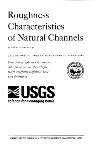
  • 1. Roughness Characteristics of Natural Channels By HARRY II. BARNES, JR. U.S. GEOLOGICAL SURVEY WATER-SUPPLY PAPER 1849 Color photographs and descriptive data for- 50 stream channels for which roughness coe cients have been determined UNITED STATES GOVERNMENT PRINTING OFFICE, WASHINGTON : 1967 Click here to return to USGS publications
  • 2. DEPARTMENT OF THE INTERIOR DONALD PAUL HODEL, Secretary U.S. GEOLOGICAL SURVEY Dallas L. Peck, Director First printing 1967 Second printing 1977 Third printing 1987 For sale by the Books and Open-File Reports Section, U.S. Geological Survey, Federal Center, Box 25425, Denver, CO 80225
  • 3. ������������������� Contents Page Symbols____________________________________________________________________________________ vi Abstract____________________________________________________________________________________ 1 Introduction____________________________________________________________________________ 1 Acknowledgments____________________________________________________________________ 3 Scope of report________________________________________________________________________ 3 Field investigation__________________________________________________________________ 4 Computation of reach properties and roughness coefficients__________________________________________________ 5 Formulas__________________________________________________________________________ 5 Computation procedure________________________________________________ 7 Application of roughness coefficients____________________________________ 7 Presentation of information____________________________________________________ 8 Columbia River at Vernita, Wash . (n = 0 .024)------------ 10 Indian Fork below Atwood Dam, near New Cumberland, Ohio. (n = 0.026)---------------- 14 Champlin Creek near Colorado City, Tex. (n=0 .027)____________________________________________________________________ 18 Clark Fork at St . Regis, Mont. (n = 0.028)------------------ 22 Clark Fork above Missoula, Mont. (n=0 .030) ____________ 26 Columbia River at The Dalles, Oreg. (n = 0 .030) ------ 30 Esopus Creek at Coldbrook, N.Y. (n=0.030) ______________ 34 Salt Creek at Roca, Nebr. (n = 0 .030) -------------------------- 38 Blackfoot River near Ovando, Mont. (n = 0 .031)-------- 42 Coeur d'Alene River near Prichard, Idaho (n = 0 .032) -------------------------------------- 46 Rio Chama near Chamita, N. Mex. (n = 0.032 ; 0 .036) -------------------------------------------------------- 50 Salt River below Stewart Mountain Dam, Ariz. (n=0 .032)____________________________________________________________________ 54 Beaver Kill at Cooks Falls, N.Y. (n=0 .033) ____________ 58 Clearwater River at Kamiah, Idaho (n=0 .033) ______ 62
  • 4. �������������� Presentation of information-Continued Page Etowah River near Dawsonville, Ga . (n=0.041 ; 0.039 ; 0.035)-------------------------------------------- 66 West Fork Bitterroot River near Conner, Mont. (n = 0.036) ____________________________________________________________________ 70 Yakima River at Umtanum, Wash. (n = 0 .036) __________ 74 Middle Fork Vermilion River near Danville, 111. (n = 0.037) ____________________________________________________________________ 78 Wenatchee River at Plain, Wash . (n=0.037)______________ 82 Moyie River at Eastport, Idaho (n=0.038) ---------------- 86 Spokane River at Spokane, Wash. (n = 0.038) ------------ 90 Tobesofkee Creek near Macon, Ga. (n=0.043 ; 0 .041 ; 0 .039) -------------------------------------------- 94 Bull Creek near Ira, Tex. (n=0.041)____________________________ 98 Middle Fork Flathead River near Essex, Mont. (n=0.041)____________________________________________________________________ 102 Middle Oconee River near Athens, Ga . (n=0.042 ; 0 .041 ; 0 .044) ------------------------------- ------------ 106 Beaver Creek near Newcastle, Wyo. (n =0.043) __________ 110 Catherine Creek near Union, Oreg. (n =0.043) ---------- 114 Chiwawa River near Plain, Wash . (n = 0.043)------------ 118 Esopus Creek at Coldbrook, N.Y. (n = 0 .043)-------------- 122 Grande Ronde River at La Grande, Oreg . (n=0 .043)____________________________________________________________________ 126 Murder Creek near Monticello, Ga . (n = 0 .045) -------- 130 Provo River near Hailstone, Utah (n =0 .045 ; 0.073)__ 134 Rolling Fork near Boston, Ky. (n =0.046 ; 0 .097) ------ 138 South Beaverdam Creek near Dewy Rose, Ga. (n=0.052 ; 0.047) -------------------------------------------------------- 142 Deep River at Ramseur, N.C. (n=0.049) ____________________ 146 Clear Creek near Golden, Colo. (n=0.050) ________________ 150 Chattahoochee River near Leaf, Ga. (n=0.051 ; 0 .074) -------------------------------------------------------- 154 South Fork Clearwater River near Grangeville, Idaho (n=0.051) ------------ ------------------------------------------- 158 Cache Creek near Lower Lake, Calif. (n=0.053 ; 0 .079) -------------------------------------------------------- 162 iv
  • 5. ������� Presentation of information- Continued Page East Branch Ausable River at Au Sable Forks, Middle Branch Wemtficld River at Goss Heights, Mama. (n==O.O56) ---------------------------------------------------------- 170 Mission Creek near Cashmere, /m==0.0571_-- 174 HavvRiver near Bpnn1c4 N. C . [o==O.O5q).---------. 178 North Fork Cedar River near Lester, Wash . (n = 0.059) -------------------------------------------------------------------- 182 Hominy Creek at Caod}er, N .C. /n = O .060---------------- 186 Rook Creek Canal near Dnrbn. Moot /m=0,06O-- 190 Merced River at Happy Isles Bridge, near Yosemite, Calif. (n==O.O65)---------------------------------------- 194 Pond Creek near Louisville, Ky. /m==0 .O70---------------- 198 Boundary Creek near PortbD}, Idaho (n=0.073)------ 202 Rock Creek near D»rby' Moot. (m= 0.075) --------------- 206 Selected references------------------------------------------------------------------ 210 Index------------------------------------------.----------------------' 211
  • 6. ������������� Symbols A Area of channel cross section C Flow-resistance factor d Diameter of bed material h Water-surface elevation ha Velocity head hf Energy loss due to boundary friction Oh, Upstream velocity head minus the downstream velocity head A coefficient K Cross section conveyance L Length of reach n Coefficient of roughness Q Discharge R Hydraulic radius S Energy gradient V Average velocity
  • 7. � ROUGHNESS CHARACTERISTICS OF NATURAL CHANNELS By Harry H. Barnes, Jr . Abstract Color photographs and descriptive data are presented for 50 stream channels for which roughness coefficients have been determined . All hydraulic computations involving flow in open channels require an evaluation of the roughness characteristics of the channel. In the absence of a satisfactory quantitative procedure this evaluation remains chiefly an art. The ability to evaluate roughness coefficients must be developed through experience. One means of gaining this experience is by examin­ ing and becoming acquainted with the appearance of some typical channels whose roughness coefficients are known. The photographs and data contained in this report represent a wide range of channel conditions. Familiarity with the appearance, geometry, and roughness characteristics of these channels will improve the engineer's ability to select roughness coefficients for other channels . INTRODUCTION The principal objective of this report is to present descriptive data and photographs for 50 different stream channels for which roughness coefficients have been determined. This information, which has been accumulated by the U.S . Geo­ logical Survey during the past 15 years, was previously availa­ ble only in a photographic slide library in three-dimensional color. Numerous requests for copies of the slides from organi­ zations and private individuals led to the justification for the present report.
  • 8. All hydraulic computations involving flow in open channels require an evaluation of the roughness characteristics of the channel . At the present state of knowledge, the selection of roughness coefficients for natural channels remains chiefly an art. There are no resistance diagrams or quantitative relation­ ships available similar to those used for steady flow in uniform pipes or for the frictional resistance of ships. Consequently the ability to evaluate roughness coefficients for natural channels representing a wide range of conditions must be developed through experience. The experience necessary for the proper selection of rough­ ness coefficients can be obtained in several ways, namely (1) to understand the factors that affect the value of the roughness coefficient, and thus acquire a basic knowledge of the problem, (2) to consult a table of typical roughness coefficients for chan­ nels of various types (Woodward and Posey, 1941), and (3) to examine and become acquainted with the appearance of some typical channels whose roughness coefficients are known. Photographs of channels of known resistance are thus useful in estimating the roughness characteristics of similar channels . The photographs and data presented in this report cover a wide range in conditions. Familiarity with the geometry, appear­ ance, and roughness characteristics of these channels will improve the engineer's ability to select roughness coefficients for other channels . To the untrained beginner, the selection of a roughness coefficient can be no more than a guess; and different indivi­ duals obtain different results. Furthermore, it is sometimes difficult to convince either the layman or the scientist that consistently reliable roughness coefficients can be selected by trained engineers on the basis of sound judgment and experi­ ence. Fortunately, even though the, selection of the coef­ ficients is classified as an art, the accuracy of many selections can be evaluated in exact engineering or statistical terms. The ability to evaluate the roughness characteristics of channels is important in the hydraulic work of the U.S . Geo­ logical Survey. This ability, for example, is involved in the
  • 9. � methods (Benson and Dalrymple, 1966 ; Dalrymple and Ben­ son, 1966 ; Bodhaine, 1966 ; Matthai, 1966 ; Hulsing, 1966) which are used in defining the peak discharge of most major floods. For this reason the Survey maintains a program which both trains young engineers in the evaluation of channel roughness and tests the accuracy of roughness coefficients by veteran engineers. The results of these tests as reported by Bailey and Ray (1966) indicate that trained engineers can select roughness coefficients with an accuracy of plus or minus 15 percent under most conditions. These facts prove that present methods are sound but that there is much room for improvement. A quantitative procedure for determining the roughness characteristics of channels has been the goal of research in the Survey and in other organizations for many years, but as yet little practical success has been achieved. ACKNOWLEDGMENTS Data contained in this report represent contributions by many engineers of the U .S. Geological Survey. Much credit is due Hollister Johnson and Tate Dalrymple who conceived and promoted the Survey's program to verify roughness coefficients in natural channels. The author gratefully acknowledges the advice and assist- ance of R . W. Carter, W. R. Stokes, E. D. Cobb, and R. E . Smith. SCOPE OF REPORT Information on the geometry and roughness characteristics of 50 different stream channels is presented in the report. All of the stream channels are considered to be stable . Sand- channel streams were not included in the report because roughness coefficients for streams of this type have been defined in terms of size of bed material and other variables (Simons and Richardson, 1962) . The 50 sites include a wide range of hydraulic conditions from the boulder-strewn mountain stream of the western conterminous United States to the heavily vegetated flat- sloped stream of the southern conterminous United States . 3
  • 10. � The techniques used in field investigations at each site are first discussed in the report. The procedures used in comput­ ing the value of the roughness coefficient are then described. The remainder of the report consists of the presentation of a set of data and photographs for each of the 50 sites. FIELD INVESTIGATION Sites were selected for study after a major flood had occurred in a given region. Each site met the following criteria: 1 . The peak discharge of the flood was measured by the current-meter method, or determined from a well-defined stage-discharge relation ; 2 . Good high-water marks were available to define the water- surface profile at the time of the peak ; 3 . A fairly uniform reach of channel was available near the gage; 4. The flood discharge was within the channel banks-that is, extensive flow in flood plains did not exist. A transit-stadia survey of each reach was completed shortly after the flood. The necessary information was obtained in this survey to plot accurately to a common datum (1) the water-surface profile as represented by high-water marks, (2) a plan view of the reach, (3) cross sections at intervals along the reach . Surveying techniques used in this investigation are described in detail by Benson and Dalrymple (1966) . Photographs of the. reach were taken during the time of the survey. The photographs shown in this report thus represent conditions in the reach immediately after the flood. A size description of the bed material at most of the sites was determined by sampling methods (Wolman, 1954) . These samples were in general taken several years after the flood for which the roughness coefficient was determined. The samples may or may not be representative of the bed material at the time of the peak . Frequency distributions of bed- material size were determined by sieve analysis where the medium size of the material was less than 50 mm and, where the material was too large to sieve, by measuring the inter­ mediate axis of particles selected at random from the bed surface. 4
  • 11. � COMPUTATION OF REACH PROPERTIES AND ROUGHNESS COEFFICIENTS Formulas Most open-channel flow formulas can be expressed in the following general terms, Q=C A Rz S' (1) where Q is the discharge, in cubic feet per second ; C is a factor of flow resistance ; A is the cross-sectional area of the channel, in square feet ; R is the hydraulic radius, in feet ; and S is the energy gradient. The Manning equation, one of the well-known variations of equation 1, was used as the basis for computing the reach properties and roughness co­ efficients given in this report. The Manning equation is __ 1 .486 AR2/3 5112 Q' n where n is a roughness coefficient and other variables in the equation are as defined above. The Manning equation was developed for conditions of uniform flow in which the water-surface profile and energy gradient are parallel to the streambed, and the area, hydraulic radius, and depth remain constant throughout the reach. For lack of a better solution, it is assumed that the equation is also valid for nonuniform reaches, invariably found in natural channels, if the energy gradient is modified to reflect only the losses due to boundary friction. The energy equation for a reach of nonuniform channel between sections 1 and 2 in figure 1 is (see p. J) (h+h,), = (h+hv)2+(hf)1.2+k(Ohv), .2 where h =elevation of the water surface at the respective sections above a common datum; hr, = velocity head at the respective section = «V2/2g; hf= energy loss due to boundary friction in thereach; 5
  • 12. ������ Ahv =upstream velocity head minus the downstream velocity head ; k(Ahv) = energy loss due to acceleration of velocity or deceleration of velocity in a contracting or expanding reach; and k=a coefficient taken to be zero for contracting reaches and 0.5 for expanding reaches. In computing the values of n listed in this report the value of «, the velocity head coefficient, was always considered to be 1 .00. The friction slope S to be used in the Manning equation is thus defined as S=hy Ah+Ah,-k(Ah,) (4) L L where Ah is the difference in water-surface elevation at the two sections and L is the length of the reach. In using the Manning equation the quantity (1 .486/n)AR2 i 3 , called conveyance and designated K, is computed for each cross section. The mean conveyance in the reach between any two sections is computed as the geometric mean of the conveyance of the two sections . The discharge equation in terms of conveyance is Q= 11K2 S where S is the friction slope as previously defined. In this investigation the average value of the Manning n was computed for each reach from the known discharge, the water­ surface profile, and the hydraulic properties of the reach as defined by 2-17 cross sections. The following equation, which is based on the same concepts and definitions as equa­ tions 2-5, was used in these computations. The equation is applicable to a multisection reach of M cross sections which are designated 1, 2, 3, . . . M-1, M. 1.486 (h+ha)1-(h+hv)M-[(k Ohv)1.2+(k Ohv)2.3+. . .-1­ n= Q ~L .2 + L2.3 . . . +L(m-1).M Z1 Z2 Z2Z3 z(M-1)ZM (k Ahv)(M-1).M] (6) where Z = AR21' and other quantities are as previously defined. 6
  • 13. ������ Computation Procedure A planimetric map of each reach was developed by plotting from the notes of the field survey. The location of all high water marks and cross sections was shown on the map. The distances between cross sections were determined from the map. The profile of the water surface through the reach was developed separately along each bank by plotting the elevation and stationing of high-water marks. The water-surface ele­ vation at each cross section was determined as the average of the water-surface elevation on each bank as taken from the water-surface profiles. Cross sections were plotted from the field notes, and data on stationing, distance, ground elevations, depths, and top widths were tabulated. The area and wetted perimeter for each panel between given ground elevations were computed. The area, wetted perimeter, and hydraulic radius for each cross section were determined, and values of AR"' were computed. The average value of n for each reach was then determined by substituting the proper quantities in equation 6. The computation procedure is virtually the same as for com­ putation of discharge by the slope-area method . This pro­ cedure is described in detail by Dalrymple and Benson (1966) . APPLICATION OF ROUGHNESS COEFFICIENTS The values of n presented in the report are intended for use in the Manning equation V _ 1 .486 R2/3 5112 (English units) n R2/3 S112 or V (metric units) n The value of n may be converted to values of the Chezy Cby the relation = 1 .486 R116 C (English units) n and the value of C may then be used in the Chezy equation V=CRS
  • 14. �� All these equations are limited to turbulent flow in fully rough channels. Flow in natural channels normally meets this criterion. PRESENTATION OF INFORMATION A four-page set consisting of channel data, plan sketches (not to scale) and cross sections, and photographs, is presented for each reach in the following section of the report. Each set of data is identified by the permanent gaging-station number and name used by the U.S. Geological Survey in publication of streamflow-records . The data tabulation shows the location of the gage and a reference cross section, the drainage area of the stream, the date of the flood, the peak gage height at the gage and at sec­ tion 1 during the flood, the peak discharge measured by cur- rent-meter method, the computed roughness coefficient for the reach, a general description of the channel, the median bed- material size, d o, and the reference size for which 84 percent of the bed material is finer, d84. The area, top width, mean depth (area/top width), hydraulic radius, and mean velocity corresponding to the water-surface elevation at the time of the peak are listed for each cross section. The distance or length between cross sections and the fall in water surface between cross sections are also shown. Information for two or more peak discharges is available at some sites. These data are listed according to the magnitude of discharge. Data cor­ responding to the largest discharge appear first. At several sites a small percentage of the flow occurred in the shallow flood plain adjacent to the main channel. For each of these sites the data and computations reflect the flow of the main channel . Data for the site, Rolling Fork at Boston, Ky., are unique in that roughness coefficients were computed for both the over­ flow plain and the main channel. Two color photographs taken immediately after the flood are shown for each reach . The position of the camera and the
  • 15. ��� number of the picture are shown on the plan sketch by a pointer, which shows the direction in which the camera was pointed. The water level at the time of the peak is indicated in some of the photographs by a horizontal rod or tape. The initial station for cross sections is at the left bank. Plots are arranged so that the left bank appears on the reader's left. The water levels shown on the cross sections correspond to the water-surface profile at the time of the peak as defined by high-water marks. Sites are arranged according to the value of the computed roughness coefficient, in ascending order. i "*-Section 1 -1. Section 2,,rj. v t PLAN VIEW hvl I 1 ~ ---- - E rgy gradient Ihf+k(Ah) Water surface [hv2 Datum L PROFILE VIEW Figure 1. -Definition sketch of a slope-area reach.
  • 16. ���� n = 0.024 12-4645. Columbia River at Vernita,Wash. Gage location.-In sec. 11, T. 13 N., R. 24 E., at the Richmond ferry site, 0.5 mile north of Vernita station. Gage presently operated 50 miles upstream for station called Columbia River at Trinidad, Wash. Section 1 is 5,000 ft upstream from cableway at Vernita gage. Drainage area.-89,700 sq mi, approximately. Date offlood.-May 22, 1949 . Gage height.-48 .33 ft at Trinidad gage ; 29 .5 ft (different datum) at section 1 . Peak discharge.-406,000 cfs. Computed roughness coefficient. -Manning n=0.024. Description of channel.-Bed consists of slime-covered cobbles and gravel . The straight and steep left bank is composed of cemented cobbles and gravel. The gently sloping right bank consists of cobbles set in gra;-e1 and is free of vegetation. Reach properties Section Area (sq ft) Top width (ft) Mean depth (ft) Hydraulic radius (ft) Mean velocity (ft per sec) Length (ft) between sections Fall (ft) between sections 1 . . . . . . . . . . . 2 . . . . . . . . . . . 3 . . . . . . . . . . . 47,100 49,000 49,600 1,800 1,650 1,760 26.2 29 .7 28.2 26 .16 29,56 28.10 8.65 8.28 8.17 . . . . . . . . . . . . 2,500 2,500 . . . . 0.48 .49 Notes.-
  • 17. n = 0.024 CROSS SECTIONS Plan sketch and cross sections, Columbia River at Vernita, Wash.
  • 18. n = 0.024 No. 67 upstream from top of bank at section 3, Columbia River at Vernita, Wash. 1 2
  • 19. n = 0.024 No . 66 upstream along right bank from section 3, Columbia River at Vernita, Wash . 1 3
  • 20. � n = 0.026 3-1215. Indian Fork belowAtwood Dam, near NewCumberland, Ohio Gage location.-Lat 40°31'30, long 81°17'20, in SEY4 sec. 28, T. 15 N., R. 7 W., on left bank 500 ft downstream from Atwood Dam, 0 .5 mile upstream from mouth, and 1 .5 miles southeast of New Cumberland, Tuscarawas County. Sec­ tion 1 is about 300 ft downstream from gage. Drainage area.-70 .3 sq mi. Date offood.-May 11, 1948. Gage height.-10.27 ft at gage ; 9.99 ft at section 1 . Peak discharge.-768 cfs. Computed roughness coefficient. -Manning n=0.026 . Description of channel.-Bed and banks are composed of clay. Banks are clear except for short grass and exposed tree roots in some places. Reach Properties Top Mean Hydraulic Mean Length (ft) Fall (ft) Section I Area width depth radius velocity between between (sq ft) (ft) (ft) (ft) (ft per sec) sections . sections 1 . . . . . . . . . . . 280 52 5.4 4.87 2.74 . . . . . . . . . . . . . , . . 2 . . . . . . . . . . . 273 51 5.4 4.82 2.82 257 0.08 3 . . . . . . . . . . . 279 52 5.4 4.97 2.76 202 .05 Notes.-
  • 21. n = 0.026 CROSS SECTIONS 12 10 8 6 4 2 10 8 6 4 2 10 8 6 4 2 0 10 20 30 40 50 60 WIDTH, IN FEET Plan sketch and cross sections, Indian Fork below Atwood Dam, near New Cumberland, Ohio. 1 5
  • 22. n = 0.026 No. 327 upstream from right bank below section 3, Indian Fork belowAtwood Dam, near New Cumberland, Ohio. 16
  • 23. n = 0.026 No. 329 upstream from right bank at section 2, Indian Fork belowAtwood Dam, near New Cumberland, Ohio. 17
  • 24. � n = 0.027 8-1235 . Champlin Creek near Colorado City, Tex. Gage location.-Lat 32°19', long 100°49', on right bank 600 ft downstream from South Fork, 5 miles southeast of Colorado City, Mitchell County, and 5 .5 miles upstream from mouth . Section 2 is 350 ft downstream from gage. Drainage area.-158 sq mi . Date offood.-May 17, 1949 . Gage height.-5 .05 ft at gage; 4 .24 ft at section 2 . Peak discharge.-2,390 cfs. Computed roughness coefficient. -Manning n=0.027 . Description of channel.-Bed consists of gravel deposits over smooth to rough rock. Banks are covered with grass and have a few outcrops . Reach properties Section Area (sq ft) Top width (ft) Mean depth (ft) Hydraulic radius (ft) Mean velocity (ft per s°_ 7) Length (ft) between sections Fall (ft) between sections 2 . . . . . . . . . . . 412 85 4.8 4.71 5.80 . . . . . . . . . . . . . . . . 3 . . . . . . . . . . . 344 79 4.4 4.20 6.96 176 0.43 4 . . . . . . . . . . . 307 70 4.4 4.24 7.78 148 .71 Notes.-
  • 25. n = 0.027 CROSS SECTIONS a0 W a H W W Z Z _Z 0 J W Plan sketch and cross sections, Champlin Creek near Colorado City, Tex. 1 9
  • 26. n = 0.027 No. 511 downstream along right bank from above section 2, Champlin Creek near Colorado City, Tex. 20
  • 27. n = 0.027 No. 512 upstream along left bank from below section 4, Champlin Creek near Colorado City, Tex. 2 1
  • 28. � n = 0.028 12-3 545 . Clark Fork at St. Regis, Mont. Gage location.-Lat 47° 18'05, long 115° 05'15, in center of SW Y4 sec. 19, T. 18 N., R. 27 W., on left bank at St. Regis, 0.5 mile downstream from St. Regis River. Section 1 is 660 ft upstream from gage. Drainage area.-10,709 sq mi . Date offlood.-May 24, 1948 . Gage height.-19 .96 ft at gage ; 20.42 ft at section 1 . Peak discharge.-68,900 cfs. Computed roughness coefficient.-Manning n = 0.028 . Description of channel.-Bed consists of well-rounded boulders; d5o =135 mm, d84 = 205 mm. Banks are composed of gravel and boulders, and have tree and brush cover. Reach properties Top Mean Hydraulic Mean Length (ft) Fall (ft) Section Area width depth radius velocity between between (sq ft) (ft) (ft) (ft) (ft per sec) sections sections 1 . . . . . . . . . . . 6,860 404 16.98 16.70 10.04 . . . . . . . . . . . . . . . . 2 . . . . . . . . . . . 6,976 429 16.26 16.04 9.88 755 0.555 3 . . . . . . . . . . . 7,194 454 15.85 15.64 9.58 438 .32 Notes.-
  • 29. n = 0.028 CROSS SECTIONS a 0 W a 20 H W W W 10 Z Z F­ a W J W Plan sketch and cross sections, Clark Fork at St. Regis, Mont. 23
  • 30. n = 0.028 No. 22 downstream along right bank from section 2, Clark Fork at St. Regis, Mont. 24
  • 31. n = 0.028 No. 23 upstream along left bank from section 2, Clark Fork at St. Regis, Mont. 25
  • 32. n = 0.030 12-3405 . Clark Fork above Missoula, Mont. Gage location.-Lat 46°52'40, long 113°55'40, in NWY4NWj sec . 19, T . 13 N, R. 18 W., on right bank 3 miles down- stream from Blackfoot River and 3 miles east of Missoula . Section 1 is 405 ft upstream from gage. Drainage area.-5,999 sq mi . Date offlood.-May 23, 1948 . Gage height.-13 .07 ft at gage ; 14 .54 ft at section 1 . Peak discharge.-31,500 cfs . Computed roughness coefficient. -Manning n = 0.030. Description of channel.-Bed is composed of sand, gravel, and boulders ; d5o =175 mm, d84 = 325 mm. Thick undergrowth is along right bank and along the left bank in the lower part of the reach. Reach Properties Section Area (sq ft) Top width (ft) Mean depth (ft) Hydraulic radius (ft) Mean velocity (ft per sec) Length (ft) between sections Fall (ft) between sections 1 . . . . 2 . . . . 3 . . . . 4 . . . . . . . . . . . . . . . . . . . . . . . . . . . . . . . . 3,866 3,461 3,634 3,798 285 267 294 312 13.56 12.96 12.36 12.17 13.24 12.64 12.10 11 .95 8.15 9.10 8.67 8.29 . . . . . . . . 305 243 297 . . . . . . . . 0.63 .25 .18 Notes. -
  • 33. �� n = 0.030 a 0 W a 0 W W z z 0 a W J W PLAN SKETCH 2 /1 3 4 Gage I 2 CROSS SECTIONS WIDTH, IN FEET Plan sketch and cross sections, Clark Fork above Missoula, Mont. 27
  • 34. n = 0.030 No. 18 downstream along left bank from above section 3, Clark Fork above Missoula, Mont. 28
  • 35. n = 0.030 No. 19 downstream through reach from bridge 400 ft above section 1, Clark Fork above Missoula, Mont. 29
  • 36. n = 0.030 14-1057 . Columbia River at The Dalles, Oreg. Gage location .-Lat 45°36'10, long 121°10'40, in NWY4 sec. 3, T. 1 N., R. 13 E., at upstream end of Port of The Dalles dock at The Dalles, 3 .2 miles downstream from The Dalles Dam and at mile 189 .3 . Section 4 is at cableway 9 miles upstream from gage . Drainage area .-237,000 sq mi, approximately. Date offlood.-May 31, 1948 . Gage height .-154 .56 ft at gage ; 171 .44 ft at section 1 . Peak discharge .-1,000,000 cfs . Computed roughness coefficient.-Manning n = 0 .030. Description of channel.-Left bank consists of sand, gravel, and boulders, and has light cover of brush in some places . Right bank is formed by severely scalloped basalt cliffs . The bed material is fairly well graded from 18-inch boulders along the left bank down to sand at the base of the right bank. Reach Properties Section Area (sq ft) Top width (ft) Mean depth (ft) Hydraulic radius (ft) Mean velocity (ft per sec) Length (ft) between sections Fall (ft) between sections 1 . . . . . . . . . . . 94,650 1,980 47 .80 47 .28 10.57 . . . . . . . . . . . . . . 2 . . . . . . . . . . . 90,810 1,640 55.37 54.10 11 .01 2,003 . 0.50 3 . . . . . . . . . . . 89,040 1,485 59.96 57.80 11 .23 778 .20 4 . . . . . . . . . . . 91,890 1,600 57.43 55 .81 10.88 1,394 .41 Notes.-
  • 37. n = 0.030 CROSS SECTIONS 250 200 Water surface 5/31/48 I I i I 150 1 100 200 150 100 * Properties of overflow sections not included in table 200 I 150 3 100 50 200 150 I4 100 50 0 500 1000 1500 2000 2500 3000 3500 WIDTH, IN FEET Plan sketch and cross sections, Columbia River at The Dalles, Oreg. 31
  • 38. No. 47 downstream along right bank from above section 1, Columbia River at The Dalles, Oreg. 32
  • 39. n = 0.030 No. 38 upstream along left bank from section 4, Columbia River at The Dalles, Oreg. 33
  • 40. � n = 0.030 1--362 5 . Esopus Creekat Coldbrook, N.Y. Gage location .-Lat 42°00'45, long 76°16'10, on left bank at downstream side of highway bridge at Coldbrook, Ulster County, 1 .5 miles upstream from Ashokan Reservoir and 2.5 miles south of Mount Tremper. Section 1 is about 400 ft upstream from Highway 28-A, which is about 6 miles southeast of gage . Drainage area.-192 sq mi. Date offood.-Mar . 22, 1948. Gage height.-12.39 ft at gage; 15 .60 ft (different datum) at section 1 . Peak discharge.-13,900 cfs. Computed roughness coefficient.-Manning n=0 .030. Description of channel.-The bed is coarse gravel and both banks are lined with trees and brush. Reach Properties Section Area (sq ft) Top width (ft) Mean depth (ft) Hydraulic radius (ft) Mean velocity (ft per sec) Length (ft) between sections Fall (ft) between sections 1 . . . . . . . . 2 . . . . . . . . . . . . . . 1,600 1,589 301 284 5.3 5.6 5.28 5.54 8.70 8.77 . . . . . . . . . . . . . . . . 471 1 .60 Notes . -
  • 41. PLAN SKETCH 2 CROSS SECTIONS a 0 a m a W W W Z Z H a W J W Plan sketch and cross sections, Esopus Creek at Coldbrook, N.Y. 35
  • 42. n = 0.030 No. 354 upstream along left bank from section 2, Esopus Creek at Coldbrook, N.Y. 36
  • 43. n = 0.030 No. 357 upstream from right end of bridge below reach, Esopus Creek at Coldbrook, N.Y. (at Highway 28-A) . 37
  • 44. �� n = 0.030 6-8030. Salt Creek at Roca, Nebr. Gage location.-Lat 40°39'33, long 96°39'39, in SWY4 sec. 17, T . 8 N., R . 7 E., on left bank 15 ft downstream from highway bridge at west edge of Roca . Section 1 is 75 ft downstream from gage . Drainage area.-174 sq mi. Date offood.-May 2, 1954. Gage height.-16 .02 ft at gage ; 15 .94 ft at section 1 . Peak discharge.-1,860 cfs. Computed roughness coefficient. -Manning n = 0.030. Description of channel.-Bed consists of sand and clay. Banks are generally smooth and are free of vegetal growth during floods. Reach properties Section Area (sq ft) Top width (ft) Mean depth (ft) Hydraulic radius (ft) Mean velocity (ft per sec) Length (ft) between sections Fall (ft) between sections 1 . . . . . . . . . . . 528 72 7.4 6.7 3.46 . . . . . . . . . . . . . . . . 2 . . . . . . . . . . . 502 80 6.3 5.9 3.71 113 0.09 3 . . . . . . . . . . . 497 69 7.2 6.6 3.74 110 .06 4 . . . . . . . . . . . 497 78 6.4 5.9 3.74 134 .05 Notes.-
  • 45. n = 0.030 825 4 CROSS SECTIONS a 0 W a W W W Z Z H a W J W Plan sketch and cross sections, Salt Creek at Roca, Nebr. 39
  • 46. n = 0.030 No. 824 downstream from above section 1, Salt Creek at Roca, Nebr. 40
  • 47. n = 0.030 No. 825 downstream from below section 2, Salt Creek at Roca, Nebr . 41
  • 48. � n = 0.031 12-3385. Blackfoot River near Ovando, Mont. Gage location.-Lat 47°01'10, long 113 ° 13'40, in SEY4NWY4 sec. 34, T. 15 N., R. 13 W., . on left bank 0.25 mile upstream from Monture Creek and 5 miles west of Ovando. Section 1 is about 0.25 mile upstream from gage . Drainage area.-1,274 sq mi. Date offood.-May 22, 1948 . Gage height .-6 .84 ft at gage ; 16.34 ft at section 1 . Peak discharge.-8,200 cfs . Computed roughness coefficient .-Manning n = 0 .031 . Description of channel.-Bed is gravel and boulders ; d5o = 155 mm, d84 = 280 mm. Banks consist of same material and are relatively free of vegetation . Reach properties Top Mean Hydraulic Mean Length (ft) Fall (ft) Section Area width depth radius velocity between between (sq ft) (ft) (ft) aft) (ft per sec) sections sections 1 . . . . . . . . . . . 1,230 199 6.18 6.12 6.67 . . . . . . . . . . . . . . 2 . . . . . . . . . . . 1,140 189 6.03 5,97 7.19 292 0.68 Notes.-
  • 49. n = 0.031 PLAN SKETCH 2 CROSS SECTIONS 18 16 14 12 Q 10 W Q 8 W W W Z Z 16 Q wJ w 14 12 10 40 80 120 160 200 WIDTH, IN FEET Plan sketch and cross sections, Blackfoot River near Ovando, Mont. 43
  • 50. n = 0.031 No . 1 downstream from left bank above section 1, Blackfoot River near Ovanda, Mont. 44
  • 51. n = 0.031 No. 3 upstream towards right bank from below section 2, Blackfoot River near Ovanda, Mont. 45
  • 52. � n = 0.032 12-4120. Coeur d'Alene River near Prichard, Idaho Gage location .-Lat 47°38'05, long 115°58'55, in lot 7, sec. 32, T. 50 N., R. 4 E., on right bank 0.2 mile downstream from Beaver Creek and 1 .75 miles southwest of Prichard. Sec­ tion 1 is 570 ft upstream from gage . Drainage area .-583 sq mi. Date offood.-May 21, 1948 . Gage height.-9 .24 ft at gage; 10.98 ft at section 1 . Peak discharge.-11,300 cfs. Computed roughness coefficient.-Manning n = 0 .032. Description of channel.-Bed is composed of rock along left edge, gravel and small boulders elsewhere ; dso =103 mm, d8, = 650 mm. Left bank is irregular bedrock, steep and clean. Right bank consists of sand and gravel covered with heavy growth of brush and trees. Reach properties Section Area (sq ft) Top width (ft) Mean depth (ft) Hydraulic radius (ft) Mean velocity (ft per sec) Length (ft) between sections Fall (ft) between sections 1 . . . . . . . . . . . 2 . . . . . . . . . . . 3 . . . . . . . . . . . 4 . . . . . . . . . . . 1,260 1,200 1,306 1,312 162 141 159 185 7 .8 8.5 8.2 7.1 7 .65 8.00 7.96 6.87 8.97 9.42 8.65 8.61 . . . . . . . . 230 400 302 . . . . . . . . 0.50 .88 .92 Notes.-
  • 53. 0 n = 0.032 PLAN SKETCH 3 CROSS SECTIONS W H W WU­ Z WJ W Plan sketch and cross sections, Coeur d'Alene River near Prichard, Idaho. 47
  • 54. n = 0.032 No. 34 downstream through reach from right bank, Coeur d'Alene River near Prichard, Idaho. 48
  • 55. n = 0.032 No. 36 downstream along right bank at section 1, Coeur d'Alene River near Pritchard, Idaho. 49
  • 56. � n = 0.032; 0.036 8-2900. Rio Chama near Chamita, N. Mex. Gage location .-Lat 36°04'25, long 106°06'39, in NEY4NEj sec . 8, T. 21 N ., R . 8 E., on left bank 200 ft downstream from bridge on U.S . Highway 285, 0 .5 mile west of Chamita, 2.5 miles northwest of San Juan Pueblo, and 3 miles upstream from mouth. Section 1 is about 200 ft upstream from gage. Drainage area.-3,140 sq mi . Date offlood.-Mar. 24, 1950 ; Apr. 3, 1950 . Gage height.-3.41 ft, 2 .95 ft at gage ; 3 .65 ft, 3 .18 ft at section 1 . Peak discharge.-1,060 cfs ; 684 cfs. Computed roughness coefficient. -Manning n=0.032 ; 0.036 . Description of channel.-The bed consists of sand and gravel . The left bank is rock and the right bank is mostly gravel . Reach Properties Section Area (sq ft) Top width (ft) Mean depth (ft) Hydraulic radius (ft) Mcan velocity (ft per sec) Length (ft) between sections Fall (ft) between sections Mar . 24, 1950 1 . . . . . . . . . . . 2 . . . . . . . . . . . 312 297 95 84 3 .3 3 .5 3 .12 3 .45 3 .40 3 .57 202 . . . . . 0 .24 Apr. 3, 1950 1 . . . . . . . . . . . 235 92 2.6 2 .52 2.91 2 . . . . . . . . . . . 249 81 3.1 2 .95 2.75 . . . . 202 . . . .'0.23 Notes .­
  • 57. n = 0.032; 0.036 PLAN SKETCH CROSS SECTIONS 6 2 Q H w ww 20 40 60 80 100 120 Z Z 4 O I i Q 2 J w w 0 20 40 60 80 100 120 WIDTH, IN FEET Plan sketch and cross sections, Rio Chaina near Chamita, New Mex. 5 1
  • 58. n = 0.032; 0.038 No. 547 upstream along right bank from below section 2, Rio Chama near Chamita, N. Mex. 52
  • 59. = 0 0550 downstream from bank at section Rio ChamaN MexrightChamita, 1, n .032; .036 No. near . . 53
  • 60. n = 0.032 9-5020. Salt River below Stewart Mountain Dam, Ariz . Gage location .-Lat 33°33'00, long 111'34'31, in NY2NWY4 sec. 6, T. 2 N., R. 8 E. (unsurveyed), on left bank 3.5 miles downstream from Stewart Mountain Dam and 6 miles upstream from Verde River. Section 1 is about 2.25 miles downstream from gage . Drainage area.-6,230 sq mi, of which 21 sq mi is below Stewart Mountain Dam. Date offood.-Mar. 24, 1950 . Gage height .-4.26 ft at gage ; 99 .26 ft (different datum) at section 1 . Peak discharge.-1,280 cfs. Computed roughness coefficient.-Manning n = 0.032 . Description of channel .-Bed and banks consist of smooth cobbles 4 to 10 inches in diameter, average diameter about 6 inches. A few boulders are as much as 18 inches in diameter . Reach properties Section Area (sq ft) Top width (ft) Mean depth (ft) Hydraulic radius (ft) Mean velocity (ft per sec) Length (ft) between sections Fall (ft) between sections 1 . . . . . . . . . . . 484 189 2.6 2.55 2.65 . . . . . . . . . . . . . . . . 2 . . . . . . . . . . . 408 192 2.1 2.12 3.14 258 0.37 3 . . . . . . . . . . . 384 154 2.6 2.49 3.34 317 .50 4 . . . . . . . . . . . 449 194 2.3 2.30 2.86 294 .31 5 . . . . . . . . . . . 420 204 2.1 2.06 3.05 370 .63 6 . . . . . . . . . . . 381 207 1 .8 1 .84 3.36 333 .72 7 . . . . . . . . . . . 308 191 1 .6 1 .61 4.16 314 1 .06 Notes.-
  • 61. n = 0 .032 Q oc Q GC H mOC Q w ww Z Z O Q wJ W WIDTH,IN FEET Plan sketch and cross sections, Salt River below Stewart Mountain Dam, Ariz . 55
  • 62. n = 0.032 low No. 817 upstream along left bank from below section 6 Salt River below Stewart Mountain Dam, Ariz. 56
  • 63. n = 0.032 No. 818 downstream along left bank from section 2, Salt River below Stewart Mountain Dam, Ariz. 57
  • 64. �� n = 0.033 1-4205 . Beaver Kill at Cooks Falls, N.Y. Gage location.-Lat 41'56'50, long 74°58'45, on left bank 125 ft downstream from highway bridge in Cooks Falls, Dela­ ware County, and 5.5 miles downstream from Willowemoc Creek. Section 5 is about 2,700 ft downstream from gage. Drainage area .-241 sq mi . Date offood.-Mar . 22, 1948. Gage height.-11 .69 ft at gage ; 42.65 ft (different datum) at section 5 . Peak; discharge.-15,500 cfs. Computed roughness coefficient . -Manning n=0 .033 . Description of channel.-Bed consists of coarse gravel and cobbles with scattered boulders. Light brush is on both banks and some trees are near water's edge on right bank . Reach properties Section Area (sq ft) Top width (ft) Mean depth (ft) Hydraulic radius (ft) Mean velocity (ft per sec) Length (ft) between sections Fall (ft) between sections 5 . . . . . . . . . . . 6 . . . . . . . . . . . 7 . . . . . . . . . . . 1,700 1,660 1,590 244 221 206 7.0 7.5 7.7 6 .85 7.36 7.59 9 .11 9 .33 9 .72 . . . . . . . 279 283 . . . . . . . 0.65 1 .25 Notes.-
  • 65. n = 0.033 PLAN SKETCH 5 6 I I 6 7 CROSS SECTIONS 48 44 40 36 Q 32 O Q 44 m Q 40 w w 36 w Z 32 Z O Q 44 wJ w 40 36 32 30 0 50 100 150 200 250 300 WIDTH, IN FEET Plan sketch and cross sections, Beaver Kill at Cooks Falls, N.Y. 59
  • 66. n = 0.033 No. 366 upstream toward right bank from section 7, Beaver Kill at Cooks Falls, N.Y. 60
  • 67. n = 0.033 No . 367 upstream along left bank from section 7, Beaver Kill at Cooks Falls, N.Y. 61
  • 68. � n = 0.033 13-3390. Clearwater River at Kamiah, Idaho Gage location .-Lat 46°14', long 116°01', in sec. 1, T. 33 N., R . 3 E., on left bank 0.25 mile downstream from highway bridge at Kamiah, 0.75 mile downstream from Lawyer Creek, and 6 miles downstream from South Fork. Section 1 is about 5 .8 miles downstream from gage. Drainage area.-4,850 sq mi, approximately . Date offood.-May 29, 1948 . Gage height.-19 .22 ft at gage; 46 .17 ft at section 1 . Peak discharge.-99,000 cfs. Computed roughness coefficient.-Manning n = 0.033 . Description of channel.-Bed is composed of gravel and boulders with some exposed bedrock. Channel is bordered by rail­ road on the right and highway on the left. Banks are gravel and rock and have light vegetation cover. Reach Properties Section Area (sq ft) Top width (ft) Mean depth (ft) Hydraulic radius (ft) Mean velocity (ft per sec) Length (ft) between sections Fall (ft) between sections 1 . . . . . . . . . . . 2 . . . . . . . . . . . 3 . . . . . . . . . . . 11,100 11,603 10,937 562 593 538 19.25 19 .58 20.32 19.45 19 .34 20.04 8.92 8.53 9.05 . . . . . . . .732 560 . . . . . . . . 0.35 .67 Notes.-
  • 69. 0 n = 0.033 CROSS SECTIONS a r a m a W w z z O a wJ LL/ Plan sketch and cross sections, Clearwater River at Kamiah, Idaho . 63
  • 70. = 0 29 downstream left bank from above sectionRiver at Idahoalong Kamiah, 1, n .033 No. Clearwater . 64
  • 71. n = 0.033 No. 32 upstream from left bank at section 3. Clearwater River at Kamiah, Idaho. 65
  • 72. �������� n = 0.041; 0.039; 0.035 2-3890. Etowah River near Dawsonville, Ga. Gage location .-Lat 34°23', long 84°04', on left bank 0.5 mile upstream from Palmer Creek, 1 mile downstream from Russell Creek, 4 miles southeast of Dawsonville, Dawson County, and 7 .5 miles upstream from Shoal Creek . Section 7 is 477 ft downstream from gage. Drainage area .-103 sq mi . Date of food.-Jan . 22, Feb . 13, Feb. 14, 1959 . Gage height.-9.45 ft, 7 .95 ft, 2 .85 ft at gage ; 9 .02 ft, 7 .55 ft, 2 .18 ft at section 7 . Peak discharge.-2,260 cfs ; 1,850 cfs ; 515 cfs. Computed roughness coefficient.-Manning n = 0 .041 ; 0 .039 ; 0 .035 . Description of channel.-Bed is sand and gravel with several fallen trees in the reach. Banks are lined with overhanging trees and underbrush. Reach Properties Section Area (sq ft) Top width (ft) Mean depth (ft) Hydraulic I Mean ~ Length (ft) radius velocity between (ft) (ft per sec) sections Fall (ft) between sections Jan.22, 1959 7 . . . . . . . . . . . 618 60 10.3 8 .15 3.66 . . . . . . . . . . . . 8 . . . . . . . . . . . 621 66 9 .4 7 .77 3.64 .316 . 220 9 . . . . . . . . . . . 619 63 9 .8 8 .18 3.65 286 18 10 . . . . . . . . . . 610 63 9.7 7 .77 3.70 293 14 11 . . . . . . . . . . 622 66 9.4 7 .89 3.63 203 17 Feb. 13, 1959 7 . . . . . . . . . . . 528 57 9 .3 7.37 3.50 . . . . . . . . . . . . . . 8 . . . . . . . . . . . 531 64 8 .3 6.95 3.48 316 . . 0.19 9 . . . . . . . . . . . 532 59 9 .0 7 .56 3.48 286 .20 10 . . . . . . . . . . 525 61 8 .6 7.00 3.52 293 .14 11 . . . . . . . . . . 530 62 8 .6 7.10 3.49 203 .14 Feb. 14, 1959 7 . . . . . . . . . . . 240 51 4.7 4.04 2.15 . . . . . . . . . . . . . . . . 8 . . . . . . . . . . . 209 59 3.5 3 .27 2.46 316 0.16 9 . . . . . . . . . . . 10 . . . . . . . . . . 235 203 53 59 4.4 3.4 I 4.04 3 .19 2.19 2.54 286 293 .17 .19 11 . . . . . . . . . . 219 55 4.0 3 .59 2.35 203 .15 Notes.- 66
  • 73. Gage n = 0.041; 0.039; 0.035 f- Q 0 W Q H W W U­ Z Z H Q 1W J W Plan sketch and cross sections, Etowah River near Dawsonville, Ga. 67
  • 74. n = 0.041; 0.039; 0.035 No. 1167 downstream from right bank above section 9, Etowah River near Dawsonville, Ga. 68
  • 75. n = 0.041; 0.039; 0.035 No. 1168 upstream from right bank at section 11, Etowah River near Dawsonville, Ga. 69
  • 76. ��� n = 0.036 12-34-25 . West Fork Bitterroot River near Conner, Mont. Gage location .-Lat 45°44', long 114°17', in NEY4NWj sec. 26, T. 1 S., R. 22 W ., on right bank 0 .5 mile downstream from Painted Rocks Lake, 6 miles upstream from Nez Perce Creek, and 16 miles southwest of Conner. Section 1 is about 600 ft downstream from gage . Drainage area .-317 sq mi. Date of,food. -May 29, 1948. Gage height,.-6 .08 ft at gage ; 3 .27 ft at section 1 . Peak discharge.-3,880 efs. Computed roughness coefficient. -Manning n = 0.036 . Description of channel.-Bed is gravel and boulders; d o =172 Min, d14 = 265 mm . The left bank is lined with overhanging bushes. The right bank is lined with trees. Reach Properties Section Area (sq ft) Top width (ft) Mean depth (ft) Hydraulic radius (ft) Mean velocity (ft per sec) Length (ft) between sections Fall (ft) between sections 1 . . . . . . . . . . . 2 . . . . . . . . . . . 3 . . . . . . . . . . . 504 494 516 107 105 103 4.7 4.7 5.0 4.62 4.57 4.82 7.70 7.85 7.52 . . . . . . . 222 . 302 . . . . . . . . 1 .02 1 .40 Notes.-
  • 77. ������ 0 n = 0.036 CROSS SECTIONS a W a W W Z Z H a W W 0 20 40 60 80 100 120 WIDTH,IN FEET Plan sketch and cross sections, West Fork Bitterroot River near Conner, Mont. 71
  • 78. n = 0.036 No. 175 downstream from section 1, West Fork Bitterroot River near Conner, Mont. 72
  • 79. n = 0.036 No. 177 downstream from right bank above section 1, West Fork Bitterroot River near Conner, Mont. 73
  • 80. � n = 0.036 12-4845 . Yakima River at Umtanum, Wash. Gage location .-Lat 46°51'45, long 120°28'30, in NWY4 sec. 20, T. 16 N., R . 19 E., on right bank at Umtanum, 0 .5 mile upstream from Umtanum Creek and 10 miles south of Ellensburg. Section 1 is about 650 ft upstream from gage. Drainage area .-1,590 sq mi, approximately. Date offood.-May 29, 1948 . Gage height.-38.98 ft at gage ; 41 .27 ft at section 1 . Peak discharge.-27,700 cfs. Computed roughness coefficient.-Manning n = 0 .036. Description of channel.-Bed consists of gravel and boulders. Left bank is rock riprap with bushes. Right bank is mildly sloped and has some boulders, brush, and weed cover. Reach Properties Top Mean Hydraulic Mean Length (ft) Fall (ft) Section Area width depth radius velocity between between (sq ft) (ft) (ft) (ft) (ft per sec) sections sections 1 . . . . . . . . . . . 2,680 222 12 .1 11 .62 10.34 . . . . . . . . . . . . . . . . 2 . . . . . . . . . . . 2,550 208 12 .3 11 .61 10.86 324 0.99 3 . . . . . . . . . . . 2,490 232 10 .7 10.32 11 .12 302 .86 Notes.-
  • 81. PLAN SKETCH 2 CROSS SECTIONS 50 Water surface 5/1 /56 40 1 30 * Prloperties of not included overflow sections in table 20 Q D W Q 40 W W W 2 Z 30 Z O 20 Q wJ W 40 3 30 20 0 100 200 300 400 WIDTH, IN FEET Plan sketch and cross sections, Yakima River at Umtanum, Wash.
  • 82. n = 0.036 No. 186 upstream from section 3, Yakima River at Umtanum, Wash. 76
  • 83. n = 0.036 No. 187 upstream along right bank from below section 3, Yakima River at Umtanum, Wash. 77
  • 84. �� n = 0.037 5-Misc. Middle Fork Vermilion River near Danville, Ill. Gage location.-Lat 40°08', long 87°45', in NEY4SWj sec. 5, T. 19 N., R. 12 W., at downstream side of bridge in Kickapoo State Park. Section 1 is 30 ft downstream from bridge. Drainage area.-417 sq mi . Date offood.-May 1, 1956 . Gage height.-549.20 ft at gage ; 549.13 ft at section 1 . Peak discharge.-1,620 cfs. Computed roughness coefficient.-planning n = 0.037 . Description of channel.-Bed is gravel and small cobbles. Banks are lined with trees and small underbrush. Reach Properties Section Area (sq ft) Top width (ft) Mean depth (ft) Hydraulic radius (ft) Mean velocity (ft per sec) Length (ft) between sections Fall (ft) between sections 1 . . . . . . . . . . . 423 108 3.9 3.88 3.82 . . . . . . . . . . . . . 2 . . . . . . . . . . . 369 129 2.9 2.82 4.40 123 . 0.36 3 . . . . . . . . . . . 344 114 3.0 2.97 4.72 106 .35 Notes.-
  • 85. n = 0.037 CROSS SECTIONS 544 Q 550 W 548 546 544 0 20 40 60 80 100 120 140 WIDTH, IN FEET Plan sketch and cross sections, Middle Fork Vermilion River near Danville, Ill. 79
  • 86. n = 0.037 No. 833 downstream from left bank at section 1, Middle Fork Vermilion River near Danville, Ill. 80
  • 87. n = 0.037 No. 837 downstream from right bank at section 1, Middle Fork Vermilion River near Danville, Ill. 81
  • 88. � n = 0.037 12-4-570. Wenatchee River at Plain, Wash. Gage location.-Lat 47°45'50, long 120°39'30, in lot 8, sec. 12, T. 26 N., R . 17 E., on left bank at Plain, 0.25 mile downstream from Beaver Creek, 7.5 miles downstream from Nason Creek, and 12 miles north of Leavenworth . Section 1 is 1,360 ft upstream from gage. Drainage area .-591 sq mi . Date offood.-May 29, 1948 . Gage height.-12.43 ft at gage ; 16 .50 ft at section 1 . Peak discharge.-22,700 cfs. Computed roughness coefficient. -Manning n = 0.037 . Description of channel.-Bed is boulders ; d o =162 mm, d85 = 320 mm . Banks are lined with trees and bushes. Reach Properties Section Area (sq ft) Top width (ft) Mean depth (ft) Hydraulic radius (ft) Mean velocity (ft per sec) Length (ft) between sections Fall (ft) between sections 1 . . 2 . . 3 . . . . . . . . . . . . . . . . . . . . . . . . . . . . . 2,480 2,470 2,440 224 228 237 11 .1 10.8 10.3 10.86 10.58 10.05 9.15 9.19 9.30 . . . . . . . . 311 325 . . . . . . . . 0.75 .75 Notes.-
  • 89. n = 0.037 PLAN SKETCH 3 169 CROSS SECTIONS a0 tL a0 W LiJ z 0 a W J W Plan sketch and cross sections, Wenatchee River at Plain, Wash . 83
  • 90. n = 0.037 No. 169 downstream from above section 1, Wenatchee River at Plain, Wash . 84
  • 91. n = 0.037 No. 173 downstream from section 2, Wenatchee River at Plain, Wash. 85
  • 92. n = 0.038 12-3065 . Moyie River at Eastport, Idaho Gage location.-Lat 49°00', long 116°11', in SEY4 sec. 10, T. 65 N ., R . 2 E., on left bank at Eastport, 1,000 ft downstream from international boundary. Section 1 is about 0.5 mile downstream from gage. Drainage area.-570 sq mi, approximately. Date offlood.-May 24, 1948. Gage height.-10.25 ft at gage ; 20.68 ft (different datum) at section 1 . Peak discharge.-8,030 cfs . Computed roughness coefficient. -Manning n = 0 .038 . Description of channel.-Bed of gravel and well-rounded small boulders . Right bank is fairly steep and lined with trees and brush . Left bank slopes gently and has tree and brush cover below section 2 . Reach Properties Section Area (sq ft) Top width (ft) Mean depth (ft) Hydraulic radius (ft) Mean velocity (ft per sec) Length (ft) between sections Fall (ft) between sections 1 . . . . . . . . . . . 2 . . . . . . . . . . . 3 . . . . . . . . . . . 1,224 1,090 919 176 150 118 6.96 7.27 7 .78 6.74 7.13 7.47 6.56 7.37 8.74 . . . . . . . 269 185 . . . . . . . 0.73 .68 4 . . . . . . . . . . . 944 145 6.51 6.38 8.51 226 1 .07 Notes. ­
  • 93. 0 n = 0.038 CROSS SECTIONS a r a m a W W W Z Z F­ a W J W Plan sketch and cross sections, Moyie River at Eastport, Idaho. 87
  • 94. n = 0.038 No. 123 downstream from right bank above section 2, Moyie River at Eastport, Idaho. 88
  • 95. n = 0.038 No. 126 downstream along left bank at section 3, Moyie River at Eastport, Idaho. 89
  • 96. �� n = 0.038 12-4225 . Spokane River at Spokane, Wash. Gage location.-Lat 47°39'35, long 117°26'50, in SWY4 sec. 13, T. 25 N., R. 42 L., on right bank at Cochran Street in Spokane, 0.5 mile upstream from Latah Creek. Section 1 is about 800 ft upstream from gage. Drainage area .-4,290 sq mi. Date offood.-May 31, 1948 . Gage height.-28.35 ft at gage ; 29 .37 at section 1. Peak discharge.-39,600 efs. Computed roughness coefficient. -Manning n = 0.038 . Description of channel.-Bed is gravel and boulders ; d o =195 mm, d84 =360 mm. Banks are lined with trees and brush. Reach Properties Section Area (sq ft) Top width (ft) Mean depth (ft) Hydraulic radius (ft) Mean velocity (ft per sec) Length (ft) between sections Fall (ft) between sections 1 . . . . . . . . . . . 2 . . . . . . . . . . . 3 . . . . . . . . . . . 4 . . . . . . . . . . . 4,350 4,370 4,290 4,120 305 298 285 293 14 .3 14.7 15 .1 14 .1 14 .03 14 .38 14.71 13.84 9 .10 9 .06 9 .23 9.61 . . . . . . . .202 268 220 . . . . . . . 0 .44 .49 .29 Notes.-
  • 97. n = 0.038 PLAN SKETCH CROSS SECTIONS J W Plan sketch and cross sections, Spokane River at Spokane, Wash. 350 91
  • 98. n = 0.038 No. 162 upstream along right bank from section 4, Spokane River at Spokane, Wash. 92
  • 99. n = 0.038 No. 163 upstream along left bank from section 4, Spokane River at Spokane, Wash. 93
  • 100. ������ n = 0.043; 0.041; 0.039 2-2135 . Tobesofkee Creek near Macon, Ga. Gage location .-Lat 32 °48', long 83°46', on right bank at downstream end of pier of bridge on U.S. Highway 80, 8 miles west of Macon, Bibb County, and 14 miles upstream from mouth. Section 1is about 1,800 ft upstream from gage . Drainage area .-182 sq mi. Date of food.-Mar. 7, 1958 ; Feb . 6, 1959 ; Feb. 9, 1959 . Gage height .-11 .84 ft, 11 .03 ft, 7.55 ft at gage; 13 .31 ft, 12 .51 ft, 9.02 ft at section 1 . Peak discharge.-2,540 efs; 2,240 efs; 1,260 efs. Computed roughness coefficient . -Manning n = 0.043 ; 0.041 ; 0.039 . Description of channel.-Bed consists of sand, gravel, and a few outcrops. Banks are fairly uniform with overhanging trees and underbrush. Reach Properlies Section Area (sq ft) .Fop width (ft) -Lean depth (ft) Hydraulic radius (ft) b-lean velocity (ft per sec) Length (ft) between sections I'aii (ft) between sections Mar. 7, 1958 3 . . . . . . . . . . . 768 85 9.0 7.84 3.31 . . . . . . . . . . . . . . . . 7 . . . . . . . . . . . 700 76 9.2 7.69 3.63 652 0.60 11 . . . . . . . . . . 700 87 8.0 7.29 3.63 731 .58 14 . . . . . . . . . . 761 80 9.5 8.36 3.34 495 .27 17 . . . . . . . . . . 770 82 9.4 8.28 3.31 469 .36 Feb. 6, 1959 3 . . . . . . . . . . . 700 81 8.8 7.65 3.20 . . . . . . . . . . . . . . . . 7 . . . . . . . . . . . 640 74 8.7 7.40 3 .50 652 0.60 11 . . . . . . . . . . 625 83 7.6 6.80 3 .58 731 .58 14 . . . . . . . . . . 700 76 9.1 7.90 3.20 495 .27 17 . . . . . . . . . . 715 '79 9.1 8.00 3 .13 469 .21 Feb. 9, 1959 3 . .. . . . . . . . . . 435 73 6 .1 5 .55 2 .90 . . . . . . . . . . . . . . . . 7 . . . . . . . . . . . 405 64 6 .3 5 .50 3 .11 652 0.48 11 . . . . . . . . . . 375 69 5 .6 5 .00 3 .36 731 .60 14 . . . . . . . . . . 450 64 6 .5 5 .85 2 .80 495 .33 17 . . . . . . . . . . 455 69 6 .6 5 .75 2 .77 469 .30 Notes.-
  • 101. n = 0.043; 0.041; 0.039 PLAN SKETCH CROSS SECTIONS a 0 w a wW z z 0 a W J W Plan sketch and cross sections, Tobesofkee Creek near Macon, Ga. 95
  • 102. n = 0.043; 0.041; 0.039 No. 1172 downstream from section 6, Tobesofkee Creek near Macon, Ga. 96
  • 103. n = 0.043; 0.041; 0.039 No. 1173 upstream from bridge section 12, Tobesofkee Greek near Macon, Ga. 97
  • 104. � n = 0.041 8-118 5 . Bull Creek near Ira, Tex. Gage location.-Lat 32°36'02, long 101'05'40, on left bank 800 ft upstream from bridge on Farm to Market Road 2085, 1 .9 miles upstream from Colorado River, 5.3 miles downstream from Chimney Creek, 5 .5 miles west of Ira, Scurry County, 7 .7 miles northwest of Cuthbert, and 8.3 miles downstream from Bull Creek diversion dam. Section 1 is about 1,000 ft downstream from gage. Drainage area .-388 sq mi, approximate contributing area . Date of food.-June 1, 1948 . Gage height .-8 .84 ft at gage ; 8 .26 ft at section 1 . Peak discharge.-3,220 efs. Computed roughness coefficient.-Manning n = 0 .041 . Description of channel.-Bed is composed of sand, gravel, and small boulders with scattered large angular rocks. Banks are irregular and eroded, and have sparse cover of grass and scattered small trees. The channel reach between sections 1 and 2 is fairly straight . The channel curves sharply above the reach and moderately below it. Reach properties Section Area (sq ft) Top width (ft) Mean depth (ft) Hydraulic radius (ft) Mean velocity (ft per sec) Length (ft) between sections Fall (ft) between sections 1 . . . . . . . . . . . 818 114 7.2 6.79 3 .94 . . . . . . . . . . . . . . 2 . . . . . . . . . . . 735 102 7.2 6.87 4 .38 . .315 0,38 Notes .­
  • 105. n = 0.041 PLAN SKETCH CROSS SECTIONS 10 Water surfacel, 6/1 /48 8 6 1 4 2 Q 0 t LLJ 0 Q -2 w 10ww 8 i Z I F- 6 Q w w 4 2, 2 0 -2 JI -4 i 0 20 40 60 80 100 120 140 WIDTH, IN FEET Plan sketch and cross sections, Bull Creek near Ira, Tex. 99
  • 106. n = 0.041 No. 342 downstream from above section 1, Bull Creek near Ira, Tex. 100
  • 107. n = 0.041 No. 345 upstream from below section 2, Bull Creek near Ira, Tex.
  • 108. � n = 0.041 12-3557 . Middle Fork Flathead River near Essex, Mont. Gage location.-Lat 48°10'20, long 113°32'40, near center of sec. 19, T. 28 N., R. 15 W., on right bank 0 .25 mile downstream from Spruce Park Cabin, 1 mile downstream from Charlie Creek, and 7.5 miles southeast of Essex. Section 1 is 600 ft upstream from gage. Drainage area .-408 sq mi. Date offood.-May 22, 1948 . Gage height .-10 .95 ft at gage ; 14.21 ft at section 1 . Peak discharge.-14,500 cfs. Computed roughness coefficient.-Manning n = 0 .041 . Description of channel .-Bed consists of boulders ; d5o =142 mm, d84 = 285 mm. Banks are composed of gravel and - boulders, and have trees and brush along the tops . Reach Properties Section Area (sq ft) Top width (ft) Mean depth (ft) Hydraulic radius (ft) Mean velocity (ft per sec) Length (ft) between sections Fall (ft) between sections 1 . . . . . . . . . . . 2 . . . . . . . . . . . 3 . . . . . . . . . . . 4 . . . . . . . . . . . 5 . . . . . . . . . . . 1,745 1,658 1,504 1,472 1,601 208 187 150 172 191 8 .39 8.87 10.03 8.56 8.38 8.23 8.73 9.35 8.37 8.22 8.31 8.75 9.64 9.85 9.06 . . . . . . . . 291 109 221 346 . . . . . . . . 1 .07 .64 .88 .87 Notes.-
  • 109. n = 0 .041 PLAN SKETCH CROSS SECTIONS f a 0 LL 0 a 0 IL w z z 0 a W J W WIDTH,IN FEET Plan sketch and cross sections, Middle Fork Flathead River near Essex, Mont. 103
  • 110. n = 0.041 No. 112 upstream from section 4, Middle Fork Flathead River near Essex, Mont. 104
  • 111. 61-.01 n = 0.041 No. 117 downstream from section 1, Middle Fork Flathead River near Essex, Mont. 105
  • 112. ������ n = 0.042; 0.041; 0.044 2-2175 . Middle Oconee River near Athens, Ga. Gage location.-Lat 33°58', long 83°25', on left bank 0.5 mile upstream from U .S . Highway 29, 2 miles west of Athens, Clarke County, and 5 miles upstream from Barber Creek. Section 3 is about 3,100 ft upstream from gage. Drainage area.-398 sq mi. Date offood.-May 31, May 27, Apr. 17, 1959. Gage height.-11 .68 ft, 7.04 ft, 4.90 ft at gage ; 13.34 ft, 8 .96 ft, 7 .24 ft at section 3. Peak discharge .-6,110 cfs ; 3,140 cfs ; 2,210 cfs. Computed roughness coefficient . -Manning n = 0 .042 ; 0 .041 ; 0.044. Description of channel.-Bed is sand and gravel with several outcrops in the reach . Banks are steep and lined with overhanging trees and bushes. Reach properties Section Top width (ft) Mean depth (ft) ~ Hydraulic radius (ft) ~ Mean velocity (ft per sec) Length (ft) between sections Fall (ft) between sections May 31, 1959 3 . . . . . . . . . . . 4 . . . . . . . . . . . 5 . . . . . . . . . . . 6 . . . . . . . . . . . 7 . . . . . . . . . . . 1,560 1,510 1,560 1,540 1,450 161 140 146 142 116 9.7 10.8 10.7 10.8 12.5 8.91 10.38 9.94 10.13 11 .19 3.92 4.05 3.92 3.97 4.20 . . . . . . . . 278 554 333 399 . . . . . . . . 0.07 .34 .10 .22 May 27, 1959 3 . . . . . 4 . . . . . 5 . . . . . . . . . . . . . . . . . . . . . . . 1,020 940 1,000 108 116 112 9.5 8.1 8.9 8.83 7.70 8.38 3.09 3.34 3.12 . . . . . . . . 278 554 . . . . . . . . 0.21 .21 6 . . . . . . . . . . . 970 121 8.0 7.52 3.24 333 .16 7 . . . . . . . . . . . 950 107 8.9 8.05 3.30 399 .23 Apr. 17, 1959 3 . . . . . . . . . . . 840 105 8.0 7.57 2.63 . . . . . . . . . . . . . . . . 4 . . . . . . . . . . . 735 110 6.7 6.50 3.01 278 0.20 5 . . . . . . . . . . . 810 104 7.8 7.23 2.73 554 .29 6 . . . . . . . . . . . 758 116 6.5 6.11 2.92 333 .15 7 . . . . . . . . . . . 760 103 7.4 6.79 2.91 399 .28 Notes.-
  • 113. n = 0.042; 0.041; 0.044 o s W a 0 0 W is z 1 z 0 a W J W 40 80 120 160 200 240 WIDTH, IN FEET Plan sketch and cross sections, Middle Oconee River near Athens, Ga. 107
  • 114. n = 0.042; 0.041; 0.044 No. 1174 downstream from above section 4, Middle Oconee River near Athens, Ga. 108
  • 115. n = 0.042; 0.041; 0.044 No. 1175 upstream from right bank at section 7, Middle Oconee River near Athens, Ga. 109
  • 116. �� n = 0.043 6-3 940 . Beaver Creek near Newcastle, Wyo . Gage location .-Lat 43°32'05, long 104°07'00, in NWY4 sec. 18, T . 41 N ., R. 60 W., at highway bridge, 2 .5 miles down- stream from Sheep Creek, and 23 miles south of Newcastle . Section 1 is about 300 ft downstream from gage . Drainage area.-1,320 sq mi, approximately. Date of food.-May 30, 1953 . Gage height.-12 .75 ft at gage; 11 .98 ft at section 1 . Peak discharge.-1,600 cfs. Computed roughness coefficient.-Manning n = 0.043 . Description of channel.-Bed is mostly sand and silt. Banks are irregular and have thick growth of brush . Channel curves about 20° to the right above the reach and straightens below it. Reach Properties Section Area (sq ft) , Top width (ft) Mean depth (ft) Hydraulic radius (ft) Mean velocity (ft per sec) Length (ft) between sections Fall (ft) between sections 1 . . . . . . . . . . . 2 . . . . . . . . . . . 461 389 51 47 9.0 8.3 7.20 6.68 3.49 4.11 . . . . . . . . 194 . . . . . . . . 0.24 Notes.-
  • 117. ��� 962 n = 0.043 PLAN SKETCH 2 CROSS SECTIONS W W W Z Z H Q 1 W J W 10 20 30 40 50 60 WIDTH, IN FEET Plan sketch and cross sections, Beaver Creek near Newcastle, Wyo.
  • 118. n = 0.043 No. 959 downstream from left bank at section 1, Beaver Creek near Newcastle, Wyo.
  • 119. n = 0.043 No. 962 downstream from above section 1, Beaver Creek near Newcastle, Wyo.
  • 120. n = 0.043 13-3200. Catherine Creek near Union, Oreg. Gage location.-Lat 45°09'20, long 117 °46'40, in SEY4 sec . 2, T. 5 S ., R. 40 E ., on right bank 3 miles downstream from Little Catherine Creek and 6 miles southeast of Union . Section 1 is about 0 .75 mile downstream from gage. Drainage area .-105 sq mi. Date offlood.-May 27, 1948 . Gage height .-4.57 ft at gage ; 21 .21 ft (different datum) at section 1 . Peak discharge .-1,740 cfs . Computed roughness coefficient. -Manning n = 0.043. Description of channel .-Bed consists of cobbles and small boulders. Banks are lined with small trees and brush, and limbs overhang along left bank . Reach properties Section Area (sq ft) Top width (ft) Mean depth (ft) Hydraulic radius (ft) Mean velocity (ft per sec) Length (ft) between sections Fall (ft) between sections 1 . . . . . . . . . . . 220 52 4.23 4.00 7.91 . . . . . . . . . . . . . . 2 . . . . . . . . . . . 236 54 4.37 4.15 7.37 102 . 0.73 3 . . . . . . . . . . . 256 64 4.00 3.76 6.80 116 .72 Notes .­
  • 121. ���� n = 0.043 CROSS SECTIONS 22 Water surface 5/?7/4^ I 20 I 1 18 16 I Properties of overflow sections not inclu ed in table 14 Q 22 oc Qoc 20 m nc Q 18 w w Z 16 Z O Q 14 w Jw 22 20 18 16 14 0 20 40 60 80 100 120 WIDTH, IN FEET Plan sketch and cross sections, Catherine Creek near Union, Oreg.
  • 122. = 0- 10 downstream bank from aboveCreek nearalong right Union, Oreg reach, n .043 No. Catherine .
  • 123. n = 0.043 No. 11 downstream along left bank from above reach, Catherine Creek near Union, Oreg.
  • 124. n = 0.043 12-4565. Chiwawa River near Plain, Wash. Gage location .-Lat 47°50'30, long 120°39'40, in SEY4 sec. 13, T. 27 N., R. 12 E., on right bank 0 .5 mile upstream from Goose Creek, 6 miles north of Plain, 7 miles upstream from mouth, and 11 miles northeast of Chiwaukum. Sec­ tion 1 is 90 ft downstream from gage. Drainage area.-170 sq mi. Date offlood.-May 29, 1948 . Gage height.-9 .17 ft at gage ; 9.62 ft at section 1 . Peak discharge.-5,880 cfs. Computed roughness coeficient.-Manning n = 0 .043 . Description of channel.-Bed generally extends to bedrock throughout reach with cover of boulders as much as 1 Y2 ft in diameter in some places . Banks are mildly sloped and have trees along the tops . Reach Properties Section Area (sq ft) Top width (ft) Mean depth (ft) Hydraulic radius (ft) Mean velocity (ft per sec) Length (ft) between sections Fall (ft) between sections 1 . . . . . . . . . . . 2 . . . . . . . . . . . 3 . . . . . . . . . . . 4 . . . . . . . . . . . 744 747 803 770 145 125 145 131 5 .13 5 .97 5 .54 5 .89 5.03 5.74 5 .42 5 .75 7.90 7.87 7.32 7.64 . . . . . . . 165 . 163 145 . . . . . . . . 0.55 .80 .99 Notes.-
  • 125. n = 0.043 CROSS SECTIONS 10 Water surface 5/29/48 t 1 5 0 -~ I 10 H 2 Q 5 0 W Q 0 Properties of overflow sections not included in table w w 10 Z 5 Z O Q 0 w J W 10 I 5 4 i 0 -5 0 40 80 120 160 200 WIDTH, IN FEET Plan sketch and cross sections, Chiwawa River near Plain, Wash.
  • 126. n = 0.043 No. 13 upstream along left bank from section 2, Chiwawa River near Plain, Wash. 120
  • 127. n = 0.043 No. 15 downstream along right bank from section 2, Chiwawa River near Plain, Wash.
  • 128. n = 0.043 1-3625 . Esopus Creek at Coldbrook, N.Y. Gage location.-Lat 42°00'45, long 76 ° 16'10, on left bank at downstream side of highway bridge at Coldbrook, Ulster County, 1 .5 miles upstream from Ashokan Reservoir and 2 .5 miles south of Mount Tremper. Section 1 is 400 ft upstream from gage. Drainage area .-192 sq mi. Date offood.-Mar . 22, 1948. Gage height. -12 .39 ft at gage ; 14.0 ft at section 1 . Peak discharge.-13,900 cfs. Computed roughness coefficient. -Manning n = 0.043 . Description of channel.-Bed material ranges from coarse gravel to a few large boulders. Banks are lined with boulders and scattered trees and brush. Reach Properties Section Area (sq ft) Top width (ft) Mean depth (ft) Hydraulic radius (ft) Mean velocity (ft per sec) Length (ft) between sections Fall (ft) between sections 1 . . . . . . . . . . . 2 . . . . . . . . . . . 1,460 1,470 181 175 8 .1 8 .4 7.97 8.28 9 .48 9.45 . . . . . . . .258 . . . . . . . . 1 .15 Notes. -
  • 129. � PLAN SKETCH 1 2 CROSS SECTIONS Plan sketch and cross sections, Esopus Creek at Coldbrook, N.Y.
  • 130. n = 0.043 No. 358 upstream along right bank from below reach, Esopus Creek at Coldbrook, N.Y. 124
  • 131. n = 0.043 No. 359 upstream along left bank from below reach, Esopus Creek at Coldbrook, N.Y. 125
  • 132. � n = 0.043 13-3190. Grande Ronde River at La Grande, Oreg. Gage location.-Lat 45°21', long 118°08', near center of sec. 36, T. 2 N., R. 37 E., on left bank 2 miles northwest of La Grande and 5 miles downstream from Fivepoint Creek. Section 1 is 0.65 mile downstream from gage. Drainage area.-678 sq mi. Date offlood.-May 22, 1948 . Gage height.-7.04 ft at gage ; 12 .95 ft (different datum) at section 1 . Peak discharge.-4,620 cfs. Computed roughness coefficient. -Manning n=0.043 . Description of channel.-Bed consists of boulders; d5o = 93 mm, d84 =157 mm. Right bank is fairly steep and has dense overhanging bushes. Reach Properties Top Mean Hydraulic Mean Length (ft) Fall (ft) Section Area width depth radius velocity between between (sq ft) (ft) (ft) (ft) (ft per sec) sections sections 1 . . . . . . . . . . . 637 110 5.79 5.64 7.25 . . . . . . . . . . . . . . 2 . . . . . . . . . . . 599 115 5.21 5.12 7.71 212 1 .68 3 . . . . . . . . . . . 624 117 5.33 5 .24 7.40 199 .48 Notes.-
  • 133. � n = 0.043 CROSS SECTIONS Water Isurface 5/22/48 6 Q 0 12 cc Q cc 10 m Q 8 w w Z 6 Z O 4 Q ii J 10 W Prop of overflow sectionrrttiese not included in table 20 40 60 80 100 120 140 WIDTH, IN FEET Plan sketch and cross sections, Grande Ronde River at La Grande, Oreg. 127
  • 134. n = 0.043 No . 78 upstream along left bank from channel below section 3, Grande Ronde River at La Grande, Oreg. 128
  • 135. n = 0.043 No. 80 downstream from left bank above section 1, Grande Ronde River at La Grande, Oreg. 129
  • 136. �� n = 0.045 2-2210. Murder Creek near Monticello, Ga. Gage location.-Lat 33°25', long 83°40', on left bank 350 ft upstream from bridge on State Highway 229, 0 .75 mile upstream from Pittman Creek, 1 .75 miles downstream from confluence of Robinson and Sheppard Creeks, and 8 miles north of Monticello, Jasper County. Section 2 is about 630 ft upstream from gage . Drainage area.-24 sq mi, approximately. Date offlood.-Feb. 7, 1958 . Gage height.-4.68 ft at gage ; 6 .32 ft at section 2 . Peak discharge.-840 cfs. Computed roughness coefficient. -Manning n = 0 .045 . Description of channel.-Bed consists of sand and gravel. Both banks are lined with trees above low waterline . Reach properties Section Area (sq ft) Top width (ft) Mean depth (ft) Hydraulic radius (ft) Mean velocity (ft per sec) Length (ft) between sections Fall (ft) between sections 2 . . . . . . . . . . 215 45 4.8 4.21 3 .93 . . . . . . . . . . . . . 3 . . . . . . . . . . . 212 42 5.0 4.20 3.99 . 78 0 .21 4 . . . . . . . . . . . 227 50 4.5 4.02 3.73 124 .35 5 . . . . . . . . . . . 202 43 4.7 4.02 4.19 92 .21 6 . . . . . . . . . . . 187 41 4.6 3.74 4.52 71 .35 7 . . . . . . . . . . . 200 48 4.2 3.64 4.23 88 .11 8 . . . . . . . . . . . 198 45 4.4 3.94 4.27 149 .38 Notes.-
  • 137. n = 0.045 CROSS SECTIONS F Q W a F W W W Z Z F Q W J W Plan sketch and cross sections, Murder Creek near Monticello, Ga.
  • 138. = 0 1176 from bank at sectionCreek near Gaupstream rightMonticello, 7, n .045 No. Murder . 132
  • 139. n = 0.045 No. 1177 downstream from left bank at section 2, Murder Creek near Monticello, Ga. 133
  • 140. ��������� n = 0.045; 0.073 10-1550. Provo River near Hailstone, Utah Gage location.-Lat 40°36', long 111' 22', in SEY4 sec. 34, T. 2 S., R. 5 E., on right bank 3 miles upstream from Ross Creek and Hailstone . Section 1 is about 120 ft upstream from gage . Drainage area.-233 sq mi . Date offood.-June 13, Oct. 7, 1952 . Gage height.-4.66 ft, 1 .58 at gage ; 5.66 ft, 2.14 ft at section 1. Peak discharge.-1,200 cfs, 64.8 cfs. Computed roughness coefficient.-Manning n=0.045 ; 0.073. Description of channel.-Bed and banks consist of smooth rounded rocks as much as 1 ft in diameter. Some undergrowth is below water elevations of June 13 . Reach properties Section I Area (sq ft) Top width (f't) Mean depth (ft) I Hydraulic radius (ft) I Mean velocity (ft per sec) Length (ft) I between sections I Fall (ft) between sections June 13, 1952 1 . . . . . . . . . . . 3 . . . . . . . . . . . 5 . . . . . . . . . . . 7 . . . . . . . . . . . 9 . . . . . . . . . . . 184 171 173 173 183 47 49 55 48 55 3.9 3.5 3.1 3.6 3.3 3.70 3.33 3.02 3.43 3.22 6.52 7.02 6.95 6.95 6.56 . . . . . . . . 88 109 117 116 . . . . . . . . 0.67 1 .04 1 .10 1 .04 Oct. 7, 1952 1 . . . . . . . . . . . 36 38 1 .0 0.95 1 .79 . . . . . . . . . . . . . . . . 3 . . . . . . . . . . 5 . . . . . . . . . . 7 . . . . . . . . . . 9 . . . . . . . . . . . . . . 38 34 34 31 34 32 39 41 1.1 1.1 .9 .8 1.10 .82 .86 .76 1 .70 1 .90 1 .91 2.08 88 109 117 116 0.32 .84 1 .28 1 .12 Notes.-
  • 141. 0 n = 0.045; 0.073 CROSS SECTIONS Water Surface ~/ 13/$2 f Q w Q ww Z Z H Q wJw Plan sketch and cross sections, Provo River near Hailstone, Utah.
  • 142. n = 0.045; 0.073 No. 769 downstream from section 3, Provo River near Hailstone, Utah . 136
  • 143. n = 0.045; 0.073 No. 770 upstream from section 3, Provo River near Hailstone, Utah. 137
  • 144. ���������� n = 0.046; 0.097 3-3015. Rolling Fork near Boston, Ky. Gage location.-Lat 37°46'02, long 85 °42'14, on downstream side near center of span of bridge on U.S. Highway 62, 0.4 mile downstream from Beech Fork and 2 .3 miles south- west of Boston, Nelson County. Section 1 is 650 ft upstream from gage . Drainage area.-1,299 sq mi . Date offood.-Mar. 11, 1949 . Gage height.-26 .30 ft at gage; 26 .63 ft at section 1 . Peak discharge.-6,094 cfs (5,770 cfs in main channel and 324 cfs in right overflow channel) . Computed roughness coefficient.-Manning n = 0 .046 in main chan­ nel and 0 .097 in right overflow channel. Description of channel.-Main channel bed is clay and silt. Both banks are lined with overhanging trees. Right over­ flow channel is rather uniform with fairly dense stand of trees as much as 6 inches in diameter. Reach properties Top Mean ~ Hydraulic Mean Length (ft) Fall (ft) Section Area width depth radius Velocity between between (sq ft) (ft) (ft) (ft) I (ft per sec) ~ sections I sections Main channel 1 . . . . . . . . . . . 2,301 143 16.1 14.25 2.51 2 . . . . . . . . . . . 2,304 139 16.6 15 .33 2.51 . 136 . . . 0.011 3 . . . . . . . . . . . 2,524 152 16.6 15 .50 2.28 103 .028 4 . . . . . . . . . . . 2,416 140 17.2 15 .95 2.39 127 .014 5 . . . . . . . . . . . 2,544 147 17.3 16 .12 2.27 117 .004 6 . . . . . . . . . . . 2,483 150 16.6 15 .52 2.32 86 .033 Right overflow channel 1 . . . . . . . . . . . 668 150 4.4 4.44 0.48 2 . . . . . . . . . . . 643 138 4.7 4.63 .50 . . 136 0.011 3 . . . . . . . . . . . 601 124 4.8 4.83 .54 103 .028 4 . . . . . . . . . . . 602 120 5.0 5 .00 .54 127 .014 5 . . . . . . . . . . . 593 112 5.3 5 .27 .55 117 .004 6 . . . . . . . . . . . 513 104 4.9 4.93 .63 86 .033 Notes. -
  • 145. �� n = 0.046; 0.097 1 2 CROSS SECTIONS 6 Water surface 3/,'1 1/49 Q 0 W Q HWWW Z Z H Q W J W Plan sketch and cross sections, Rolling Fork near Boston, Ky. Dashed line shows limit of overbank flooding. 139
  • 146. = 0 01190 from left bank below sectionFork atupstream Boston, Ky 6, n .046; .097 No. Rolling . 140
  • 147. n = 0.046; 0.097 No . 391 downstream through right overflow from section 2, Rolling Fork at Boston, Ky.
  • 148. ��������� n = 0.052; 0.047 2-1885 . South Beaverdam Creek near Dewy Rose, Ga. Gage location. -Lat 34°11', long 82 ° 57', on left bank 50 ft up­ stream from highway bridge, 1 mile northeast of Dewy Rose, Elbert County, and 3 miles upstream from confluence with North Beaverdam Creek. Section 1 is about 100 ft downstream from gage. Drainage area.-35 .8 sq mi. Date offlood.-Nov. 26, 27, 1957. Gage height.-8.02 ft, 4.86 ft at gage ; 7.83 ft, 4.64 ft at section 1. Peak discharge.-820 cfs; 221 cfs. Computed roughness coefficient. -Manning n = 0.052 ; 0.047 . Description of channel.-Bed consists of sand about 1 ft deep over clay and rock. Banks are irregular with trees and bushes growing down to the low waterline. Reach properties Section Top width (ft) Mean depth (ft) I Hydraulic radius (ft) ~ Mean velocity (ft per sec) Length (ft) between sections I Fall (ft) between sections Nov. 26, 1957 1 . . . . . . . . . . . 268 71 3 .8 3.62 3.06 . . . . . . . . . . . . . . . 2 . . . . . . . . . . . 288 56 5.1 4.97 2.85 7 .0.14 3 . . . . . . . . . . . 278 59 4.7 4.34 2.95 66 .12 4 . . . . . . . . . . . 281 59 4.8 4.41 2.92 81 .13 5 . . . . . . . . . . . 260 58 4.5 4.13 3 .15 64 .06 Nov. 27, 1957 1 . . . . . . . . . . . 91 44 2 .1 2.02 2.43 . . . . . . . . . . . . . . . . 2 . . . . . . . . . . . 128 46 2 .8 2.69 1 .73 71 0.11 3 . . . . . . . . . . . 108 51 2 .1 2.00 2.05 66 .10 4 . . . . . . . . . . . 108 54 2 .0 1.98 2.05 81 .08 5 . . . . . . . . . . . 101 46 2 .2 2.04 2.19 64 .14 Notes.-
  • 149. n = 0.052; 0.047 CROSS SECTIONS a0 W a H W W W Z Z 0 H a W J W Plan sketch and cross sections, South Beaverdam Creek near Dewy Rose, Ga . 143
  • 150. n = 0.052; 0.047 No. 1178 downstream along left bank from section 2, South Beaverdam Creek near Dewy Rose, Ga . 144
  • 151. n = 0.052; 0.047 No. 1179 upstream from section 2, South Beaverdam Creek near Dewy Rose, Ga. 145
  • 152. n = 0.049 2-1005 . Deep River at Ramseur, N.C. Gage location.-Lat 35°44', long 79°30', on right bank 0.25 mile downstream from Main Street bridge in Ramseur, Randolph County, 0.5 downstream from mill dam, and 1 .5 miles downstream from Sandy Creek. Section 1 is about 30 ft downstream from gage . Drainage area.-346 sq mi. Date offood.-Dec. 28, 1958. Gage height.-13.65 ft at gage ; 13.62 ft at section 1 . Peak discharge.-8,300 cfs. Computed roughness coefficient. -Manning n = 0 .049 . Description of channel.-Bed is mostly coarse sand and contains some gravel and one conspicuous outcrop. Three small islands in the reach have a dense stand of small birch trees . The banks are fairly steep and contain medium growths of underbrush and large trees. Reach properties Section Area (sq ft) Top width (ft) Mean depth (£t) Hydraulic radius (ft) Mean velocity (ft per sec) Length (ft) between sections Fall (ft) between sections 1 . . . . . . . . . . . 2 . . . . . . . . . . . 3 . . . . . . . . . . . 4 . . . . . . . . . . . 5 . . . . . . . . . . . 6 . . . . . . . . . . . 7 . . . . . . . . . . . 2,474 2,135 2,137 2,403 2,061 2,265 2,026 215 198 240 250 244 194 189 11 .5 10 .8 9 .8 9.6 8.4 11.8 10.7 10.8 10.4 9.34 8.73 7.94 10.8 10.4 3 .36 3 .89 3 .88 3 .45 4.03 3 .66 4.10 . . . . . . . . 219 218 182 185 337 265 . . . . . . . . 0.17 .05 .12 .20 .30 .24 Notes .­
  • 153. 0 n = 0.049 PLAN SKETCH Water surface 12%2$/58 Q O w Q w ww Z Z O Q wJ w 240 280 Plan sketch and cross sections, Deep River at Ramseur, N.C. 147
  • 154. n = 0.049 No. 1180 upstream from section 7, Deep River at Ramseur, N.C. 148
  • 155. n = 0.049 No. 1181 upstream from section 4, Deep River at Ramseur, N.C. 149
  • 156. n = 0.050 6-7195 . Clear Creek near Golden, Colo. Gage location.-Lat 39°45'05, long 105°14'55, in NEY4 sec. 32, T. 3 S ., R. 70 W., on left bank 0 .5 mile downstream from Golden Canal diversion and 1 mile west of Golden. Section 12 is about 3.5 miles upstream from gage. Drainage area .-399 sq mi . Date offood.--May 26, 1958 . Gage height.-5 .25 ft at gage ; 61 .70 ft (different datum) at section 15 . Peak discharge.-1,380 cfs . Computed roughness coefficient. -Manning n = 0.050 . Description of channel.-Bed and banks are composed of angular boulders as much as 2 ft in diameter. Reach properties Section Area (sq ft) Top width (ft) Mean depth (ft) Hydraulic radius (ft) Mean velocity (ft per sec) Length (ft) between sections Fall (ft) between sections 12 . . . . . . . . . . 200 43 4.6 4.22 6.90 . . . . . . . . . . . . . . 13 . . . . . . . . . . 206 50 4.1 3.83 6.70 47 . 0.85 14 . . . . . . . . . . 183 52 3.5 3.29 7.54 39 .65 15 . . . . . . . . . . 184 51 3.6 3.36 7.50 46 .65 16 . . . . . . . . . . 184 55 3.3 2.69 7.50 32 .60 Notes.-
  • 157. ���� n = 0.050 66 64 Water surface 5/26/58 62 i 60 58 56 63 Q 0 13 61 ad Q oc 59 m oc Q 57 W W k Z O 6 Q 8w 5 T-_ J V W 65 26 6p -! 1 6 . k 5 ~­ y 65 5410­ 20 30 40 50 60 70 80 WIDTH, IN FEET Plan sketch and cross sections, Clear Creek near Golden, Colo .
  • 158. n = 0.050 No. 1198 upstream from section 16, Clear Creek near Golden, Colo. 152
  • 159. n = 0.050 No . 1199 upstream from left bank at section 15, Clear Creek near Golden, Colo. 153
  • 160. n = 0.051 ; 0.074 2-3310. Chattahoochee River near Leaf, Ga. Gage location.-Lat 34°35', long 83 °38', on left bank 700 ft upstream from bridge on State Highway 115, 1 .5 miles east of Leaf, White County, 2 .5 miles downstream from Blue Creek, 3 miles upstream from Soque River, 7 .5 miles south­ east of Cleveland, and at mile 405 .6. Section 2 is about 680 ft upstream from gage. Drainage area.-150 sq mi. Date offood.-Feb. 7, Feb . 27, 1959 . Gage height.-7.50 ft, 4.95 ft at gage ; 9 .12 ft, 6 .92 ft at section 2 . Peak discharge.-5,100 cfs ; 2,350 cfs. Computed roughness coefficient.-Manning n = 0.051 ; 0.074 . Description of channel.-Bed is mostly rock and very irregular. Banks are covered with low thick rhododendron and small trees. Reach properties Section Area (sq ft) Top width (ft) Mean depth (ft) Hydraulic Mean Length (ft)~ radius ~ velocity ~ between I(ft) (ft per sec) sections Fall (ft) between sections Feb . 7, 1959 2 . . . . . . . . . . . 3 . . . . . . . . . . . 4 . . . . . . . . . . . 5 . . . . . . . . . . . 1,510 850 1,110 1,070 147 133 158 151 10.3 6.4 7.0 7.1 9.84 6.18 6.79 6.84 3.38 6.00 4.59 4.77 . . . . . . . . 353 214 125 . . . . . . . . 1 .19 .35 .14 Feb . 27, 1959 2 . . . . . . . . . . . 3 . . . . . . . . . . . 4 . . . . . . . . . . . 5 . . . . . . . . . . . 1,215 555 750 720 132 112 138 134 9.2 5 .0 5 .4 5 .4 8.90 4.80 5.26 5.18 1 .93 4.23 3.13 3.26 . . . . . . . . 353 214 125 . . . . . , . . 1.42 .37 .13 Notes.-
  • 161. n = 0.051; 0.074 CROSS SECTIONS a0 W a HW W W Z Z 0 H a W J W 40 80 120 160 200 WIDTH, IN FEET Plan sketch and cross sections, Chattahoochee River near Leaf, Ga. 155
  • 162. n = 0.051; 0.074 No. 1186 downstream from above section 2, Chattahoochee River near Leaf, Ga . 156
  • 163. n = 0.051 ; 0.074 No. 1187 upstream from section 4, Chattahoochee River near Leaf, Ga. 157
  • 164. � n = 0.051 13-3380. South Fork Clearwater River near Grangeville, Idaho Gage location.-Lat 45°55', long 116°01', in SEV4NWY4 sec. 30, T. 30 N., R. 4 E., on right bank just downstream from powerhouse of Washington Water Power Co., 6 miles east of Grangeville . Section 1 is about 1 .8 miles upstream from gage . Drainage area.-865 sq mi. Date offood.-May 29, 1948. Gage height.-12.50 ft at gage ; 30.85 ft at section 1 . Peak discharge .-12,600 efs. Computed roughness coefficient. -Manning n= 0.051 . Description of channel.-Bed consists of rock and boulders ; d5o = 250 mm, d84 =440 mm. Banks are mostly boulders and have trees and brush along tops. Reach properties Top Mean Hydraulic Mean Length (ft) Fall (ft) Section Area width depth radius velocity between between (sq ft) (ft) (ft) (ft) (ft per sec) sections sections 1 . . . . . . . . . . . 1,326 134 9 .90 9.40 9 .50 . . . . . . . . . . . . . . 2 . . . . . . . . . . . 1,310 143 9.16 8.68 9 .62 255 . 1 .40 3 . . . . . . . . . . . 1,434 181 7.92 7.71 8 .79 295 1 .45 4 . . . . . . . . . . . 1,267 148 8.56 8.23 9 .94 357 2.85 Notes.-
  • 165. n = 0.051 3 4 CROSS SECTIONS a 0 a m a W W z z 0 a W J W Plan sketch and cross sections, South Fork Clearwater River near Grangeville, Idaho . 159
  • 166. n = 0.051 No. 155 upstream from left bank at section 3, South Fork Clearwater River near Grangeville, Idaho. 160
  • 167. n = 0.051 No. 156 downstream from left bank at section 2, South Fork Clearwater River near Grangeville, Idaho.
  • 168. �������� n = 0.053; 0.079 11-4510. Cache Creek near Lower Lake, Calif. Gage location.-Lat 38°55'27, long 122°33'53, in sec. 6, T. 12 N., R. 6 W., on left bank 500 ft downstream from Clear Lake Dam, 1 .9 miles downstream from Copsey Creek, and 2.5 miles northeast of Lower Lake . Section 1 is 350 ft up­ stream from gage. Drainage area.-528 sq mi. Date offood.-Jan. 24-25, 1951 . Gage height.-7.80 ft, 6 .30 ft at gage ; 13.35 ft, 11 .70 ft at sec­ tion 1 . Peak discharge.-3,840 cfs, 1,830 cfs. Computed roughness coefficient. -Manning n=0.053 ; 0.079 . Description of channel.-Bed is composed of large angular boul­ ders. Banks consist of exposed rock, boulders, and some trees. Reach Properties Section Area (s(l ft) Top width (ft) Mean depth (ft) Hydraulic radius (ft) Mean velocity (ft per sec) Length (ft) ~ between ~ sections Fall (ft) between sections Jan . 25, 1951 1 . . . . . . . . . . . 401 81 5.0 4.27 9.59 2 . . . . . . . . . . . 384 65 5.9 5.02 10.00 . . 102 . . . . 1'.80 3 . . . . . . . . . . . 295 45 6.6 5.27 13.02 62 3.10 Jan. 24, 1951 1 . . . . . . . . . . . 271 76 3.6 3.09 6.75 2 . . . . . . . . . . . 236 51 4.6 3.88 7.75 . . . 102 . . . . '2.75 3 . . . . . . . . . . . 211 38 5.6 4.45 8.67 62 2.55 Notes.-
  • 169. n = 0.053; 0.079 PLAN SKETCH Plan sketch and cross sections, Cache Creek near Lower Lake, Calif. 163
  • 170. n = 0.053; 0.079 No. 1191 downstream from left bank above section 1, Cache Creek near Lower Lake, Calif. 164
  • 171. n = 0.053; 0.079 14* No. 1193 downstream from channel above section 1, Cache Creek near Lower Lake, Calif. 165
  • 172. � n = 0.055 4--2750. East Branch Ausable Riverat Au Sable Forks, N.Y. Gage location.-Lat 44°26'20, long 73°40'55, on left bank 700 ft upstream from upper highway bridge in Au Sable Forks, Essex County, and 0 .5 mile upstream from confluence with West Branch . Section 1 is about 0.75 mile upstream from gage . Drainage area.-198 sq mi . Date offood.-Mar. 31, 1951 . Gage height.-8.20 ft at gage; 94 .08 ft (different datum) at section 1 . Peak discharge.-7,790 cfs. Comlbuted roughness coefficient. -Manning n=0.055 . Description of channel.-Bed consists of gravel, rock, and boul­ ders as much as 5 ft in diameter. Banks are lined with boulders, small trees, and bushes. Reach properties Section Area (sq ft) Top width (ft) Mean depth (ft) Hydraulic radius (ft) Mean velocity (ft per sec) Length (ft) between sections Fall (ft) between sections 1 . . . . . . . . . . 1,050 139 7.6 7.01 7.40 . . . . . . . . . . . . . . . . 2 . . . . . . . . . . . 1,090 166 6.6 6.42 7.13 178 1 .00 Notes.-
  • 173. n = 0.055 PLAN SKETCH CROSS SECTIONS a 0 a m a W LLJ z 0 z a W J W Plan sketch and cross sections, East Branch Ausable River at Au Sable Forks, N.Y. 167
  • 174. n = 0.055 No. 698 upstream along left bank from below section 2, East Branch Ausable River at Au Sable Forks, N.Y. 168
  • 175. n = 0.055 No. 700 downstream from left bank at section 1, East Branch Ausable River at Au Sable Forks, N.Y. 169
  • 176. � n = 0.056 1-1805. Middle Branch Westfield River at Goss Heights, Mass. Gage location.-Lat 42°15'31, long 72°52'23, on right bank at upstream side of highway bridge at Goss Heights, Hamp­ shire County, 0.35 mile upstream from mouth, and 1 .7 miles north of Huntington. Section 1 is about 1,000 ft downstream from gage. Drainage area .-52 .6 sq mi. Date offood.-Mar . 22, 1948. Gage height.-6.46 ft at gage ; 19 .07 ft at section 1 . Peak discharge.-3,400 cfs. Computed roughness coefcient.-Manning n = 0 .056 . Description of channel.-Bed is rocks and coarse gravel with boulders as much as 5 ft in diameter. Reach properties Section Area (sq ft) Top width (ft) Mean depth (ft) Hydraulic radius (ft) Mean velocity (ft per sec) Length (ft) between sections Fall (ft) between sections 1 . . . . . . . . . . . 502 123 4.1 4.05 6.78 . . . . . . . . . . . . . . . . 2 . . . . . . . . . . . 531 114 4.6 4.50 6.42 159 1.38 Notes.-
  • 177. n = 0.056 PLAN SKETCH CROSS SECTIONS a 0 r a m a W W z 0 z a IL Ed Plan sketch and cross sections, Middle Branch Westfield River at Goss Heights, Mass .
  • 178. n = 0.056 No. 315 downstream from above section 1, Middle Branch Westfield River at Goss Heights, Mass. 172
  • 179. n = 0.056 No. 316 upstream from below section 2, Middle Branch Westfield River at Goss Heights, Mass. 173
  • 180. n = 0.057 12-4620. Mission Creek near Cashmere, Wash . Gage location.-Lat 47°30'15, long 120°28'30, in SEY4NEY4 sec. 8, T. 23 N., R. 19 E ., on right bank 1 .5 miles upstream from mouth and 1 .5 miles south of Cashmere. Section 1 is about 0 .5 mile downstream. Drainage area.-79.1 sq mi . Date offood.-May 19, 1955 . Gage height.-1 .73 ft at gage; 14 .00 ft (different datum) at section 1 . Peak discharge.-123 cfs. Computed roughness coe cient.-Manning it = 0.057. Description of channel.-Bed of angular-shaped boulders as much as 1 ft in diameter. Both banks are lined with overhanging bushes. Reach Properties Section Area (sq ft) Top width (ft) Mean depth (ft) Hydraulic radius (ft) Mean velocity (ft per sec) Length (ft) between sections Fall (ft) between sections 1 . . . . . . . . . . . 34 22 1 .54 1 .50 3.64 . . . . . . . . . . . . . . . . 2 . . . . . . . . . . . 28 22 1 .27 1 .24 4.39 44 0.82 3 . . . . . . . . . . . 31 20.5 1 .53 1 .46 3.92 51 .79 Notes.-
  • 181. � 0 a a m a W W W Z Z F­ Q W J W PLAN SKETCH n = 0.057 2 1 CSG CSG 3 T; CSG CSG Crest stage gage 2 3 CROSS SECTIONS Plan sketch and cross sections, Mission Creek near Cashmere, Wash. 175
  • 182. n = 0.057 No. 1184 upstream from below section 3, Mission Creek near Cashmere, Wash. 176
  • 183. n = 0.057 No. 1185 upstream from below section 3, Mission Creek near Cashmere, Wash. 177
  • 184. n = 0.059 2-935. Haw River near Benaja, N.C. Gage location .-Lat 36°16', long 79°34', on left bank 200 ft upstream from site of old High Rock Mill, 500 ft upstream from bridge on Secondary Road 2620, 0 .5 mile upstream from Rockingham-Guilford County line, 6 miles down­ stream from Troublesome Creek, and 6 miles east of Benaja, Rockingham County. Section 4 is about 400 ft upstream from gage . Drainage area.-168 sq mi. Date offood.-Dec. 29, 1958 . Gage height.-5 .70 ft at gage ; 6.09 ft at section 4. Peak discharge.-1,000 cfs. Computed roughness coefficient.-Manning n = 0.059. Description of channel.-Bed is composed of coarse sand and a few outcrops. Banks on both sides are heavily lined with overhanging birch trees. Reach Properties Section Area (sq ft) Top width (ft) Mean depth (ft) Hydraulic radius (ft) Mean velocity (ft per sec) Length (ft) between sections Fall (ft) between sections 4 . . . . . . . . . . 403 73 5 .5 4.98 2.48 . . . . . . . . . . . . . . . . 5 . . . . . . . . . . . 417 73 5 .7 5.22 2.40 172 0.16 6 . . . . . . . . . . . 400 81 4.9 4.58 2.50 115 .15 7 . . . . . . . . . . . 397 79 5 .0 4.70 2.52 121 .16 Notes.­
  • 185. n = 0.059 PLAN SKETCH Plan sketch and cross sections, Haw River near Benaja, N.C. 179
  • 186. n = 0.059 No . 1182 upstream from section 6, Haw River near Benaja, N.C . 180
  • 187. n = 0.059 No. 1183 downstream along right bank from section 6, Haw River near Benaja, N.C.
  • 188. �� n = 0.059 12-1135 . North Fork Cedar River near Lester, Wash. Gage location. -Lat 47 ° 19'10, long 121 °30'05, in SWY4 sec. 11, T. 21 N., R. 10 E ., on left bank 120 ft downstream from falls, 1 .5 miles upstream from confluence with South Fork, and 7 .5 miles north of Lester. Section 1 is about 700 ft upstream from gage . Drainage area .-8.81 sq mi. Date offood.-Dec . 15, 1959 . Gage height.-3.85 ft at gage ; 24.88 ft (different datum) at section 1 . Peak discharge .-996 cfs. Computed roughness coefficient. -Manning n = 0 .059 . Description of channel.-Bed is large boulders. Banks are irregu­ lar and lined with brush, tree stumps, and roots . Reach properties Section Area (sq ft) Top width (ft) Mean depth (ft) Hydraulic radius (ft) Mean velocity (ft per sec) Length (ft) between sections Fall (ft) between sections 1 . . . . . . . . . . . 2 . . . . . . . . . . . 178 150 64 58 2.7 2.6 2.65 2.53 5 .60 6 .60 . . . . . . . . 86 . . . . . . . . 2.54 3 . . . . . . . . . . . 144 58 2.5 2.40 6 .92 96 1 .82 4 . . . . . . . . . . . 157 63 2.5 2.39 6.34 130 3.04 Notes.-
  • 189. n = 0.059 CROSS SECTIONS 26 24 22 20 f 22 Q 20 W Q 18 H W W 16 Z 20 Z O 18 Q W J 16 W 18 16 14 12 0 20 40 60 80 WIDTH, IN FEET Plan sketch and cross sections, North Fork Cedar River near Lester, Wash. 18 3
  • 190. n = 0.059 No. 1188 downstream from left bank above section 1, North Fork Cedar River near Lester, Wash. 184
  • 191. n = 0.059 No. 1189 upstream from right bank below section 3, North Fork Cedar River near Lester, Wash. 185
  • 192. n = 0 .060 3-4-4-85 . Hominy Creek at Candler, N.C . Gage location .-Lat 35°32'28, long 82°40'35, on left bank 0.1 mile downstream from Pole Creek, 0.4 mile downstream from bridge on State Highway 112, and 1 mile east of Candler, Buncombe County. Section 1 is about 250 ft downstream from gage . Drainage area.-79.8 sq mi . Date offlood.-June 16, 1949 . Gage height.-13.75 ft at gage ; 13 .33 ft at section 1 . Peak discharge.-6,800 cfs total; 6,460 cfs in the main channel. Computed roughness coefficient. -Manning n = 0.060 . Description of channel.-Bed is sand and gravel with some boul­ ders as much as 20 inches in diameter. Both banks are lined with overhanging trees and bushes. Reach Properties Top Mean Hydraulic Mean Length (ft) Fall (ft) Section Area width depth radius velocity between between (sq ft) (ft) (ft) (ft) (ft per sec) sections sections 1 . . . . . . . . . . . 1,400 110 12 .7 11 .77 4 .76 . . . . . . . . . . . . . . . . 2 . . . . . . . . . . . 1,160 90 12 .9 11 .62 5 .50 308 0 .68 3 . . . . . . . . . . . 1,090 90 12 .2 11 .28 5 .72 262 .46 Notes.-
  • 193. n = 0.060 18 14 Water surface 6/16/49 , 10 6 2 I =) -2 Q Properties of overflow sections not included in table D 14 IW a0 10 W W 6 Z 2 Z H -2 Q W J 14W 10 i 6 2 -2 -6 0 40 80 120 160 200 240 280 WIDTH, IN FEET Plan sketch and cross sections, Hominy Creek at Candler, N. C. Dashed lines show limits of overbank flooding. 187
  • 194. n = 0.060 No . 431 downstream from above section 1, Hominy Creek at Candler, N.C . 188
  • 195. n = 0.060 No. 432 upstream from left bank at section 3, Hominy Creek at Candler, N.C . 189
  • 196. � n = 0 .060 12-34-55 . Rock Creek Canal near Darby, Mont. Gage location.-Lat 46°04'40, long 114°12'40, in SWY4 sec. 28, T. 4 N ., R. 21 W., on downstream side of footbridge, 0 .25 mile downstream from diversion dam, 1 .5 miles down­ stream from Como Lake, and 4 miles northwest of Darby. Section 1 is about 0.25 mile upstream from gage . Date offood.-Sept. 23, 1948 . Gage height.-3.34 ft at gage ; 15.33 ft at section 1 . Peak discharge.-138 cfs. Computed roughness coefcient .-Manning n = 0.060 . Description of channel.-Bed and bank consist of boulders ; d5o = 210 mm, d84 = 375 mm. Reach Properties Section Area (sq ft) Top width (ft) Mean depth (ft) Hydraulic radius (ft) Mean velocity (ft per sec) Length (ft) between sections Fall (ft) between sections 1 . . . . . . . . . . . 30 26 1 .15 1 .07 4 .60 . . . . . . . . . . . . . . . . 2 . . . . . . . . . . . 31 25 1 .24 1 .19 4 .45 45 1 .25 3 . . . . . . . . . . . 39 24 1 .62 1 .56 3 .54 50 1 .36 4 . . . . . . . . . . . 30 25 1 .20 1 .25 4 .60 50 1 .02 5 . . . . . . . . . . . 32 25 1 .28 1 .28 4 .31 50 .93 6 . . . . . . . . . . . 37 26 1 .42 1 .37 3 .73 50 .78 7 . . . . . . . . . . . 32 24 1 .33 1 .28 4 .31 50 .85 Notes.-
  • 197. n = 0.060 136 137 a0 a m a IL w z z 0 a lL J W PLAN SKETCH CROSS SECTIONS Plan sketch and cross sections, Rock Creek Canal near Darby, Mont.
  • 198. n = 0.060 No. 136 downstream from above section 1, Rock Creek Canal near Darby, Mont. 192
  • 199. n = 0.060 No. 137 downstream from above section 1, Rock Creek Canal near Darby, Mont. 193
  • 200. � n = 0.065 11-2645. Merced Riverat Happy Isles Bridge, near Yosemite, Calif. Gage location.-Lat 37°43'54, long 119°33'28, on right bank 10 ft downstream from Happy Isles Bridge, 0 .4 mile down­ stream from Illilouette Creek, and 2 miles southeast of Yosemite National Park Headquarters, Mariposa County. Section 1 is about 1,000 ft downstream from gage. Drainage area.-181 sq mi. Date offood.-May 17, 1950 . Gage height.-6 .06 ft at gage ; 97 .40 ft (different datum) at section 1 . Peak discharge.-1,950 cfs. Computed roughness coefficient. -Manning n = 0 .065 . Description of channel.-Fairly straight channel is composed of boulders with trees along top of banks ; d5o = 253 mm, d84 = 550 mm. Reach properties Section Area (sq ft) Top width (ft) Mean depth (ft) Hydraulic radius (ft) Mean velocity (ft per sec) Length (ft) between sections Fall (ft) between sections 1 . . . . . . . . . . . 308 78 4.0 3.90 6.33 . . . . . . . . . . . . . . . . 2 . . . . . . ... . . . 263 64 4.1 3.98 7.41 200 3.40 3 . . . . . . . . . . . 309 63 4.9 4.68 6.31 40 .50 4 . . . . . . . . . . . 327 78 4.2 4.09 5.96 180 1 .55 Notes .­
  • 201. ��� 1196 n = 0.065 I I I 1 2 3 CROSS SECTIONS 98 - r 96 Water surface 5/17M 94 92 i 94 92 Q 90 nc m Q 94 92 III 3 Z 90 Z O 88 Q W J W 86 92 a90 88 86 840 20 40 60 80 100 WIDTH, IN FEET Plan sketch and cross sections, Merced River at Happy Isles Bridge, near Yosemite, Calif. 195
  • 202. n = 0.065 No. 1196 downstream from above section 1, Merced River at Happy Isles Bridge, near Yosemite, Calif. 196
  • 203. n = 0.065 No . 1197 upstream from right bank at section 3, Merced River at Happy Isles Bridge, near Yosemite, Calif. 197