1. School of Petroleum Engineering, UNSW Open Learning - 2000
2
Cement
q History of cement
q Manufacture of Portland cement
q Composition of Portland cement
q Hydration of clinker phases
Ø Hydration of silicate phases
Ø Hydration of aluminate phases
Ø Hydration of Portland cement
q Standardization of oil-well cements
q Cement properties and measurements
The objectives of this chapter are to present (1) manufacture of cement (2) cement
characteristics, and (3) API testing procedures of cement.
2.1 History of Cement
The main ingredient in almost all oil-well cementing is Portland cement, which was
developed in 1842 by Joseph Aspdin. Essentially, it is an artificial material made by
burning a blend of limestone and clay. Aspdin named his product “Portland” cement
because he thought it resembled a stone quarried on the Isle of Portland off the
English coast.
Portland cement was first used in an oil well in 1903 to shut off water. Common
construction cement was used and the operator had to wait for 28 days before testing
and resuming drilling.
By 1917 oil-well cements were commonly available and, with a few exceptions,
Portland cement remains the principal constituent of these. Due to short thickening
time and late development of compressive strength, problems were encountered
during the initial use of Portland cement in deep wells. Since then the industry has
modified the specifications of normal construction cement and adapted to oil-well
conditions. The API regularly classifies, and issues specifications for, the different
types of cement used in the oil industry.
The oil-well cements can be further adjusted to the desirable properties under various
well conditions by the addition of external additives such as retarders, accelerators,
etc.
2. C
Ch
ha
ap
pt
te
er
r 2
2 –
– C
Ce
em
me
en
nt
t 10
School of Petroleum Engineering, UNSW Open Learning - 2000
2.2 Manufacture of Portland Cement
The manufacturing process for Portland cement is shown in Fig. 2.1. This is a process
in which raw materials are ground, mixed and subjected to the extreme temperature of
the kiln (2600 to 28000
F) to produce compounded oxides, resulting in granules of
cement clinker upon cooling. After aging in storage, the seasoned clinker is taken to
the clinker grinding mills where gypsum (CaSO4.2H20) is added to retard setting time
and increase ultimate strength. The manufacturing process is described in more detail
below.
(1 cup crushed)
Limestone
Oyster Shells
Marl
(1/2 cup pulverised)
Clay or Shale
& Iron Ore
+ Heat (2600 - 3000 oF)
Clinker
+
Gypsum
+
Grinding
3 CaO.SiO2
Tricalcium Silicate
2 CaO.SiO2
Dicalcium Silicate
3 CaO.Al2O3
Tricalcium Aluminate
4 CaO.Al2O3.FeO3
Tetracalcium Aluminoferrite
[CaO] [SiO2.Al2O3.Fe2O3]
Raw Materials for Portland Cement
Fig. 2.1 - Manufacture of Portland cement.
Raw materials are found in quarries of calcareous and argillaceous rock, or
subproducts which contain these materials.
q Calcareous materials: contain calcium carbonate (CaCO3) or calcium oxide
(CaO). They include limestone, cement rock, chalk, marl and alkali waste
(from chemical plants).
q Argillaceous materials: contain clay or clay materials. They include clay,
shale, slate and ash.
There are generally two processes of preparing the raw blends: dry and wet. The
difference between them lies in the technique used to separate the unwanted minerals
from the raw materials, in order to obtain the desired initial composition.
q DRY PROCESS - clays and limestone minerals are fed to separate batteries of
crushers. The finely crushed products are stored in separate bins and their
composition analyzed. Chemists blend rock from different bins to achieve the
desired composition. The blend is then transferred to a grinder, where it is
pulverized to a mesh size of 100-200 in order to maximize the contact between
the particles (Fig. 2.2).
3. C
Ch
ha
ap
pt
te
er
r 2
2 –
– C
Ce
em
me
en
nt
t 11
School of Petroleum Engineering, UNSW Open Learning - 2000
RAW MATERIALS
PROPORTIONED
GRINDING MILL
TO AIR SEPARATOR DUST
COLLECTOR
HOT AIR
FURNACE
PNEUMATIC
PUMP
RAW MIX
DRY MIXING AND
BLENDING SILOS
GROUND RAW
MATERIAL STORAGE
CYCLONE
o
v
e
r
s
iz
e
F
IN
E
S
TO KILN
LIMESTONE
CEMENT
ROCK
CLAY
IRON
ORE
Fig. 2.2 - Portland cement manufacture dry process.
q WET PROCESS - this is more expensive (due to the extra energy required to
vapourize water in the kiln) but more controllable than the dry process. Clay
minerals are slurried so that pebbles etc. will settle out. The limestone is
ground and stored in bins. The two materials are then transferred to a wet
grinding mill. Once the desired composition of the mixture is achieved, it is
partially dried out and sent to the kiln (Fig. 2.3).
RAW MATERIALS ARE PROPORTIONED
GRINDING MILL
SLURRY PUMPS
BLENDING AND MIXING SLURRY SLURRY STORAGE
SLURRY PUMP
VIBRATING SCREEN
O
V
E
R
S
I
Z
E
FINES
SLURRY
WATER ADDED HERE
LIMESTONE
CEMENT
ROCK
CLAY
IRON
ORE
TO KILN
Fig. 2.3 - Portland cement manufacture wet process.
q The burning operation is the most important part of the manufacturing process
(Fig. 2.4). The raw blend is fed at a uniform rate into the upper end of the
rotary kiln and heated gradually to a liquid state.
DUST COLLECTOR
FAN DUST BIN
RAW MIX BURNED TO PARTIAL
FUSION AT 2700 oF
ROTATING KILN
CLINKER COOLER
GYPSUM CONVEYED TO GRINDING MILLS
CLINKER
MATERIALS ARE STORED SEPARATED
GYPSUM
TO
KILN
BURNING FUEL (COAL,
GAS OR OIL)
AIR
Fig. 2.4 - Portland cement manufacture burning process.
4. C
Ch
ha
ap
pt
te
er
r 2
2 –
– C
Ce
em
me
en
nt
t 12
School of Petroleum Engineering, UNSW Open Learning - 2000
The quality of the clinker (the product that emerges from the rotary kiln) depends on
the rate and method of applied cooling.
q Slow cooling: permits the crystallization of the clinker components ensuring
better grindability. The final set cement will show higher compressive strength
over the long term.
q Fast cooling: results in the formation of glass making the clinker difficult to
grind. The final set cement develops high early strength but may deteriorate
with time.
The clinker is cooled down and stored in silos, to be taken later to ball-type grinding
mills. This is where gypsum is added (between 1.5 to 3%) (Fig. 2.5).
MATERIALS
PROPORTIONED
CLINKER
GYPSUM
OVERSIZE
GRINDINGMILL
FINES
AIR SEPARATOR
DUST COLLECTOR
CEMENT PUMP
BULK STORAGE BULK TRUCK BULK CAR
BOX CAR
PACKAGING
MACHINE
TRUCK
Fig. 2.5 - Portland cement manufacture grinding process and storage.
The cement is then sampled, analyzed and stored in silos. Normally, cement from
different silos is blended to make a consistent product.
2.3 Composition of Portland Cement
There are four crystalline compounds in the clinker that hydrate to form or aid in the
formation of the strength of the cement (Fig. 2.6).
1. TRICALCIUM SILICATE (3CaO.SiO = “C3S”) - Tricalcium silicate is formed
from CaO and SiO2. It is the major contributor to strength at all stages, but
particularly during the early stages of curing (up to 28 days). It normally
constitutes 40-45% of the total in retarded cements and 60-65% for high early-
strength cements. C3S contributes greatly to all stages of strength
development, but especially early on.
2. DICALCIUM SILICATE (2CaO.SiO2 = “C2S”) - Dicalcium silicate is formed
from CaO and SiO2. It hydrates very slowly and is the constituent which
produces long-term strength. The average C2S content is 25 to 35%, but being
slow to hydrate it does not influence the initial setting time of the cement.
5. C
Ch
ha
ap
pt
te
er
r 2
2 –
– C
Ce
em
me
en
nt
t 13
School of Petroleum Engineering, UNSW Open Learning - 2000
3. TRICALCIUM ALUMINATE (3CaO.Al2O3 = “C3A”) - Tricalcium aluminate is
formed from CaO and Al2O3. C3A hydrates rapidly and plays an important
role in the early strength development. Due to its rapid setting, gypsum can be
added to control its setting time. The final hydrated product from C3A is
readily attacked by sulfate waters, hence, for what are known as High Sulfate
Resistant (HSR) cements, the C3A content is kept below 3%. High Early-
Strength cements can, however, contain up to 15% C3A.
4. TETRACALCIUM ALUMINOFERRITE (4CaO.Al2O3.Fe2O3 = “C4AF”) -
Tetracalcium aluminoferrite is formed from CaO, Al2O3 and Fe2O3. It has little
effect on the physical properties of the cement. It helps retard the setting of
cement. For HSR cements, API specifications require that the sum of the
C4AF content plus twice the C3A content must not exceed 24%.
Fig. 2.6 - Thin section microscopic view of Portland cement clinker
1
.
Table 2.1 summarizes the influence of chemical compounds on properties of cement.
Table 2.1 - Influence of chemical compounds on properties of cement.
Chemical Compound Formula Standard
Designation
Setting
Rate
Strength Heat
Liberated
Tricalcium Silicate 3CaO SiO2 C3S Fast Strong Moderate
Dicalcium Silicate 2CaO SiO2 C2S Slow Strong Cool
Tricalcium Aluminate 3CaO A12O3 C3A Fast Weak Torrid
Tetracalcium
Alumino Ferrite 4CaO Al2O3 Fe2O3 C4AF Fast Weak Tropical
In addition to these four basic compounds found in clinker, Portland cement may
contain gypsum, alkali sulfates, magnesia, free lime and other admixes. At normal
concentrations, these materials do not significantly affect the properties of set cement,
but they do influence rates of hydration, resistance to chemical attack and slurry
properties.
6. C
Ch
ha
ap
pt
te
er
r 2
2 –
– C
Ce
em
me
en
nt
t 14
School of Petroleum Engineering, UNSW Open Learning - 2000
2.4 Hydration of Clinker Phases
The compounds present in Portland cement are anhydrous. When brought into contact
with water, they are attacked or decomposed forming hydrated compounds.
Supersaturated and unstable solutions are formed, gradually depositing their excess
solids. Since the solubilities of the original anhydrous compounds are much higher
than those of the hydration products, complete hydration should ultimately occur.
The classical theories used to describe the process of cement hydration are the
Chatelier crystallographic theory and the Michaels Collid theory. According to these
theories, upon hydration in water cement particles develop a collid suspension. The
collid suspension exhibits a gel-like structure which is due to electrostatic forces
between the cement particles, crystallization of needle-shaped chemical species and
formation of tiny crystalline gels. With time the cement gel turns to permeable solids
and finally to quasi-impermeable solids. Thus four different periods in the process of
cement hydration can be distinguished, namely (see Fig. 2.7):
1. Fluid phase (1 –3 min)
2. Hydration and gelation (1/2 – 2 hrs)
3. Induction/dormant phase (6 – 12 hrs)
4. Setting of cement (3 – 7 days)
In the first phase which lasts only a few minutes, C3A and gypsum within the cement
grains interact with water. As a result, gypsum starts dissolving and sulphate ions
migrate to the rapidly hydrating C3A. Inclusion of sulphate within the hydrating C3A
and C4AF form a surface layer which inhibits further rapid aluminate reaction. In a
classical picture of cement hydration, this inhibiting layer of ettringite forms a coating
over C3A. Further reaction of the coating, however, leads to development of fibrils of
ettringite which interlink between the cement grains. The density and strength of these
fibrils increase rapidly with time and also in proportion to the concentration of C3A
and gypsum.
FLUID
1-2 min
HYDRATION
1/2 - 2 hr
HARDENS
3 - 28 days
TIME
HYDROSTATIC
PRESSURE
--- DORMANT ---
MICRO
STRUCTURE
SETTING
3 - 7 days
Fig. 2.7 – Different phases of cement hydration.
The principal components of Portland cement (C3S, C2S, C3A and C4AF) display
different hydration kinetics and form different hydration products.
7. C
Ch
ha
ap
pt
te
er
r 2
2 –
– C
Ce
em
me
en
nt
t 15
School of Petroleum Engineering, UNSW Open Learning - 2000
2.4.1 Hydration of Silicate Phases
As shown in the idealised chemical equations below, the hydration products for both
phases are calcium silicate hydrate and calcium hydroxide (also known as
portlandite).
2C3S + 6H → C3S2H3 + 3CH (2.1)
2C2S + 4H → C3S2H3 + CH (2.2)
The calcium silicate hydrate (CSH) does not have the exact composition of C3S2H3;
instead, the C:S and H:S ratios are variable depending upon such factors as the
calcium concentration in the aqueous phase, temperature, the presence of additives
and aging. The material is quasi-amorphous, and thus is commonly called "C-S-H
gel". C-S-H gel comprises roughly 70% of fully hydrated Portland cement at ambient
conditions, and is considered as the principal binder of hardened cement. By contrast,
the calcium hydroxide is highly crystalline, and occurs as hexagonal plates. Its
concentration in hardened cement is usually between 15% to 20%.
After a brisk but brief initial hydration when added to water, the silicate phases
experience a period of low reactivity, called the "induction period". Therefore, they do
not significantly influence the rheology of the cement slurry. Substantial hydration
eventually resumes and, as shown in Fig. 2.8, the hydration rate of C3S exceeds that
of C2S by a wide margin. Because of its abundance, and the massive formation of
C-S-H crystalline gel, the hydration of C3S is largely responsible for the beginning of
the set and early strength development. The hydration of C2S is significant only in
terms of the final strength of the hardened cement.
The mechanism of C2S hydration is very similar to that of C3S; therefore, only C3S is
considered in this chapter. The hydration of C3S is considered to be a model for the
hydration behaviour of Portland cement.
The hydration of C3S is an exothermic process; therefore, the hydration rate can be
followed by conduction calorimetry. From the thermogram given in Fig. 2.9, five
hydration stages are arbitrarily defined:
1. Preinduction period
2. Induction period
3. Acceleration period
4. Deceleration period
5. Diffusion period
8. C
Ch
ha
ap
pt
te
er
r 2
2 –
– C
Ce
em
me
en
nt
t 16
School of Petroleum Engineering, UNSW Open Learning - 2000
Fig. 2.8 - Hydration of C2S & C3S vs. time
1
.
Saturation
Level
1 2 3 4 5
min hr days
Rate
of
Heat
Evolution
[ca
2+
]
(mmoles/L)
Time of Hydration
Fig. 2.9 - Schematic representation of changes taking place in C3S-water system.
q PREINDUCTION PERIOD
The duration of the preinduction period is only a few minutes, during and
immediately following mixing. A large exotherm is observed at this time,
resulting from the wetting of the powder and the rapidity of the initial hydration.
From a physical standpoint, an initial layer of C-S-H gel is formed over the
anhydrous C3S surfaces. A generally accepted chemical mechanism is based upon
a dissolution/precipitation model.
9. C
Ch
ha
ap
pt
te
er
r 2
2 –
– C
Ce
em
me
en
nt
t 17
School of Petroleum Engineering, UNSW Open Learning - 2000
When C3S comes into contact with water, a surface protonation occurs leading to
the transformation of O2-
and -
4
SiO ions in the first layer of the crystal lattice into
OH-
and -
4
3SiO
H ions. This almost instantaneous reaction is immediately followed
by the congruent dissolution of the protonated surface, according the following
equation.
2Ca3SiO5 + 8H2O → 6Ca2+
+ 10OH-
+ 2 -
4
3SiO
H (2.3)
The solution becomes supersaturated very quickly with respect to C-S-H gel, and
C-S-H gel precipitation occurs.
2Ca2+
+ 2OH-
+ 2 -
4
3SiO
H → Ca2(OH)2H4Si2O7 + H2O (2.4)
Equation (2.4) assumes that the initial C-S-H gel has a C:S ratio of about 1.0. In
addition, the silicate anions in the C-S-H gel are, at short hydration times, dimeric.
The precipitation of C-S-H gel takes place at the C3S/solution interface, where the
ionic concentrations are the highest; consequently, a thin layer is deposited on the
C3S surface.
Addition of Eqs. (2.3) and (2.4) produces the following.
2Ca3SiO5 + 7H2O → Ca2(OH)2H4Si2O7 + 4Ca2+
+ 8OH-
(2.5)
During the preinduction period, critical supersaturation with respect to calcium
hydroxide is not reached; therefore, as indicated in Eq. (2.5), the concentration of
lime increases as further hydration continues.
q INDUCTION PERIOD
As explained earlier, relatively little hydration activity is observed during the
induction period. The rate of heat liberation dramatically falls. Additional C-S-H
gel is slowly precipitated, and the Ca2+
and OH-
concentrations continue to rise.
When critical supersaturation is finally reached, precipitation of calcium
hydroxide begins to occur. A recommencement of significant hydration is
observed, thus signalling the end of the induction period. At ambient
temperatures, the duration of the induction period is a few hours.
q ACCELERATION AND DECELERATION PERIODS
At the end of the induction period, only a small percentage of the C3S has
hydrated. The acceleration and deceleration periods, also collectively known as
the "setting period", represent the interval of most rapid hydration. During the
acceleration period, solid Ca(OH)2 crystallises from solution and C-S-H gel
deposits into the available water-filled space. The hydrates intergrow, a cohesive
network is formed and the system begins to develop strength.
The porosity of the system decreases as a consequence of the deposition of
hydrates. Eventually, the transportation of ionic species and water through the
network of C-S-H gel is hindered, and the hydration rate decelerates. At ambient
conditions, these events occur within several days.
10. C
Ch
ha
ap
pt
te
er
r 2
2 –
– C
Ce
em
me
en
nt
t 18
School of Petroleum Engineering, UNSW Open Learning - 2000
q DIFFUSION PERIOD
Hydration continues at a slow pace owing to the ever-decreasing system porosity,
the network of hydrated products becomes more and more dense, and strength
increases. There is no evidence of major structural changes; however,
polymerisation of the silicate anions of C-S-H gel has been observed. The
duration of the diffusion period is indefinite at ambient conditions. Portlandite
crystals continue to grow and engulf the hydrating C3S grains; as a result, total
hydration is never attained (see Fig. 2.10).
Fig. 2.10 - Photograph of precipitated Ca(OH)2 in C-S-H gel matrix
1
.
2.4.2 Hydration of the Aluminate Phases
The aluminate phases, especially C3A, are the most reactive at short hydration times.
Although their abundance is considerably lower than the silicates, they have a
significant influence upon the rheology of the cement slurry and early strength
development of the set cement. C3A hydration is emphasised in this section. The
hydration of C4AF is very similar to that of C3A, but much slower.
As with C3S, the first hydration step of C3A is an interfacial reaction between the
surface of the anhydrous solid and water. This irreversible reaction leads to the
hydroxylation of the superficial anions -
2
AlO and -
2
O into [Al(OH)4]-
and OH-
anions,
resulting in a congruent dissolution of the protonated surface.
Ca3A12O6 + 6H2O → 3Ca2+
+ 2[Al(OH)4]-
+ 4OH-
(2-6)
The solution quickly becomes supersaturated with respect to some calcium aluminate
hydrates, leading to their precipitation.
6Ca2+
+ 4[Al(OH)4]-
+ 8OH-
+ 15H2O →
Ca2[Al(OH)5]2 •
3H2O + 2[Ca2Al(OH)7 •
6H2O] (2.7)
11. C
Ch
ha
ap
pt
te
er
r 2
2 –
– C
Ce
em
me
en
nt
t 19
School of Petroleum Engineering, UNSW Open Learning - 2000
By adding Eqs. (2.6) and (2.7), the following equation is obtained using cement
chemistry notation.
2C3A + 27H → C2AH8 + C4AH19 (2.8)
The calcium aluminate hydrates in Eq. (2.8) are metastable, and occur as hexagonal
crystals. They eventually convert to the more stable cubic form, C3AH6, as shown
below. At ambient conditions, this reaction occurs within several days.
C2AH8 + C4AH9 → 2C3AH6 + 15H (2.9)
Unlike the calcium silicate hydrates, the calcium aluminate hydrates are not
amorphous, and do not form a protective layer at the C3A surfaces; consequently, as
shown in Fig. 2.11, no induction period is observed, and the hydration goes to
completion very rapidly. If such uncontrolled hydration is allowed to occur in a
Portland cement slurry, severe rheological difficulties are experienced.
1 2 3 4 5 6 7 8
10
20
30
40
50
0
0
Time (hr)
Rate
of
Heat
Evolution
(Cal/g/h)
9
Fig. 2.11 - Thermogram of C3A hydration (25o
C).
C3A hydration is controlled by the addition of 3 to 5% gypsum to the cement clinker
before grinding. Upon contact with water, part of the gypsum dissolves. The calcium
and sulfate ions released in solution react with the aluminate and hydroxyl ions
released by the C3A to form a calcium trisulfoaluminate hydrate, known as the
mineral ettringite.
6Ca2+
+ 2[Al(OH)4]-
+ 3 -
2
4
SO + 4OH-
+ 26H20 →
Ca6[Al(OH)6]2(SO4)3 •
26H2O
or, the global reaction can be written as
C3A + 3CSH2 + 26H → C3A •3CS •32H (2.10)
12. C
Ch
ha
ap
pt
te
er
r 2
2 –
– C
Ce
em
me
en
nt
t 20
School of Petroleum Engineering, UNSW Open Learning - 2000
As shown in Fig. 2.12, ettringite occurs as needle-shaped crystals which precipitate
onto the C3A surfaces, hindering further rapid hydration. Thus, as shown in Fig. 2.13,
an "induction period" is artificially created. During this period, the gypsum is
gradually consumed and ettringite continues to precipitate. The retardation of C3A
hydration ceases and rapid hydration resumes, when the supply of gypsum is
exhausted. The sulfate ion concentration sharply drops. Ettringite becomes unstable,
and converts to a platy calcium monosulfoaluminate hydrate.
C3A •
3CS •
32H + 2C3A + 4H → 3C3A •
CS •12H (2.11)
Any remaining unhydrated C3A forms calcium aluminate hydrate as shown in Eq.
(2.8).
Fig. 2.12 - Photograph of ettringite crystals (Class G cement grains well advanced in the
hydration process).
10 20 30 40 50
0
10
20
Stage 1
Stages 2 & 3
Stage 4
Time (hr)
Rate
of
Heat
Evolution
(Cal/g/h)
60
Fig. 2.13 - Thermogram of C3A hydration with gypsum (25
o
C).
13. C
Ch
ha
ap
pt
te
er
r 2
2 –
– C
Ce
em
me
en
nt
t 21
School of Petroleum Engineering, UNSW Open Learning - 2000
2.4.3 Hydration of Portland Cement
The hydration of Portland cement is a sequence of overlapping chemical reactions
between clinker components, calcium sulfate and water, leading to continuous cement
slurry thickening and hardening. Although the hydration of C3S is often used as a
model for the hydration of Portland cement, it must be kept in mind that many
additional parameters are involved.
A typical schematic thermogram of Portland cement hydration is shown in Fig. 2.14.
It can roughly be described as the addition of the thermograms for C3S and C3A,
adjusted for relative concentration.
Dissolution
Ettringite and C-S-H gel
Formation
Induction Period
Increase in Ca2- and OH-
Concentration
Rapid Formation
of C-S-H and CH
Formation of
Monosulfate
Diffusion-
Controlled
Reactions
Final Set
Initial Set
Rate
of
Heat
Evolution
min hr Days
Time of Hydration
Fig. 2.14 - Schematic representation of Portland cement hydration.
q VOLUMES CHANGES DURING SETTING
When Portland cements react with water, the system cement plus water undergoes
a net volume diminution. This is an absolute volume decrease, and occurs because
the absolute density of the hydrated material is greater than that of the initial
reactants. Table 2.2 shows the change of absolute volume with time for a number
of Portland cements.
Despite the decrease in absolute volume, the external dimensions of the set
cement, or the bulk volume remain the same or slightly increase. To accomplish
this, the internal porosity of the system increases.
Table 2.2 – Percentage absolute volume diminution of Portland cements.
No.
1
day
7
days
28
days
100
days
Portland cement
Portland cement
Portland cement
without gypsum
1
2
3
4
2.8
1.7
2.7
2.6
4.8
4.4
8.0
6.3
6.0
-
8.6
7.5
6.9
6.3
8.7
7.6
14. C
Ch
ha
ap
pt
te
er
r 2
2 –
– C
Ce
em
me
en
nt
t 22
School of Petroleum Engineering, UNSW Open Learning - 2000
q EFFECT OF TEMPERATURE
Temperature is one of the major factors affecting the hydration of Portland
cement. The hydration rate of the cement and the nature, stability and morphology
of the hydration products are strongly dependent upon this parameter.
Elevated hydration temperatures accelerate the hydration of cement. As illustrated
by the calorimetry curves in Fig. 2.15, the duration of the induction and setting
periods is shortened, and the rate of hydration during the setting period is much
higher. However, upon extended curing, the degree of hydration and the ultimate
strength are often reduced. This is most probably related to the formation of a
dense layer of C-S-H gel around the C3S surfaces, hindering their complete
hydration.
Fig. 2.15 - Effect of temperature upon hydration kinetics of
Class G Portland cement
1
.
Up to 1040
F (400
C), the hydration products are the same as those which occur at
ambient conditions. Certain changes occur in the microstructure and morphology
of C-S-H gel at higher temperatures: the material becomes more fibrous and
individualised, and a higher degree of silicate polymerisation is observed. At
curing temperatures exceeding 2300
F (1100
C), C-S-H gel is no longer stable, and
alpha dicalcium silicate hydrates (cubic form) are eventually formed, which is a
porous form.
The conversion of the hexagonal aluminate hydrates to the cubic form (Eq. (2.9))
is strongly accelerated by temperature. Above 1760
F (800
C) C3AH6 is directly
formed.
The behaviour of the calcium sulfoaluminates is also dependent upon curing
temperature. Above 1400
F (600
C) ettringite is no longer stable, and decomposes to
calcium monosulfoaluminate and gypsum.
C3A •
3CS-32H → C3A •CS •12H + 2CS + 20H (2.12)
15. C
Ch
ha
ap
pt
te
er
r 2
2 –
– C
Ce
em
me
en
nt
t 23
School of Petroleum Engineering, UNSW Open Learning - 2000
q FLASH SET AND FALSE SET
When Portland cement clinker is ground alone (i.e., without gypsum) and mixed
with water the C3A rapidly reacts, the temperature markedly increases, and an
irreversible stiffening occurs followed quickly by a pseudo-set. This phenomenon
is called a "flash set", or sometimes a "quick set". The uncontrolled C3A hydration
can be prevented by the addition of gypsum to the system. This is why gypsum is
ground in with the clinker during the manufacture of Portland cement. For
optimum cement performance, the quantity of gypsum must be balanced
according to the reactivity of the clinker (Fig. 2.16).
It is important to point out that a flash set can still occur if the quantity of gypsum
in the cement is insufficient with respect to the reactivity of the clinker.
Unfortunately, no simple rule exists to determine the optimum gypsum content, as
this depends upon a variety of parameters, including cement particle size
distribution, the alkalis and the aluminate phase content.
Because of the heat generated during the grinding process at the cement mill, the
calcium sulfate in Portland cement is dehydrated to a variable extent. In some
cases, calcium sulfate hemihydrate (CSH1/2) and/or soluble anhydrite (CS) are the
only forms of calcium sulfate present. At ambient temperature, the solubilities of
CSH1/2 and CS are approximately twice that of gypsum; therefore, upon
hydration, the aqueous phase of the cement slurry quickly becomes supersaturated
with respect to gypsum. To relieve this condition, so-called "secondary gypsum"
is precipitated. A marked stiffening or gelation of the cement slurry, known as
"false set", is observed.
False sets are reversible upon vigorous slurry agitation; however, such agitation
would not be possible during most well cementing operations, particularly if the
slurry is mixed continuously. The addition of a dispersant can be useful for
reducing the rheological impact of false sets with cements known to have such
inclinations.
16. C
Ch
ha
ap
pt
te
er
r 2
2 –
– C
Ce
em
me
en
nt
t 24
School of Petroleum Engineering, UNSW Open Learning - 2000
LOW
CLINKER
REACTIVITY
SULFATE
AVAILABILITY
IN SOLUTION
HYDRATION TIME
ETTRINGITE RECRYSTALISATION
10 min 1 hr 3 hr
HIGH
LOW
LOW
LOW
HIGH
HIGH
HIGH
WORKABLE
WORKABLE WORKABLE SET
SET SET
SET SET SET
SET SET SET
ETTRINGITE COATING
ETTRINGITE COATING
ETTRINGITE COATING;
C4AH13 & MONOSULFATE IN PORES
ETTRINGITE COATING;
SECONDARY GYPSUM IN PORES
I
II
III
IV
Fig. 2.16 - Schematic diagram of structure development in the setting of Portland cement in
relation to the reactivity of the clinker and to sulfate availability.
17. C
Ch
ha
ap
pt
te
er
r 2
2 –
– C
Ce
em
me
en
nt
t 25
School of Petroleum Engineering, UNSW Open Learning - 2000
q EFFECTS OF AGING
The performance of Portland cement can be affected significantly by exposure to
the atmosphere and/or high temperatures during storage in sacks or silos. The
principal effects upon well cements include the following.
• Increased thickening time
• Decreased compressive strength
• Decreased heat of hydration
• Increased slurry viscosity
The effects are principally due to carbonation of the calcium silicate hydrate
phases, and partial hydration of the free CaO. The rate at which these processes
occur is directly related to the relative humidity of the storage environment. The
effects of limited cement exposure to air during transport operations have been
shown to be less severe.
When Portland cement is stored in hot regions, the temperature in the silo can be
sufficiently high to result in the dehydration of gypsum. Such cements would be
more apt to exhibit the false-set phenomenon. Thus, when designing cement
systems for a particular job, it is always prudent to perform the laboratory tests
with samples of the cement to be used at the wellsite.
If sufficient potassium sulfate is present as an impurity in the cement, a reaction
with gypsum can occur resulting in the formation of syngenite (CaK2(SO4)2 •
H2O).
2CaSO4 •2H2O + K2SO4 →
CaK2(SO4)2 •H2O + CaSO4 •½ H2O + 2.5H2O (2.13)
The water liberated during this reaction can prehydrate the aluminate phases.
When the cement is eventually hydrated in water, an imbalance exists between the
aluminates and sulfates, often leading to a false set.
q INFLUENCE OF ALKALINE
The principal alkaline elements found in Portland cement are sodium and
potassium. They have been shown to affect setting and strength development;
thus, the amounts of these substances are usually held below 1% (expressed as
oxides).
The effects of alkalis upon strength development are unpredictable, and dependent
upon a large number of significant parameters. Alkalis have been shown to
improve compressive strength, and to be deleterious. It has a positive effect upon
early strength, but a negative effect upon long-term strength.
18. C
Ch
ha
ap
pt
te
er
r 2
2 –
– C
Ce
em
me
en
nt
t 26
School of Petroleum Engineering, UNSW Open Learning - 2000
q INFLUENCE OF PARTICLE-SIZE DISTRIBUTION
The particle size distribution (sometimes called fineness) is an important
parameter with respect to cement reactivity and slurry rheology. With the
assumption that the cement particles are spherical, such information is used to
calculate a theoretical surface area; however, this method underestimates the true
surface area.
The water-to-cement ratio required to wet the cement particles and prepare a
pumpable slurry is directly related to the surface area. Thus, for consistency of
performance, the fineness is controlled by the cement manufacturer.
The development of compressive strength is often correlated with the cement's
surface area. Generally, the results indicate that cements with narrow particle-size
distributions tend to develop higher compressive strength.
q SULFATE RESISTANCE
Downhole brines commonly contain magnesium and sodium sulfates, and
detrimental effects can result when such solutions react with certain cement
hydration products. Magnesium and sodium sulfates react with precipitated
calcium hydroxide to form magnesium and sodium hydroxides, and calcium
sulfate. The calcium sulfate can in turn react with the aluminates to form
secondary ettringite.
Ca(OH)2 + MgSO4 + 2H2O → CaSO4 •2H2O + Mg(OH)2 (2.14)
Swelling occurs due to the replacement of Ca(OH)2 by Mg(OH)2.
Ca(OH)2 + Na2SO4 + 2H2O → CaSO4 •
2H2O + 2NaOH (2.15)
An increase in cement porosity occurs, because NaOH is much more soluble than
Ca(OH)2.
3CaO •Al2O3 •6H2O + 3(CaSO4 •2H2O) + 20H2O →
3CaO •Al2O3 •
3CaSO4 •
32H2O
or
C3AH6 + 3CSH2 + 20H → C3A •3CS •32H (2.16)
When ettringite forms after the cement has developed strength, an expansion
occurs. A limited amount of expansion can be beneficial in terms of bonding;
however, uncontrolled cement expansion leads to loss of compressive strength,
cracking and damage to tubulars.
Portland cements with low C3A contents are less susceptible to sulfate attack after
setting. In addition, because the solubility of magnesium and sodium sulfate is low
above 1400
F (600
C), sulfate attack is not normally a serious problem at that
temperature or higher. In any event, sulfate attack can be substantially reduced by
the addition of "pozzolanic materials" such as fly ash to the cement system.
19. C
Ch
ha
ap
pt
te
er
r 2
2 –
– C
Ce
em
me
en
nt
t 27
School of Petroleum Engineering, UNSW Open Learning - 2000
2.5 Standardization of Oil-Well Cements
API has defined eight standard classes (designated Class A to Class H) and three
standard types cement for use in wells. Properties of the various API Classes of
cement are summarized in Table 2.3. The three types specified are (1) ordinary “O”,
(2) moderate sulfate-resistant “MSR” and (3) high sulfate-resistant “HSR”.
Table 2.3 - Typical composition of API Classes of cement.
Compounds (%)
API Class
C3S C2S C3A C4AF
A 53 24 8+ 8
B 47 32 5- 12
C 58 16 8 8
D and E 26 54 2 12
G and H 50 30 5 12
J *** *** *** ***
*** Equations for calculating the clinker composition of Class J cement have not been established.
q CLASS A. Intended for use from surface to 6,000-ft depth and when special
properties are not required. Available in regular type only.
q CLASS B. Intended for use from surface to 6,000-ft depth. Available in regular
type for conditions requiring moderate sulfate resistance, and in highly sulfate-
resistant types.
q CLASS C. Intended for use from surface to 6,000-ft depth, when conditions require
high early strength. Available in ordinary and moderate and high sulfate-resistant
types.
q CLASS D. Intended for use from 6,000- to 10,000-ft depth, under conditions of
moderately high temperatures and pressures. Available in both moderate and high
sulfate-resistant types.
q CLASS E. Intended for use from 10,000- to 14,000-ft depth, under conditions of
high temperatures and pressures. Available in both moderate and high sulfate-
resistant types.
q CLASS F. Intended for use from 6,000- to 16,000-ft depth, under conditions of
extremely high temperatures and pressures. Available in both moderate and high
sulfate-resistant types.
q CLASS G. Intended for use as a basic cement from surface to 8,000-ft depth as
manufactured, or can be used with accelerators and retarders to cover a wide range
of well depths and temperatures. No additions other than calcium sulfate or water,
or both, shall be interground or blended with the clinker during manufacture of
Class G cement. Available in both moderate and high sulfate-resistant types.
q CLASS H. Intended for use as a basic cement from surface to 8,000-ft depth as
manufactured, or can be used with accelerators and retarders to cover a wide range
of well depths and temperatures. No additions other than calcium sulfate or water,
or both, shall be interground or blended with the clinker during manufacture of
Class G cement. Available only in moderate sulfate-resistant type.
20. C
Ch
ha
ap
pt
te
er
r 2
2 –
– C
Ce
em
me
en
nt
t 28
School of Petroleum Engineering, UNSW Open Learning - 2000
Typical physical properties of the various Classes of cement are shown in Table 2.4.
Table 2.4 – Physical properties of various types of cement2
.
21. C
Ch
ha
ap
pt
te
er
r 2
2 –
– C
Ce
em
me
en
nt
t 29
School of Petroleum Engineering, UNSW Open Learning - 2000
2.6 Cement Properties and Measurements
The required properties of a cement slurry or set cement vary according to the
objectives of the cement job. Thus, for a successful primary casing job, following
properties must be carefully monitored and controlled.
1. Water cement ratio
2. Slurry density
3. Fluid loss
4. Rheology
5. Thickening time
6. Compressive strength of set cement and
7. Permeability and porosity of set cement
8. Strength retrogression
2.6.1 Water-Cement Ratio
The water-cement ratio required to attain minimal or maximal slurry density depends
on particle size or surface area of a cement. The average surface area of API Class A
or C cement varies from about 1500 to 2200 cm2
/gm. For most API Class cements,
the particle size, water requirement to achieve certain levels of strength, retardation,
pumping ability, etc., are specified (see Tables 2.5 and 2.6). API specification does
not list the fineness for Class G and H cements, but they do specify the amount of
mixing water which is controllable by cement fineness.
Table 2.5 – Influence of surface area on the requirement of water.
Water
Content
(percent Volume or Percent Volume of
by weight Slurry Free Water Set Cement
of cement) (cu ft/sk) When Set (cu ft/sk)
Specific surface: 1,890 sq cm/gm*
40 1.069 0.00 1.069
50 1.220 0.74 1.211
60 1.370 2.34 1.338
70 1.521 4.75 1.449
Specific surface: 1,630 sq cm/gm**
35 0.994 0.88 0.985
40 1.069 1.33 1.055
50 1.220 7.66 1.114
60 1.370 16.01 1.151
Specific surface: 1,206 sq cm/gm
35 0.994 3.15 0.963
40 1.069 8.38 0.979
50 1.220 16.20 1.022
60 1.370 22.35 1.064
* Similar to API Class C cement
** Similar to API Class A, B & G cements
22. C
Ch
ha
ap
pt
te
er
r 2
2 –
– C
Ce
em
me
en
nt
t 30
School of Petroleum Engineering, UNSW Open Learning - 2000
Table 2.6 – Physical properties and water requirements for API cements2
.
23. C
Ch
ha
ap
pt
te
er
r 2
2 –
– C
Ce
em
me
en
nt
t 31
School of Petroleum Engineering, UNSW Open Learning - 2000
If the cement slurry contains free water, it may collect in pockets rather than
separating and migrating to the top of the cement column. For example, when a
cement with a surface area of 1500 cm2
/gm is mixed at a slurry density of 15.4 lb/gal,
a pocket-free solid cement can be obtained. If the slurry is mixed with more water
(15.1 lb/gal), pockets of free water in the cement column can be observed. These
pockets begin to form about 15 minutes after the placement of the cement slurry.
Thus, if more than the amount of water needed is used, there will be pockets of free
water and low-strength cements within the cement column and, hence, complete
isolation of formations becomes very uncertain. On the other hand, if less water is
used, the slurry becomes difficult to mix and pump and the frictional pressure loss in
the annulus becomes impractically high. The slurry does not have sufficient water to
hydrate and becomes a low-strength solid. If there is an additional water loss to the
surrounding formations, the pumpability of the slurry and its strength become even
more critical.
For these reasons, the water cement ratio is defined in terms of minimal water, normal
water and maximal water.
Minimal water is defined as the amount of water which can be used, while still
producing a slurry with a consistency that is below 30 B c after twenty minutes of
stirring. This yields a fairly thick slurry that can be used for lost circulation.
Normal water is the amount of mixing water that will achieve a consistency of 11 Bc
as measured after 20 minutes of stirring.
Maximal water is the amount of mixing water for any Class of cement that will give
the set volume equal to the slurry volume without more than 1 .5 percent free-water
separation. This is measured by a settling test in a 250-mL graduate cylinder.
Maximal water is the amount used for most cementing jobs, because it yields the
maximal fill-up desired from each sack of cement.
2.6.2 Slurry Density
High pore pressure, unstable wellbore, and deformable or plastic formation are
controlled by using high hydrostatic mud pressure. Mud weights of as much as 18
lb/gal are common under these conditions. In order to keep the hydrostatic pressure in
the same range as the mud, high slurry density must be used. Furthermore, slurry
density should be heavier than that of mud in order to displace the mud effectively.
However, it is important to maintain the hydrostatic pressure of the cement column
less than the formation fracture pressure at any point in the open hole. If this pressure
is exceeded, a fracture may be created which could result in a high proportion of
cement being lost to the formation. This, in turn, results in incomplete cement column
and inadequately supported casing.
24. C
Ch
ha
ap
pt
te
er
r 2
2 –
– C
Ce
em
me
en
nt
t 32
School of Petroleum Engineering, UNSW Open Learning - 2000
The range of slurry density is limited by minimal and maximal water cement ratios
permissible by API standards. Lower slurry densities which are often needed to avoid
fracturing weak formations can be obtained by the use of either one of the two
following methods:
1. Using clay or other extenders together with extra water (Extenders are used to
prevent settling of cement particles and water from separating from the slurry).
2. Using large quantities of materials such as pozzolan, ceramic microspheres,
nitrogen, etc. These materials serve to lighten the slurry by virtue of the fact that
they have lower densities than cement particles.
Slurry densities in the range of 17.5 - 18 lb/gal can be obtained using minimum water
content permissible by API specification. In such cases, dispersants should be used to
increase the fluidity of the slurry. Low water-content slurries are mainly restricted to
high-strength kick-off plugs.
Heavy slurries used for primary cementing are usually weighted up by adding high-
density materials, in conjunction with normal or slightly reduced percentages of
water. Design of heavy slurries poses a difficult task, because the weighting material
tries to settle on the bottom. In a deviated well, this problem becomes more critical.
q MUD BALANCE
Shown in Figs. 2.17(a)-(b) are a mud balance and a pressurized mud scale. The
test consists essential of filling the cup with a sample of cement slurry and
determining the rider position required for balance.
Fig. 2.17(a) - Mud balance.
Fig. 2.17(b) – Pressurized mud scale.
25. C
Ch
ha
ap
pt
te
er
r 2
2 –
– C
Ce
em
me
en
nt
t 33
School of Petroleum Engineering, UNSW Open Learning - 2000
In field operations, slurry density is routinely monitored with a standard mud balance.
Automated weighing devices, however, fitted into the discharge valve between the
mixing unit and the well head, give a more uniform weight record.
2.6.3 Fluid Loss
Control of fluid loss of the cement slurry is very important in cementing deep liners
and in squeeze cementing. Loss of water into a permeable formation will result in rise
in slurry viscosity, reduced thickening time, and cement strength. Thus, for instance,
if the slurry is subjected to a permeable formation, it tends to lose water by filtration
until only interstitial water is left, resulting in a dehydrated and highly viscous slurry.
The dehydrated cement may not set and, hence, may not acquire adequate strength,
since there is less water available for hydration of cement particles. High-viscous
properties of the slurry, on the other hand, require high pressure to pump down. This
high pressure may fracture weak formations.
When water is lost to permeable zones, it not only reduces the water content in the
slurry, but also carries with it certain amount of cementing material and electrolytes
that may damage the productive formations.
Factors that influence the filter loss of cement slurries are: time, pressure, temperature
and formation permeability. To measure the filtration characteristics of cement
slurries, API specifies 30-minute tests at 100 psi and 1000 psi. The API procedure
employs API-filter press at normal temperature and at high temperatures. The cement
slurry should be stirred for some time in the thickening-time tester before they are
poured into the filter press.
Normal values for uncontrolled fluid loss of the slurry vary from 800-1000 ml/30min
at 1000 psi as measured in the API filter press. Recommended values for casing
cementing are between 100 to 200 ml/30min at 1000 psi. For squeeze and liner
cementing, 50-150 ml/30min values are recommended. It is important to note that a
certain amount of water loss is, however, desirable if the slurry is to form a filter cake
opposite to permeable formations or in the perforations that are to be plugged off.
Most commonly used fluid loss additives are: cellulose derivatives and synthetic
organic polymers. Bentonite is also used on occasions as it provides some fluid loss
control (400-500 ml/30min) and can be applied where low densities are required.
API filter press is used to measure the water loss, as described below.
q FILTER PRESS
A schematic representation of an API filter press is shown in Fig 2.18. The filter
press is used to determine the filtration rate through a standard filter paper (area of
45 cm2
) at a pressure of 100 psig. The filtrate volume collected in a 30-min time
period is reported as the standard water loss.
26. C
Ch
ha
ap
pt
te
er
r 2
2 –
– C
Ce
em
me
en
nt
t 34
School of Petroleum Engineering, UNSW Open Learning - 2000
Deriving from Darcy’
s law, the filtrate volume is proportional to the square root
of the time period used, as given by the equation below:
µ
t
A
f
f
p
k
V
sm
sc
f
−
∆
= 1
2 (2.17)
where Vf = filtrate volume, cm 3
k = permeability of filter cake, darcies
A = area of the filter paper, cm 2
∆p = the pressure loss across the cement cake, atm
µ = viscosity of filtrate, cp
fsm = volume fraction of solids in the cement
fsc = volume fraction of solids in the cake
Fig. 2.18 - Schematic of a filter press.
Thus, the filtrate collected after 7.5 min. should be about half the filtrate collected
after 30 min. It is common practice to report twice the 7.5-min filtrate volume as
the API water loss when the 30-min filtrate volume exceeds the capacity of filtrate
receiver. However, as shown in Fig. 2.19, a spurt loss volume of filtrate, Vsp,
often is observed before the porosity and permeability of the filter cake stabilizes,
and Eq. (2.17) becomes applicable. If a significant spurt loss is observed, the
following equation should be used to extrapolate the 7.5-min water loss to the
standard API water loss.
sp
sp V
V
V
V +
−
= )
(
2 5
.
7
30 (2.18)
27. C
Ch
ha
ap
pt
te
er
r 2
2 –
– C
Ce
em
me
en
nt
t 35
School of Petroleum Engineering, UNSW Open Learning - 2000
The best method for determining spurt loss is to plot V vs. t and extrapolate to
zero time, as shown in Fig. 2.19.
Fig. 2.19 - Example filter press data.
2.6.4 Rheology
Effective displacement of drilling fluid by cement slurry in the annulus between
casing pipe and the drilled hole largely depends on the flow properties of the cement
slurry. It has long been recognised that plug flow of the slurry in the annulus tends to
keep the mud separated from the cement slurry during displacement. However, the
formation of plug flow of cement in the annulus is dependent on its viscosity and flow
regime, which is again governed by the viscosity.
Most drilling fluids and cement slurries are thixotropic in nature. In the state of
turbulent flow, these fluids exhibit plug-flow behaviour. However, the flow capacity
of the slurry through the constriction of the annulus due to the decentralisation of the
pipe in the hole, through perforations, and through fractures is affected largely by the
thixotropic properties of the cement. An extremely high pump pressure is necessary to
create a turbulent flow through the constriction. Conversely, cement slurry for sealing
lost zones must have high consistency ( thixotropic) so that it does not easily flow into
voids or fractures. Thus, the rheology of the cement slurry must be controlled and
monitored to ensure an effective mud displacement for a given pumping capacity.
Addition of chemicals to achieve certain properties of the slurry as well as set cement
may result in a modification of the viscosity of the slurry. For example,
lignosulfonate-based retarders tend to lower the viscosity, while cellulose polymers
used to control fluid loss may significantly increase the slurry's viscosity.
Rheological parameters which are of importance in evaluating the slurry perfor mance
are: effective viscosity (µe), plastic viscosity (µp), yield strength (YS), gel strength
(GS), and power-law parameters n and k. These parameters are determined by using
FANN-viscosimeter which will be described in the following section.
q VISCOSITY OF NEWTONIAN FLUID
Viscosity is defined as the resistance to flow due to the internal friction between
molecules.
28. C
Ch
ha
ap
pt
te
er
r 2
2 –
– C
Ce
em
me
en
nt
t 36
School of Petroleum Engineering, UNSW Open Learning - 2000
q VISCOSITY OF CEMENT SLURRY
Cement is a complex mixture of water, clay, polymer and other substances.
Therefore, resistance to flow depends on:
• Friction between the solid particles
• Friction between the solid and liquid phases and
• Friction between the liquid phases
In addition to this, the clay added to the cement slurry develops an interparticle
force. Therefore, the resistance to flow also depends on the degree of interparticle
force. As a result, the relationship between τ and γ
& becomes non-linear, and
viscosity is shear dependent. (Read CHAPTER 6 for more information on
rheology)
q RHEOLOGICAL PARAMETERS AND THEIR MEASUREMENTS
Shear rate (γ
&) and shear stress (τ) are the two basic parameters which are widely
used in the petroleum industry. The relationship between these two parameters
defines the type of fluid flow.
The most common instrument for measuring the relationship between the shear
rate and shear stress of cement slurry is FANN viscosimeter Model 35. The
measuring system is described in Fig. 2.20. The rotational speeds, N, of the
viscosimeter and their corresponding shear rates in s -1
are
N γ
&
0 min-1
0 s-1
3 min-1
5.1 s-1
100 min-1
170 s-1
300 min-1
510 s-1
600 min-1
1022 s-1
The shear stress (τ) for a given shear rate ( γ
&) is measured as the number of
deflections Θ on the dial and is expressed as dynes/cm 2
.
The parameters that describe the flow behaviour of cement slurry are: effective
viscosity (µe), plastic viscosity (µp), yield strength (YS), 10-sec gel strength (GS),
10-min gel strength, and thixotropy.
Effective Viscosity comprises two components, plastic viscosity and structural
viscosity, and is measured as µe = ½ Θ 600, that is, the dial reading at shear rate of
1022 s-1
divided by two and is expressed as mPa.s.
Plastic Viscosity is the first component of resistance to flow in cement slurry,
which is caused by mechanical friction. Therefore, the friction is between solid
phases, between solid and liquid phases and between liquid phases. The plastic
viscosity (mPa.s) is measured as 300
600 - Θ
Θ
=
p
µ
29. C
Ch
ha
ap
pt
te
er
r 2
2 –
– C
Ce
em
me
en
nt
t 37
School of Petroleum Engineering, UNSW Open Learning - 2000
Yield Strength is the second component of resistance to flow, which is caused by
the tendency of particles to build a structure. The yield strength ( dPa) is measured
as YP = 5.11(Θ 300 - µp). The yield strength depends upon:
1. Surface properties of solids,
2. Concentration of solids, and
3. Electrochemical environment of the solids in solution.
Gel Strength is a measure of minimum shear stress that is required to create the
flow of the slurry. Two readings are generally taken: the first reading is recorded
immediately after agitation of the mud in the cup, and the second is after the mud
is kept for 10 minutes of rest. These readings are referred to as the initial gel
strength and 10-minute gel strength, respectively. The initial gel strength shows
the structural viscosity of the slurry under circulation and the 10-min. gel strength
shows the resistance to flow after a long period of rest. The gel strength (dPa) is
measured as: 3
5.11 Θ
⋅
=
GS
Fig. 2.20 – Viscosimeter.
30. C
Ch
ha
ap
pt
te
er
r 2
2 –
– C
Ce
em
me
en
nt
t 38
School of Petroleum Engineering, UNSW Open Learning - 2000
Thixotropy indicates the reversible isothermal change in viscosity with time at a
constant rate of shear. A thixotropic cement slurry shows an increasing resistance
to flow after being kept at rest for some time. In another words, thixotropy is the
ability to develop structural viscosity when the circulation of the mud is stopped.
Thixotropy is measured as GS (10-min) and GS (10-s) in dPa.
Most cement slurries show a behaviour which is between Bingham-plastic and
ideal Power-law fluids. The consistency curve of a cement slurry intercepts the
stress axis at a value greater than zero indicating the development of gel structure.
This is due to the tendency of cement particles to align themselves so as to bring
their positively charged edges towards their negatively charged basal surfaces.
The gel strength of some slurries increases with passage of time after agitation has
ceased. This phenomenon is known as thixotropy. Furthermore, if the slurry
subjected to a constant rate of shear, its viscosity decreases with time until an
equilibrium viscosity is reached. Thus the effective viscosity is dependent on time
as well as shear rate.
2.6.5 Thickening Time
Thickening time is the time for which a slurry remains pumpable. A cement slurry
needs to remain pumpable for as long as it takes to place in the annular space and then
to develop strength almost immediately the placement is completed so as to shorten
the wait on cementing time and to lower the cost.
The specific thickening time recommended depends largely upon the type of job, well
conditions, and the volume of cement. Cementing a casing job at depths of 6000 to
18000 ft, a 3 to 4-hour pumping time is considered. This length of time allows an
adequate safety factor, as few jobs, even larger ones require more than 90 minutes.
In general, thickening time reported as the time required by a slurry to attain a
consistency of 100 Bc as measured in a consistometer (see Fig. 2.21). Although API
considers 100 Bc to be the termination point of the thickening time test, 70 B c is
essentially the maximum pumpable consistency. API Classes D, E and F are regarded
as retarded cements for use under different temperature and pressure conditions.
However, accelerators and retarders are often used to modify the slurry thickening
time. Table 2.7 presents thickening times of several API cement slurries.
q CONSISTOMETER
The consistency of the cement slurry is determined using standard consistometer:
(1) atmospheric consistometer, and (2) high-pressure high-temperature
consistometer. The apparatus consists essentially of a rotating cylindrical slurry
container equipped with a stationary paddle assembly (see Fig. 2.21). In the case
of high-pressure high-temperature consistometer, all these items are housed in a
pressure chamber capable of withstanding temperatures and pressures encountered
in cementing operations. The cylindrical slurry chamber is rotated at 150 rpm
during the test. The slurry consistency is defined in terms of the torque exerted on
the paddle by the slurry. The relation between the torque and slurry consistency is
given by:
31. C
Ch
ha
ap
pt
te
er
r 2
2 –
– C
Ce
em
me
en
nt
t 39
School of Petroleum Engineering, UNSW Open Learning - 2000
02
20
2
78
.
.
T -
Bc = (2.19)
where T = torque on the paddle in gm -cm, and
Bc = slurry consistency as designated by API
Fig. 2.21 - Cement consistometer: (a) schematic of high-pressure consistometer,
(b) atmospheric-pressure consistometer.
The temperature and pressure schedule followed during the test must be given
with the thickening time for the test results to be meaningful.
API periodically reviews field data concerning the temperature and pressure
schedules, which are followed during various types of cementing operations, and
publishes recommended schedules for use with the consistometer. At present, 31
published schedules are available for simulating various cementing operations.
Schedule 6, designed to stimulate the average conditions encountered during
cementing of casing at a depth of 10000 ft, is presented in Table 2.7.
32. C
Ch
ha
ap
pt
te
er
r 2
2 –
– C
Ce
em
me
en
nt
t 40
School of Petroleum Engineering, UNSW Open Learning - 2000
Table 2.7 - Example consistometer schedule.
Surface temperature, o
F (o
C) 80 (27)
Surface pressure, psi (kg/cm2
) 1250 (88)
Mud density
lbm/gal (kg/L) 12 (1.4)
lbm/cu ft 89.80
psi/Mft (kg/cm3
/m) 623 (0.144)
Bottomhole temperature, o
F (o
C) 144 (62)
Bottomhole pressure, psi (kg/cm 2
) 7480 (526)
Time to reach bottom, minutes 36
Time Pressure Temperature
(minutes) (psi) (kg/cm2
) (o
F) (o
C)
0 1,250 88 80 27
2 1,600 113 84 29
4 1,900 134 87 31
6 2,300 162 91 33
8 2,600 183 94 34
10 3,000 211 98 37
12 3,300 232 101 38
14 3,700 260 105 41
16 4,000 281 108 42
18 4,400 309 112 44
20 4,700 330 116 47
22 5,100 359 119 48
24 5,400 380 123 51
26 5,700 401 126 52
28 6,100 429 130 54
30 6,400 451 133 56
32 6,800 478 137 58
34 7,100 499 140 60
36 7,480 526 144 62
2.6.6 Strength of Set Cement
In a normal situation, set cement is subjected to tensile stress and compressive stress.
The set cement is subjected to tensile stress due to casing weight. Laboratory
investigations have shown that a cement sheath of 8-psi tensile strength can support a
lightweight casing of over 200 ft. Since in cement strength test, cement is usually in
compression rather than in tension, the value of compressive strength is generally
converted to tensile strength. As a general rule, compressive strength is approximately
8 to 10 times as great as tensile strength, that is 10-psi tensile strength would be
equivalent to 80 to 100-psi compressive strength.
In setting surface casing, when high bit weights are required for drilling out floating
equipment, an additional load must be supported by the cement sheath. It must also be
realised that a compressive strength of 100 psi should be obtained in a short period of
time, in order to obtain a short waiting on cementing time. Furthermore, in most
cement jobs, the condition of slurry in annulus and curing environments are not
33. C
Ch
ha
ap
pt
te
er
r 2
2 –
– C
Ce
em
me
en
nt
t 41
School of Petroleum Engineering, UNSW Open Learning - 2000
known. Therefore, a reasonable safety factor should be applied. It is generally
accepted that a compressive strength of 500 psi is adequate for most operations by
using good cementing practice.
Cement sheath is also subjected to a compressive force due to the formation pore
pressure or pressure given by a plastically deformed formation, such as salt. Under
such situation, a bulk of the formation pressure is supplied to the casing and the
casing pipe consequently collapses. It is, therefore, customary to use cements with
compressive strength that can resist pressure given by formation fluid or plastic
formation.
Time required to obtain the minimum compressive strength in order that the drilling
for the next depth can proceed without delay depends on the strength development
characteristics of the cements. It has been shown that the compressive strength of
Class C and H cements develops very rapidly and attains a value over 1000 psi for a
curing time of 24 hrs.
In situations where high compressive strength is desired, silica flour and pozzolanic
materials are added to the slurry.
The compressive strength of the set cement is measured by a compression test on a
cylindrical cement. Recommended test procedure is described in ASTM C190. Figure
2.22 presents a typical strength test device for cylindrical cement specimens.
Fig. 2.22 – Strength-test device.
The compressive strength of the set cement is the compressional force required to
crush the cement divided by the cross-sectional area of the sample. Test schedules for
curing strength test specimens are recommended by API. These schedules are based
on average conditions encountered in different types of cementing operations and are
updated periodically on the basis of current field data. The test schedules published in
RP 10B in Jan. 1982 are given in Table 2.8. The compressive strength of the cement
is usually 12 times greater than the tensile strength. Thus, frequently only the
compressive strength is reported.
34. Table 2.8 - Well simulation test schedule for curing strength specimens3
.
35. C
Ch
ha
ap
pt
te
er
r 2
2 –
– C
Ce
em
me
en
nt
t 43
43
2.6.7 Permeability and Porosity
Isolation of formation fluids depends on the permeability and porosity of set cement.
Cement permeability is normally very low, about 0.01 mD and is a matter of concern
when cementing gas zones, particularly in the case of sour-gas zones, corrosive-water
zones and geothermal wells.
As a general rule, permeability of set cement varies in proportion to the solids-water
ratio of the slurry. Thus, the highest permeability occurs in the presence of very low
density cements that have been extended with water or additives. Silica flour and
pozzolanic materials are commonly used to reduce the permeability of the set cement.
The permeability of set cement is often measured in laboratory by using a
permeameter. Permeability is calculated using Darcy's Law.
p
A
L
q
K
∆
=
µ
14700 (2.20)
where K = permeability, mD
q = flow rate, mL/s
µ = viscosity of the flowing fluid (water), mPa.s
L = length of the sample, cm
A = cross-sectional area of the sample, cm 2
∆p = pressure differential, psi
The apparatus used to measure the permeability of cement is a typical Hassler cell as
shown in Fig. 2.23.
2"
1"
1.154"
1.102"
0.206" @ 45o
MOLD DETAIL
PIPETTE
MEASURING
TUBE
AIR WATER
MERCURY
CEMENT
SAMPLE
PRESSURE
REGULATOR
GUAGE
PRESSURE
O-RING
MOLD
Fig. 2.23 - Cement permeameter.
36. C
Ch
ha
ap
pt
te
er
r 2
2 –
– C
Ce
em
me
en
nt
t 44
School of Petroleum Engineering, UNSW Open Learning - 2000
2.6.8 Soundness and Fineness Tests
The soundness of cement is the percent linear expansion or contraction observed after
curing in an autoclave under saturated steam at a pressure of 295 psig for 3 hours. A
cement that changes dimensions upon curing may tend to bond poorly to casing or to
form crack.
The fineness of cement is a measure of the size of the cement particle achieved during
grinding. The fineness is expressed in terms of a calculated total particle surface area
per gram of cement. The fineness is calculated from the rate of settlement of cement
particles suspended in kerosene in a Wagner turbidimeter. The finer the cement, the
greater the surface area available for contact with water and, hence, the more rapid is
the hydration process.
2.6.9 Strength Retrogression
Under normal conditions, a set cement continues to hydrate and develop further
strength over a period of one year or more. Thereafter, the strength remains fairly
constant assuming that no external forces attack the cement. In oil wells, cement is
often subjected to high temperatures and different contaminants such as sulphate,
chloride and other salts. On the other hand, in order to prevent cement from setting
too quickly or to accelerate the setting time, as the case may be, different chemicals
are added to the slurry. These chemicals seriously interfere with strength development
by altering the hydration kinetics of cement. The two factors that mostly affect the
strength development of set cement are: temperature and formation brine.
q TEMPERATURE
At temperatures greater than 100o
C, cement obtains its maximal strength during
the first few weeks. The strength then levels out and after some time begins to
decrease. The strength retrogression becomes increasingly severe as the
temperature increases. At 200o
C, the maximal compressive strength is much lower
than the strength developed by the same cement at lower temperatures.
There are two reasons for the deterioration of set cement at high temperatures: (a)
a change in structure of the hydrated cement, and (b) water loss.
When heated to above 100o
C the compound of CSH converts to
alpha-dicalciumsilicate -hydrite (ADSH). The compound of ADSH is weak and
porous in structure and is primarily responsible for strength retrogression and high
porosity. This makes the cement vulnerable to attack by corrosive fluids. The
consequence of the latter effect can be as serious as that of loss of strength.
q FORMATION BRINE
Formation brines often contain sodium sulphate, magnesium sulphate, and
magnesium chloride which are most detrimental to cement. Magnesium or sodium
sulphate reacts with lime in cement to form magnesium or sodium hydroxide and
calcium sulphate. Calcium sulphate reacts with C 3A to form calcium
sulfoaluminate crystals, also known as ettringite. The crystals require more space
than the set cement can provide. Larger volume of ettringite causes the cement
body to expand and gradually disintegrate. There appears to be three distinct
chemical reactions when sodium sulphate reacts with set cement:
37. C
Ch
ha
ap
pt
te
er
r 2
2 –
– C
Ce
em
me
en
nt
t 45
School of Petroleum Engineering, UNSW Open Learning - 2000
(1) Na2SO4 + Ca(OH)2 → 2Na(OH) + CaSO4⋅
H2O
(2) Na2SO4 + 3CaO⋅
A12O3 (aqueous) → 3CaO - A12O3⋅
3CaSO4
+ Na2O⋅
A12O3 + Na(OH)
(3) Na2O⋅
Al2O3 + H2O → 2Na(OH) + 2Al(OH)3
Thus, the reaction products are calcium sulfoaluminate, sodium aluminate and
sodium aluminium hydroxide which are formed due to hydrolysis. The calcium
sulfoaluminate formed at room temperature contains 31 molecules of water, and
requires more space.
The rate of attack on a set cement by sodium or magnesium sulphate is governed
by the concentration of these salts in formation water. However, both of these
compounds have a limiting concentration beyond which the rate of attack is
relatively low.
Temperature also influences the sulphate resistance of set cement. It has been
observed that the sulphate attack is most pronounced at temperatures of 25o
C to
50o
C, whereas at 80o
C it becomes negligible. As a result, cements in shallow wells
are more susceptible to sulphate attack than those in deep wells. Lowering the
C3A content the sulphate resistance of the cement can be increased. Thus, a highly
sulphate resistance cement (HSR) contains less than 3% C 3A.
REFERENCES
1. “
Well Cementing”edited by E.B. Nelson. Published byElsevier (1990).
2. “
Halliburton Oil Well Cement Manual”
,
Haliiburton Co., Duncan, OK (1983).
3. “
Applied Drilling Engneering”by A.T. Bourgoyne Jr., et al. SPE Textbook (1986).
38. C
Ch
ha
ap
pt
te
er
r 2
2 –
– C
Ce
em
me
en
nt
t 46
School of Petroleum Engineering, UNSW Open Learning - 2000
REVIEW QUESTIONS
1. Describe the dry and wet processes of preparing the raw blends
2. What are the names of four crystalline compounds in the clinker? Which one of those four
is responsible for producing long-term strength?
3. Name the five hydration stages of C3S.
4. What is the main purpose of adding gypsum to cement clinker?
5. What are the principal effects of exposing Portland cements to the atmosphere and/or high
temperature during storage upon the cement properties?
6. What will happen when ettringite forms after the cement has developed strength?
7. List the API designations of cement classes and types. Which class of cement can be used
from 6,000 - 10,000 ft depth, under conditions of moderately high temperatures and
pressures?
8. The equation below is normally used in filtration tests, explain the meaning of each term
in that equation.
µ
t
A
f
f
p
k
V
sm
sc
f
−
∆
= 1
2
9. Define spurt loss and describe how you determine it.
10. Define compressive strength, soundness and fineness of cement.
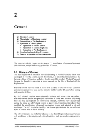
![C
Ch
ha
ap
pt
te
er
r 2
2 –
– C
Ce
em
me
en
nt
t 10
School of Petroleum Engineering, UNSW Open Learning - 2000
2.2 Manufacture of Portland Cement
The manufacturing process for Portland cement is shown in Fig. 2.1. This is a process
in which raw materials are ground, mixed and subjected to the extreme temperature of
the kiln (2600 to 28000
F) to produce compounded oxides, resulting in granules of
cement clinker upon cooling. After aging in storage, the seasoned clinker is taken to
the clinker grinding mills where gypsum (CaSO4.2H20) is added to retard setting time
and increase ultimate strength. The manufacturing process is described in more detail
below.
(1 cup crushed)
Limestone
Oyster Shells
Marl
(1/2 cup pulverised)
Clay or Shale
& Iron Ore
+ Heat (2600 - 3000 oF)
Clinker
+
Gypsum
+
Grinding
3 CaO.SiO2
Tricalcium Silicate
2 CaO.SiO2
Dicalcium Silicate
3 CaO.Al2O3
Tricalcium Aluminate
4 CaO.Al2O3.FeO3
Tetracalcium Aluminoferrite
[CaO] [SiO2.Al2O3.Fe2O3]
Raw Materials for Portland Cement
Fig. 2.1 - Manufacture of Portland cement.
Raw materials are found in quarries of calcareous and argillaceous rock, or
subproducts which contain these materials.
q Calcareous materials: contain calcium carbonate (CaCO3) or calcium oxide
(CaO). They include limestone, cement rock, chalk, marl and alkali waste
(from chemical plants).
q Argillaceous materials: contain clay or clay materials. They include clay,
shale, slate and ash.
There are generally two processes of preparing the raw blends: dry and wet. The
difference between them lies in the technique used to separate the unwanted minerals
from the raw materials, in order to obtain the desired initial composition.
q DRY PROCESS - clays and limestone minerals are fed to separate batteries of
crushers. The finely crushed products are stored in separate bins and their
composition analyzed. Chemists blend rock from different bins to achieve the
desired composition. The blend is then transferred to a grinder, where it is
pulverized to a mesh size of 100-200 in order to maximize the contact between
the particles (Fig. 2.2).](data:image/gif;base64,R0lGODlhAQABAIAAAAAAAP///yH5BAEAAAAALAAAAAABAAEAAAIBRAA7)