
Recommended
Recommended
More Related Content
What's hot
What's hot (19)
Similar to Hip Retractor Metal-to-Plastic Case Study
Similar to Hip Retractor Metal-to-Plastic Case Study (20)
Recently uploaded
Recently uploaded (20)
Hip Retractor Metal-to-Plastic Case Study
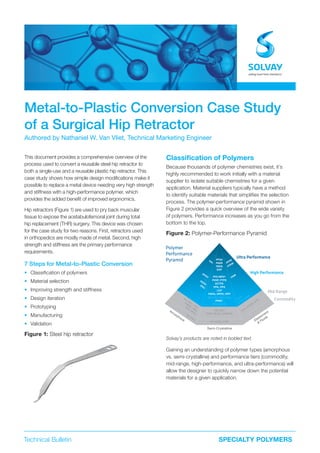
- 1. Technical Bulletin SPECIALTY POLYMERS Metal-to-Plastic Conversion Case Study of a Surgical Hip Retractor Authored by Nathaniel W. Van Vliet, Technical Marketing Engineer This document provides a comprehensive overview of the process used to convert a reusable steel hip retractor to both a single-use and a reusable plastic hip retractor. This case study shows how simple design modifications make it possible to replace a metal device needing very high strength and stiffness with a high-performance polymer, which provides the added benefit of improved ergonomics. Hip retractors (Figure 1) are used to pry back muscular tissue to expose the acetabulofemoral joint during total hip replacement (THR) surgery. This device was chosen for the case study for two reasons. First, retractors used in orthopedics are mostly made of metal. Second, high strength and stiffness are the primary performance requirements. 7 Steps for Metal-to-Plastic Conversion • Classification of polymers • Material selection • Improving strength and stiffness • Design iteration • Prototyping • Manufacturing • Validation Figure 1: Steel hip retractor Classification of Polymers Because thousands of polymer chemistries exist, it’s highly recommended to work initially with a material supplier to isolate suitable chemistries for a given application. Material suppliers typically have a method to identify suitable materials that simplifies the selection process. The polymer-performance pyramid shown in Figure 2 provides a quick overview of the wide variety of polymers. Performance increases as you go from the bottom to the top. Figure 2: Polymer-Performance Pyramid Solvay’s products are noted in bolded text. Gaining an understanding of polymer types (amorphous vs. semi-crystalline) and performance tiers (commodity, mid-range, high-performance, and ultra-performance) will allow the designer to quickly narrow down the potential materials for a given application. PC, PPC, COC PMMA, ABS PS, PVC PBT, PET POM, PA 6.6, UHMWPE PP, HDPE, LDPE EVA, EPDM , EPR PVC Alloys FFKMPFPE PPSU PESU PSU TPI PAEK PFSA PEEK EAP XLPO-HFFR XLPO FKMPFA/MFA® PVDF, PTFE ECTFE PPA, PPS LCP PARA, HPPA, HPP Specialty Polyamides PVDC PEX & XLPE PEI PAI PI Amorphous Elastomers & Fluids Semi-Crystalline Polymer Performance Pyramid Ultra Performance High Performance Mid Range Commodity
- 2. 2 Metal-to-Plastic Conversion of a Surgical Hip Retractor Amorphous vs. Semi-crystalline Polymers Thermoplastics are comprised of repeating units that form long chains. Inherent characteristics of these chains may or may not allow for the formation of crystalline structures within the material. An amorphous material is one without the formation of crystals, while a semi-crystalline material has both amorphous and crystalline regions. Figure 3 illustrates the co-existence of amorphous and crystalline phases in a semi-crystalline polymer. Table 1 gives an overview of how amorphous polymer properties typically change when crystalline regions are allowed to form. Figure 3: Amorphous and crystalline regions in semi-crystalline polymers Macro- molecule Crystalline zone Amorphous zone Performance Tiers Polymer performance increases in one or more properties as you move from the bottom to the top of the performance pyramid. Each tier can be associated with certain performance expectations: • Commodity polymers typically have baseline properties. For example, high-density polyethylene (HDPE) is neither superior nor inferior across most performance categories. • Mid-range polymers (also referred to as engineering polymers) typically excel in one or two performance categories. For example, polyamides (PA/Nylon) are known for their exceptional strength and stiffness. Polycarbonate (PC) is known for its transparency and toughness. • High-performance polymers outperform mid- range polymers and are often improved variants of mid-range polymers. For example, polyarylamide (PARA) improves the strength, stiffness, chemical resistance, and moisture resistance of PA 6.6 through monomer enhancement. Polyphenylsulfone (PPSU) offers increased chemical resistance and thermal performance compared to PC by incorporating higher performance monomers. • Ultra-performance polymers excel in most, if not all, performance categories, and they offer varying combinations of these superlative properties. For example, polyetheretherketone (PEEK) exhibits an excellent balance of mechanical, thermal, and chemical performance, and it’s easier to process than many other high- and ultra-performance polymers. Requirements for Medical Devices Medical applications often require high performance across multiple performance categories. Particularly challenging for most polymers is the need for high chemical resistance (due to exposure to aggressive cleaners and disinfectants) and the ability to withstand a variety of sterilization techniques (such as steam sterilization or a large dose of gamma radiation). Many material suppliers offer a selection of polymer chemistries suitable for medical applications, which are commonly referred to as medical-grade polymers. Table 2 presents appropriate usage scenarios and graded performance for a selection of Solvay’s medical-grade polymers. Table 1: Typical property changes due to polymer crystallization Property Amorphous Amorphous & Crystalline Transparency Common Uncommon Strength/stiffness Nominal Increased Ductility Nominal Decreased Fatigue resistance Nominal Increased Dimensional stability Nominal Decreased Chemical resistance Nominal Increased
- 3. 3 Metal-to-Plastic Conversion of a Surgical Hip Retractor Table 2: Usage scenario for select Solvay medical-grade polymers Properties KetaSpire® PEEK AvaSpire® PAEK Radel® PPSU Udel® PSU Ixef® PARA Performance tier Ultra Performance Ultra Performance High Performance High Performance High Performance Chemistry type Semi-crystalline Semi-crystalline Amorphous Amorphous Semi-Crystalline Typical usage Reusable Reusable Reusable Single-use Single-use Cost $$$$ $$$ $$ $$ $ Transparency No No Optional Optional No Strength/stiffness A B C C A+ Ductility B A A+ A C Fatigue resistance A+ B C C A Dimensional stability B B+ A A B Chemical resistance A+ A A B B A = Excellent, B = Good, C = Satisfactory Enhancing Performance with Additives and Fillers Polymer performance can be further modified by incorporating additives and fillers. Additives, such as coloring pigments, color stabilizers, and processing aids, are commonly used in small quantities. For example, a color pigment loading ≤ 5 % is typically sufficient to obtain most colors without affecting mechanical properties. Fillers are often incorporated in large quantities (10 to 60 %) and typically modify or reinforce mechanical properties. Glass-fiber reinforcement is a commonly used filler in the medical industry. Table 3 presents a comparison of typical material properties before and after the addition of glass-fiber reinforcement. Table 3: Effects of glass-fiber reinforcement Properties Unreinforced Glass-fiber Reinforced Transparency Possible Opaque Strength/stiffness Nominal Greatly increased Ductility Nominal Greatly decreased Fatigue resistance Nominal Increased Dimensional stability Nominal Dependent on fiber orientation Material Selection A list of boundary conditions can be used to narrow the list of materials suitable for a given application. Table 4 presents a list of boundary conditions for both single-use and reusable versions of the hip retractor. Table 4: Hip retractor boundary conditions Properties Single-use Reusable Sterilization 100 kGy gamma dose 1,000+ cycles steam Strength/stiffness Very important Very important Fatigue resistance Less important Very important Chemical resistance Less important Very important Material cost Very important Less important Single-use hip retractor In this case study, material selection for a single-use device assumes that the medical device will be sterilized with a gamma dosage between 40 and 100 kGy. Steam sterilization is not a requirement, though a single flash steam sterilization cycle or a wipe-down with a chemical cleaner in the operating theater is not uncommon. As shown in Table 2, Ixef® PARA meets or exceeds all requirements and is a cost-efficient. The addition of glass- fiber reinforcement (Table 3) further enhances desired properties. Ixef® GS 1022 is a 50% glass-filled PARA grade that meets these requirements. GS grades are gamma-stabilized materials and are available in variety of colors. Reusable hip retractor In this case study, material selection for a reusable device assumes up to 1,000 cycles of steam sterilization and repeated exposure to cleaning agents. Fatigue resistance is required in order to maintain mechanical properties over time. Note that when designing a reusable medical device, it is important to use data generated after the specified usage scenario (such as after 1,000 autoclave cycles). This data should be available through the material supplier. Referring to Table 2, AvaSpire® polyaryletherketone (PAEK) is the lowest cost material that meets or exceeds
- 4. 4 Metal-to-Plastic Conversion of a Surgical Hip Retractor Despite being one of the stiffest medical-grade plastics in the industry, Ixef® GS 1022 exhibits a tensile modulus that is 1/9th that of 17-4 steel. A particularly effective method for improving a part’s stiffness is to modify the area moment of inertia. In order to match the performance of steel, the plastic part will need to be larger. The following two examples help put this concept into perspective. Example 1: Rectangular geometry Using a hip retractor is similar to using a cantilever beam, which is shown in Figure 4 with a rectangular cross- section. Figure 4: Cantilever beam with rectangular cross- section An input force (F) deflects the cantilever beam a distance of Y. The resulting deflection is inversely related to the tensile modulus of the material (E) and the area moment of inertia (I). Table 6 presents the theoretical deflection (Y) resulting from an input force (F = 1 N), bar width (w = 2.5 cm), bar thickness (t = 0.5 cm) and beam length (L = 40 cm). These dimensions are similar to that of the steel hip retractor. Table 6: Theoretical results of rectangular cantilever beam loading, constant thickness Properties AvaSpire® AV-651 GF30 Ixef® GS 1022 17-4 Steel Beam thickness, t 0.5 cm 0.5 cm 0.5 cm Deflection, Y 3.10 cm 1.4 cm 0.16 cm Ixef® PARA and AvaSpire® PAEK deflected approximately 10 x and 20 x that of 17-4 steel, respectively. The large difference between plastic and steel is attributed to the deflection being inversely proportional to the material’s tensile modulus. It is assumed that the deflection of the plastic retractor needs to match the deflection of the steel retractor. Table 7 presents the theoretical thickness (t) of a cantilever beam needed to obtain an identical deflection for all three materials. Table 7: Theoretical results of rectangular cantilever beam loading, constant deflection Result AvaSpire® AV-651 GF30 Ixef® GS 1022 17-4 Steel Beam thickness, t 1.35 cm 1.04 cm 0.5 cm Deflection, Y 0.16 cm 0.16 cm 0.16 cm To compensate for a deflection 10 x and 20 x that of the steel beam, Ixef® PARA and AvaSpire® PAEK needed to increase their thicknesses by only 2.1 x and 2.7 x, respectively. Note that even though the thickness of the plastic beams are greater than that of the steel beam, the resulting weight of the plastic beams will be 1/2 x and 1/3 x that of the steel beam. Metal-to-plastic conversion typically trades lower weight for increased volume. Y F L Y = FL3 8EI t b bt3 12 I = nat hs c d b x A = bd – h (b – t ) 2 2 2b3s + ht3 I = – A ( b – c )2 all of these requirements. The addition of glass-fiber reinforcement can be used to further improve required properties. AvaSpire® AV-651 GF30 is a 30 % glass-filled PAEK grade that meets these requirements. Improving Strength and Stiffness The most challenging obstacle to overcome when converting the steel retractor to plastic is a large drop in tensile modulus (stiffness). Table 5 presents a comparison of applicable properties for Ixef® GS 1022, AvaSpire® AV- 651 GF30, and 17-4 (PH-a) stainless steel. Table 5: Mechanical properties applicable to hip retractor (ASTM D638) Properties Units AvaSpire® AV-651 GF30 Ixef® GS 1022 17-4 Steel Tensile strength at break MPa (psi) 156 (22,600) 265 (38,400) ~ 1,000 (145,000)* Tensile modulus at break GPa (ksi) 9.9 (1,430) 22 (3,190) ~ 197 (28,570) Tensile elongation at break % 2.9 1.8 ~ 0.5% Specific gravity g/cm3 1.52 1.78 7.80 * At yield
- 5. 5 Metal-to-Plastic Conversion of a Surgical Hip Retractor Example 2: Ribbed geometry Adding ribs, another common method for increasing stiffness, can be achieved by using a U-beam geometry (Figure 5). It is assumed that the rectangular geometry without ribs (Example 1) will remain unchanged for 17-4 steel (x = 0). Table 8 presents the length of ribbing (x) needed in order for AvaSpire® AV-651 GF30 and Ixef® GS 1022 to match the performance of the steel beam. This demonstrates that plastic can mimic the stiffness of steel through simple design modifications. This type of modification will be used in the metal-to-plastic conversion of the hip retractor. Figure 5: U-beam cross-section Table 8: Rib length with fixed diameter Result AvaSpire® AV-651 GF30 Ixef® GS 1022 17-4 Steel Rib length 1.11 cm 0.73 cm No Ribs Deflection, Y 0.16 cm 0.16 cm 0.16 cm Design Iterations Designing with Computer Aided Engineering The design of the plastic hip retractor was largely performed using computer aided engineering (CAE). SOLIDWORKS® was used for modeling and SOLIDWORKS® Simulation was used for mechanical testing. First, it was necessary to virtualize the real-world performance of the steel hip retractor. The primary concern was the deflection of the hip retractor’s tip with respect to the handle area. A test rig was used to measure the performance of the steel retractor under real- life conditions, and the test was repeated in a simulated environment. Figure 6 presents a comparison of the results, which are similar. Figure 6: Steel retractor performance mapping The same design was used to make a single-use retractor (Ixef® PARA) and a reusable retractor (AvaSpire® PAEK). Because Ixef® GS 1022 offers 50 % greater stiffness than AvaSpire® AV-651 GF30, the single-use retractor was designed to be approximately 25 % stiffer than the steel retractor and the reusable retractor to be approximately 25 % less stiff than the steel retractor. This allowed for the production of two different retractors using only one design. bt3 12 = nat hs c d b x A = bd – h (b – t ) c = b – 2b2s + ht2 2A 2b3s + ht3 3 I = – A ( b – c )2 Inputload[N] Deflection [cm] Linear (Simulation/17-4 steel) Linear (Real life/17-4 steel) 0 10 20 30 40 50 60 70 0.0 0.5 1.0 1.5 2.0 2.5 3.0
- 6. 6 Metal-to-Plastic Conversion of a Surgical Hip Retractor Initial Design The goal of the initial design was to demonstrate that the Ixef® PARA single-use retractor and the AvaSpire® PAEK reusable retractor could attain the stiffness of the steel retractor. Keeping the first design as simple as possible is recommended, which in this case entailed adding ribs to the upper surface of the steel retractor. Figure 7 shows a side-by-side comparison of CAD models for the initial plastic retractor design and the steel retractor. The size of the plastic ribs were repeatedly modified and tested until the Ixef® PARA single-use design and the AvaSpire® PAEK reusable design achieved 125 % and 75 % of the metal retractor’s stiffness, respectively. This marked the achievement of the goal for the first design. Figure 7: Initial plastic hip retractor design Plastic provides more design freedom The goal of the second plastic design was to create a retractor that took full advantage of the design freedom made possible by using plastic. In this design, a large handle was added to improve the look and ergonomics. The rigidity of the thicker handle provided the stiffness required at the back-end of the retractor. The design improvement allowed a smaller, rounder geometry to be used for the front-end of the retractor. Figure 8 presents a comparison of CAD models through the second plastic design. Figure 8: Second plastic hip retractor design FEA analysis of the final design again predicted that AvaSpire® AV-651 GF30 and Ixef® GS 1022 would achieve a stiffness 0.75 x and 1.25 x that of the steel retractor, respectively. The design was 3D printed using SLS and then assessed by the project team. Based on feedback, the width of the handled was reduced by 20 %. Finite element analysis (FEA) of the second plastic design predicted that AvaSpire® AV-651 GF30 and Ixef® GS 1022 would possess a stiffness of 0.75 x and 1.25 x the steel retractor, respectively. The conceptualized model was then realized by 3D printing via selective laser sintering (SLS). Solicited feedback was positive regarding the general form of the hip retractor, indicating a successful second design. Final Design While the general form and performance of the second plastic retractor design was on track, the look and ergonomics required additional work. The assistance of an industrial design company was enlisted to conceptualize unique variations for a plastic retractor. Figure 9 shows the sketch provided. The final design of the plastic incorporated these design features and is shown in Figure 10. Figure 9: Hip retractor concept Figure 10: Final plastic hip retractor design First plastic design First plastic design First plastic design Second plastic design Second plastic design Final plastic design Steel Steel Steel
- 7. 7 Metal-to-Plastic Conversion of a Surgical Hip Retractor Prototyping Prototyping is recommended to evaluate the feel and/or performance of a design before incurring the full cost of manufacturing. For best results, the prototyping process should start during the design phase, as demonstrated in this case study. Note that more than one prototyping method may be appropriate. In the case of the plastic hip retractor, the primary goal was to examine how the retractor felt when held. Additive Manufacturing 3D printing is one of the fastest methods for obtaining a physical copy of a design. The most common types include selective laser sintering (SLS), stereolithography (SLA), and fused filament fabrication (FFF). The material supplier or processor should be able to recommend the most appropriate method for a given application. Parts produced with 3D printing allow for an effective evaluation of ergonomics. The disadvantages of additive manufacturing include reduced mechanical performance and a limited offering of high- and ultra-performance materials. Therefore, the use of additive manufacturing for verifying the part’s mechanical performance is not recommended. All iterations of the hip retractor were printed out of PA 6 using the SLS method to evaluate ergonomics. Machining Machining is another quick and effective method for creating a to-scale part, and permits an effective evaluation of ergonomics. Unreinforced (neat) polymers can be used for validating the mechanical performance of the design; however, reinforced polymers contain non- uniform fiber orientation, which skews the mechanical performance of the part. Machining was not used in the design process of the hip retractor. However, machined samples of alternative handle types were made for demonstration purposes. Short-run Injection Molding Prototype tooling is considerably slower than additive or subtractive manufacturing. Production injection molds for high- and ultra-performance polymers are typically produced using high quality steels (P20, S7, H13), which can withstand high processing temperatures and resist abrasion from certain additives and fillers. The same tool can also be made using a less costly and/or easier- to- cut steel or aluminum. A prototype tool typically lasts for at least a few hundred cycles. A prototype mold was not used for the plastic hip retractor due to the high level of confidence in the accuracy of the CAE results. Manufacturing Surgical instruments are most commonly manufactured by machining and injection molding. For the purpose of this study, cost estimations assumed producing 3,500 hip retractors over a 3-year span. The plastic material cost for equal portions of Ixef® PARA and AvaSpire® PAEK used during this time is approximately $ 30,000, which includes a 25 % inflation to account for scrap and trial runs. For reference, the stamped steel hip retractor was purchased for about $ 350. Machining Machining is well-suited for low-volume production. It provides a quick turnaround times and requires nominal up-front cost. Factors to consider include: Pros • Efficient for small volumes • Fast turnaround times for small volumes • Design change flexibility • Undercuts and threads are easy to produce Cons • Inefficient for large volumes • Slow turnaround time for large volumes • Fiber-reinforced plastics yield non-optimal properties • Relies on stock shape supply from secondary processor • Complex geometries significantly increase cost • Material scrap rates can be high Because the geometry of the plastic hip retractor is fairly intricate, the estimated cost is $ 145 per part for 100 devices and $ 125 per part for 10,000 devices, not including material. The cost to machine 3,500 retractors over three years would be in excess of $ 500,000, which translates to about $ 150 for each single-use Ixef® PARA retractor and $ 160 for each reusable AvaSpire® PAEK retractor. Based on these numbers, machining is clearly not economical. Injection Molding Injection molding is a manufacturing process that forces molten plastic into a custom mold design, and it is well-suited for high-volume production. This method also provides quick turnaround times, but requires considerably more time and up-front cost to cover the purchase of a molding machine and tooling for production. Factors to consider include: Pros • Efficient for large volumes • Fast turnaround time for large volumes • Complex geometries incorporated cost-effectively • Fiber-reinforced plastics yield optimal properties • Relies on resin supply from material supplier • Low material scrap rates
- 8. 8 Metal-to-Plastic Conversion of a Surgical Hip Retractor Cons • Inefficient for small volumes • Little design change flexibility • Threads, undercuts, and cores can be challenging • Potential issues with residual stress and/or knit lines A key advantage of this method is using family molds, which are single molds that produce multiple parts simultaneously. Injection molding provides a high level of design flexibility by using interchangeable inserts to produce variations of the part while using the same mold. The hip retractor mold incorporated interchangeable inserts to allow for alternative handle design. The size of the tool was doubled to allow for future projects. The material required for the mold is H13, which is one of the highest quality mold steels available. Figure 11 presents the CAD drawing of the proposed tool, which was quoted at $ 38,000. The combined cost of the material, mold, and processing was approximately $ 100,000, which translates to about $ 10 for each single-use Ixef® PARA retractor and $ 18 for each reusable AvaSpire® PAEK retractor. Being that this is one-fifth the cost of machining, injection molding was selected as the manufacturing method. Figure 11: Hip retractor tool with interchangeable handle Figure 12 shows the predicted warpage and fiber orientation when the mold is gated in the center of the device at the end of the handle. These predictions were used to reinforce confidence in the mold design’s ability to produce parts and show that the molded part would have minimal warpage and uniform fiber orientation. Figure 12: Simulated results when gating at center of retractor Injection molding simulation Tooling cost can range from $ 1,000 to $ 500,000 depending on size and features. Before incurring this expense, it is recommended to use a processing simulator, such as Autodesk Moldflow® , to test the mold design to predict any processing issues that may arise. As a typical analysis can have hundreds of inputs and outputs, designers should rely on the processor, mold- maker, and/or material supplier to perform this type of analysis. Solvay provides Moldflow® and structural analyses free of charge. Program conversion cost It is not always the case that a metal-to-plastic conversion contains a single instrument. In another recent case study, an OEM was interested in converting a large portion of a program from steel to plastic. The program consisted unit having 200 parts per stock keeping unit (SKU) and it produced approximately 200 SKUs per year. Analysis showed that the average cost of steel parts were $ 98/each, while the average cost of injection molding reusable plastic parts would be $ 23/each. The estimated cost for purchasing the molds was $ 2,000,000, which may seem daunting until weighed against the potential savings. The cost to produce 200 SKUs, each having 200 metal parts, was about $ 3,920,000 per year. By converting to plastic parts, the cost would be reduced to about $ 920,000 per year. Based on this, tooling cost would be recovered in 8 months, after which a savings of $ 3,000,000 per 200 SKUs would be possible for the remainder of the program’s life.
- 9. Safety Data Sheets (SDS) are available by emailing us or contacting your sales representative. Always consult the appropriate SDS before using any of our products. Neither Solvay Specialty Polymers nor any of its affiliates makes any warranty, express or implied, including merchantability or fitness for use, or accepts any liability in connection with this product, related information or its use. Some applications of which Solvay’s products may be proposed to be used are regulated or restricted by applicable laws and regulations or by national or international standards and in some cases by Solvay’s recommendation, including applications of food/feed, water treatment, medical, pharmaceuticals, and personal care. Only products designated as part of the Solviva® family of biomaterials may be considered as candidates for use in implantable medical devices. The user alone must finally determine suitability of any information or products for any contemplated use in compliance with applicable law, the manner of use and whether any patents are infringed. The information and the products are for use by technically skilled persons at their own discretion and risk and does not relate to the use of this product in combination with any other substance or any other process. This is not a license under any patent or other proprietary right. All trademarks and registered trademarks are property of the companies that comprise Solvay Group or their respective owners. © 2017 Solvay Specialty Polymers. All rights reserved. D 06/2017 | Version 1.0 Design by ahlersheinel.com SpecialtyPolymers.EMEA@solvay.com | Europe, Middle East and Africa SpecialtyPolymers.Americas@solvay.com | Americas SpecialtyPolymers.Asia@solvay.com | Asia Pacific www.solvay.com Validation Single-use and reusable versions of the hip retractor were submitted for testing using the same method utilized to map the steel retractor’s performance during the beginning of the design phase. Figure 13 presents the resulting deflection when the retractor’s handle was fixed and a load was applied to the retractor’s tip. The Ixef® GS 1022 single-use retractor proved be slightly stiffer than the steel retractor, and AvaSpire® AV-651 GF30 reusable retractor was slightly less stiff than the steel retractor. Both versions of the plastic retractor weighed approximately 50% less than the steel retractor, thereby significantly reducing the weight added to a surgical tray Figure 13: Resulting deflection of plastic and metal hip retractors Conclusions It was successfully demonstrated that steel and plastic retractors can exhibit comparable mechanical performance. The end-user purchase price of the metal retractor was approximately $350. The end-user cost of the plastic retractors, assuming a 100% markup for single-use and 1,000% markup for reusable, would be $20 and $180, respectively. This demonstrates the significant economic advantage of plastic over metal. Designing in plastic also enables the OEM to sell single- use instrumentation, which is rarely economical using metal. Resources for designing with plastics are expanding within the medical industry. Plastic material suppliers are increasing focus on the medical industry, adding resources to aid in plastic adoption and metal-to- plastic conversion. Processors who traditionally worked exclusively with metals are adopting and gaining expertise with plastic manufacturing methods. OEMs are hiring designers with a backgrounds either partially or fully involving plastics. With quickly increasing healthcare prices and improving technology, designers across the medical industry are learning to increase performance and decrease costs through the utilization of specialty plastics. Deflection [cm] Inputload[N] 0 10 20 30 40 50 0.0 0.5 1.0 1.5 2.0 2.5 Linear (Ixef® 1022) Linear (17-4 steel) Linear (AvaSpire® AV-651 GF30)