SlideShare a Scribd company logo
1 of 58
Download to read offline
Embedded Controller A E C - 6 8 5 0
AEC-6850
Fanless Embedded Control PC
Intel®
Celeron®
M 600MHz
1.3GHz Processor
With Ethernet, 2 COMs, Audio
TV-out, CompactFlash•
AEC-6850 Manual 2nd Ed.
August 2007
Downloaded from www.Manualslib.com manuals search engine
www.ipc247.com - maytinhaaeon.com
Embedded Controller A E C - 6 8 5 0
i
Copyright Notice
This document is copyrighted, 2007. All rights are reserved. The
original manufacturer reserves the right to make improvements to
the products described in this manual at any time without notice.
No part of this manual may be reproduced, copied, translated, or
transmitted in any form or by any means without the prior written
permission of the original manufacturer. Information provided in
this manual is intended to be accurate and reliable. However, the
original manufacturer assumes no responsibility for its use, or for
any infringements upon the rights of third parties that may result
from its use.
The material in this document is for product information only and is
subject to change without notice. While reasonable efforts have
been made in the preparation of this document to assure its
accuracy, AAEON assumes no liabilities resulting from errors or
omissions in this document, or from the use of the information
contained herein.
AAEON reserves the right to make changes in the product design
without notice to its users.
Downloaded from www.Manualslib.com manuals search engine
Embedded Controller A E C - 6 8 5 0
ii
Acknowledgments
x Award is a trademark of Award Software International, Inc.
x CompactFlash™
is a trademark of the Compact Flash
Association.
x Intel®
and Celeron®
M are trademarks of Intel®
Corporation.
x Microsoft Windows
®
is a registered trademark of Microsoft
Corp.
x PC/AT, PS/2, and VGA are trademarks of International
Business Machines Corporation.
All other product names or trademarks are properties of their
respective owners.
Downloaded from www.Manualslib.com manuals search engine
Embedded Controller A E C - 6 8 5 0
iii
Packing List
Before you begin operating your PC, please make sure that the
following materials have been shipped:
z 1 AEC-6850 Embedded Control PC
z 1 Keyboard  mouse cable
z 1 AC Power Adapter (AC version only, A1/A2
Version)
z 1 Phoenix Power Connector (DC version only,
A3/A4 Version)
z 2 Wallmount Brackets
z 1 Audio Cable
z 1 Screw Package
z 1 CD-ROM for manual (in PDF format) and
drivers
If any of these items should be missing or damaged, please
contact your distributor or sales representative immediately.
Downloaded from www.Manualslib.com manuals search engine
Embedded Controller A E C - 6 8 5 0
iv
Safety  Warranty
1. Read these safety instructions carefully.
2. Keep this user's manual for later reference.
3. Disconnect this equipment from any AC outlet before cleaning. Do
not use liquid or spray detergents for cleaning. Use a damp cloth.
4. For pluggable equipment, the power outlet must be installed near
the equipment and must be easily accessible.
5. Keep this equipment away from humidity.
6. Put this equipment on a firm surface during installation. Dropping
it or letting it fall could cause damage.
7. The openings on the enclosure are for air convection. Protect the
equipment from overheating. DO NOT COVER THE OPENINGS.
8. Make sure the voltage of the power source is correct before
connecting the equipment to the power outlet.
9. Position the power cord so that people cannot step on it. Do not
place anything over the power cord.
10. All cautions and warnings on the equipment should be noted.
11. If the equipment is not used for a long time, disconnect it from the
power source to avoid damage by transient over-voltage.
12. Never pour any liquid into an opening. This could cause fire or
electrical shock.
13. Never open the equipment. For safety reasons, only qualified
service personnel should open the equipment.
14. If any of the following situations arises, get the equipment
checked by service personnel:
a. The power cord or plug is damaged.
b. Liquid has penetrated into the equipment.
c. The equipment has been exposed to moisture.
Downloaded from www.Manualslib.com manuals search engine
Embedded Controller A E C - 6 8 5 0
v
d. The equipment does not work well, or you cannot get it
to work according to the user’s manual.
e. The equipment has been dropped and damaged.
f. The equipment has obvious signs of breakage.
15. DO NOT LEAVE THIS EQUIPMENT IN AN ENVIRONMENT
WHERE THE STORAGE TEMPERATURE IS BELOW -20°C
(-4°F) OR ABOVE 60°C (140°F). IT MAY DAMAGE THE
EQUIPMENT.
FCC Safety
This device complies with Part 15 FCC Rules.
Operation is subject to the following two
conditions: (1) this device may not cause
harmful interference, and (2) this device must
accept any interference received including
interference that may cause undesired
operation.
Caution:
There is a danger of explosion if the battery is incorrectly
replaced. Replace only with the same or equivalent type
recommended by the manufacturer. Dispose of used batteries
according to the manufacturer’s instructions and your local
government’s recycling or disposal directives.
Downloaded from www.Manualslib.com manuals search engine
Embedded Controller A E C - 6 8 5 0
vi
Below Table for China RoHS Requirements
ѻકЁ᳝↦᳝ᆇ⠽䋼៪‫ܗ‬㋴ৡ⿄ঞ৿䞣
AAEON Boxer/ Industrial System
᳝↦᳝ᆇ⠽䋼៪‫ܗ‬㋴
䚼ӊৡ⿄ 䪙
(Pb)
∲
(Hg)
䬝
(Cd)
݁Ӌ䫀
(Cr(VI))
໮⒈㘨㣃
(PBB)
໮⒈Ѡ㣃
䝮(PBDE)
ॄࠋ⬉䏃ᵓ
ঞ݊⬉ᄤ㒘ӊ
h ƻ ƻ ƻ ƻ ƻ
໪䚼ֵো
䖲᥹఼ঞ㒓ᴤ
h ƻ ƻ ƻ ƻ ƻ
໪໇ h ƻ ƻ ƻ ƻ ƻ
Ё༂໘⧚఼
Ϣ‫ݙ‬ᄬ
h ƻ ƻ ƻ ƻ ƻ
⹀Ⲭ h ƻ ƻ ƻ ƻ ƻ
⬉⑤ h ƻ ƻ ƻ ƻ ƻ
O˖㸼⼎䆹᳝↦᳝ᆇ⠽䋼೼䆹䚼ӊ᠔᳝ഛ䋼ᴤ᭭Ёⱘ৿䞣ഛ೼
SJ/T 11363-2006 ᷛ‫ޚ‬㾘ᅮⱘ䰤䞣㽕∖ҹϟDŽ
X˖㸼⼎䆹᳝↦᳝ᆇ⠽䋼㟇ᇥ೼䆹䚼ӊⱘᶤϔഛ䋼ᴤ᭭Ёⱘ৿䞣䍙ߎ
SJ/T 11363-2006 ᷛ‫ޚ‬㾘ᅮⱘ䰤䞣㽕∖DŽ
໛⊼˖
ϔǃℸѻક᠔ᷛ⼎П⦃ֱՓ⫼ᳳ䰤ˈ㋏ᣛ೼ϔ㠀ℷᐌՓ⫼⢊‫މ‬ϟDŽ
ѠǃϞ䗄䚼ӊ⠽䋼Ё༂໘⧚఼ǃ‫ݙ‬ᄬǃ⹀Ⲭǃ⬉⑤Ў䗝䌁કDŽ
Downloaded from www.Manualslib.com manuals search engine
Embedded Controller A E C - 6 8 5 0
vii
Contents
Chapter 1 General Information
1.1 Introduction................................................................ 1-2
1.2 Features .................................................................... 1-4
1.3 Specifications ............................................................ 1-5
Chapter 2 Hardware Installation
2.1 Dimension ................................................................. 2-2
2.2 SDRAM Installation ................................................... 2-3
2.3 Internal CF Card Installation (IDE interface CF slot for
boot up) ........................................................................... 2-4
2.4 COM2 RS-232/422/485 Setting ................................ 2-6
2.5 COM2 RS-232/422/485 Serial Port Connector......... 2-6
2.6 COM 1 RS-232 Serial Port Connector ...................... 2-6
2.7 CD-ROM and 2.5” HDD Kit Installation..................... 2-7
2.8 Dual 2.5” HDD Kit Installation ................................... 2-11
2.9 3.5” HDD Kit Installation............................................ 2-15
2.10 Wallmount Bracket Installation................................ 2-19
Chapter 3 Award BIOS Setup
3.1 System Test and Initialization. .................................. 3-2
3.2 Award BIOS Setup .................................................... 3-3
Chapter 4 Driver Installation
4.1 Installation ................................................................. 4-3
Downloaded from www.Manualslib.com manuals search engine
Embedded Controller A E C - 6 8 5 0
viii
Appendix A Programming The Watchdog Timer
A.1 Programming ........................................................A-2
A.2 ITE8712 Watchdog Timer Initial Program ............A-6
Appendix B I/O Information
B.1 I/O Address Map ..................................................B-2
B.2 1st
MB Memory Address Map ...............................B-2
B.3 IRQ Mapping Chart ..............................................B-3
B.2 DMA Channel Assignments .................................B-3
Downloaded from www.Manualslib.com manuals search engine
Embedded Controller A E C - 6 8 5 0
Chapter 1 General Information 1- 1
General
Chapter
1
Information
Downloaded from www.Manualslib.com manuals search engine
Embedded Controller A E C - 6 8 5 0
Chapter 1 General Information 1-2
1.1 Introduction
Due to the growing popularity from the IPC market, the newest
Boxer series AEC-6850 has been introduced by AAEON.
Compared with the AEC-6830, it is an advanced version because it
utilizes an Intel®
Celeron®
processor without a fan.
New Innovation for Entertainment Multimedia Domain
In this era of information explosion, the advertising of consumer
products will not be confined to the family television, but will also
spread to high-traffic public areas, like department stores, the bus,
transportation station, the supermarket etc. The advertising
marketing industry will resort to every conceivable means to
transmit product information to consumers. System integrators
will need a multifunction device to satisfy commercial needs for
such public advertising.
Being a control center, the AEC-6850 is suitable for public
multimedia entertainment services. Equipped with a high efficiency
heat conduction mechanism, which is patented in Germany, the
AEC-6850 supports up to Celeron
®
M 1.3GHz processor.
The AEC-6850 is compact in size but has attractive and flexible
extension capabilities such as a 4-in-one card reader, 3 USB2.0
ports, VGA, TV-out, DVI, Audio, 2 COM ports and an optional IEEE
1394(FireWire) port.
Downloaded from www.Manualslib.com manuals search engine
Embedded Controller A E C - 6 8 5 0
Chapter 1 General Information 1- 3
Stable Design for Rugged Environment
The AEC-6850 is designed for rugged environments due to the
following reasons; first, it can withstand tough vibration testing up to
5G rms. With the anti-vibration hard drive device option, the
AEC-6850 can be used in high vibration environments. In addition,
the AEC-6850 offers low power consumption system that while
operating in ambient temperatures ranging from -15° to 60°C. The
MTBF(Mean Time Before Failure) rating states that the AEC-6850
can operate up to 50,000 hours at 35°C ambient temperature,
which indicates its careful and long-life design.
The AEC-6850 is a standalone high performance controller
designed for long-life operation and with high reliability. It can
replace traditional methods and become the mainstream
controller for the multimedia entertainment market.
Downloaded from www.Manualslib.com manuals search engine
Embedded Controller A E C - 6 8 5 0
Chapter 1 General Information 1-4
1.2 Features
x Fanless Design with Intel®
Celeron®
M 600MHz / 1.3GHz
Processor
x 4 in 1 Card Reader
x 2 COM / S-video / 3 USB 2.0 / Ethernet
Downloaded from www.Manualslib.com manuals search engine
Embedded Controller A E C - 6 8 5 0
Chapter 1 General Information 1- 5
1.3 Specifications
System
z CPU: Intel®
Celeron®
M 600MHz/ 1.3GHz
Processor
z Construction: Rugged Aluminum Alloy chassis
z System Memory: DDR SODIMM x 1, Max. 512MB
z VGA: DB-15 VGA connector
z Keyboard/Mouse: PS/2 Keyboard  Mouse
z Ethernet: 10/100Base-TX RJ-45 connector x 1
z SSD: Internal Type II CompactFlash™
slot x 1
z Card Reader: CompactFlash™
, SD/ MMC/ MS/ XD
z Device Bay
(Optional):
CD-ROM  2.5”HDD Kit, 2 x 2.5” HDD Kit,
3.5” HDD Kit
z Serial Port: 1 x RS-232, 1 x RS-232/422/485
z Audio: MIC / Line In / Line Out by expansion
cable
z USB: 3 USB 2.0 ports
z DVI: DVI connector x 1
z Watchdog Timer: Generate a time-out System reset, setting
via software
z Power Supply: A1/A2 Version—AC Input:
External Power Adapter; Input Voltage:
100V AC~240V AC@ 50 ~ 60Hz;
A3/A4 Version—DC Input: 9V DC~30V DC
Downloaded from www.Manualslib.com manuals search engine
Embedded Controller A E C - 6 8 5 0
Chapter 1 General Information 1-6
z System Control: Power on / off switch x 1; Reset button x 1
z Indicator: Power LED x 1; HDD active LED x 1
z OS Support: Windows®
CE. NET, Windows®
XP
Embedded, Windows®
XP, Windows®
2000
Mechanical and Environmental
z Construction: Rugged Aluminum Alloy chassis
z Color: Dark Blue
z Mounting: Wallmount, Desktop
z Dimension: 8.35” (W) x 2.53” (H) x 6.26” (D) (212mm x
64mm x 159mm)
z Net Weight: 5.57lb (2.53kg)
z Gross Weight: 10.34lb (4.7kg)
z Operation
Temperature:
14°F~140°F (-15°C~60°C) – Celeron®
M
600MHz/CFD;
14°F~122°F(-15°C~50°C) –Celeron®
M
600MHz/HDD;
14°F ~ 122°F (-15°C ~ 50°C) – Celeron®
M 1.3GHz/CFD;
14°F ~ 113°F (-15°C ~ 45°C) – Celeron®
M
1.3GHz/HDD
z Operation
Humidity:
5~95% @ 40°C, non-condensing
Downloaded from www.Manualslib.com manuals search engine
Embedded Controller A E C - 6 8 5 0
Chapter 1 General Information 1- 7
z Vibration: 5 g rms / 5~500Hz / random operation
(CFD) 1 g / 5~500Hz / random operation
(HDD)
z Shock: 100g peak acceleration (11 msec.
duration)
15g peak acceleration (11 msec. duration)
(HDD)
z EMC: CE/FCC class B
Downloaded from www.Manualslib.com manuals search engine
Embedded Controller A E C - 6 8 5 0
Chapter 1 General Information 1-8
Front Side
Rear Side
TV-Out
S-Video
Ethernet
RJ-45, 10/100
Audio
Mini-Din 9-pin Line
Out/In, MIC In
Line out
USB 2.0 Port x 2
HDD LED
Reset
Power Switch
4-in-1 Card Reader
DVI
KB/Mouse
Mini-DIN 6-pin
VGA
D-sub 15-pin
Serial port
D-sub 9-pin
Serial port
D-sub 9-pin
USB 2.0 Port x 1
Power LED
Power Inlet
Mini-Din 4-pin
Downloaded from www.Manualslib.com manuals search engine
Embedded Controller A E C - 6 8 5 0
Chapter 2 Hardware Installation 2-1
Hardware
Installation
Chapter
2
Downloaded from www.Manualslib.com manuals search engine
Embedded Controller A E C - 6 8 5 0
Chapter 2 Hardware Installation 2 - 2
2.1 Dimension
Downloaded from www.Manualslib.com manuals search engine
Embedded Controller A E C - 6 8 5 0
Chapter 2 Hardware Installation 2 - 3
2.2 SDRAM Installation
Step 1: Take off the lid from the bottom of the chassis by loosening the
screws.
Step 2: Insert the SDRAM Module into the slot.
X
SDRAM Module Slot
Y
Downloaded from www.Manualslib.com manuals search engine
Embedded Controller A E C - 6 8 5 0
Chapter 2 Hardware Installation 2 - 4
Step 3: Place the lid back on and lock with screws.
2.3 Internal CF Card Installation (IDE interface CF slot for boot
up)
Step 1: Take off the lid from the bottom of the chassis by loosening the
screws.
Downloaded from www.Manualslib.com manuals search engine
Embedded Controller A E C - 6 8 5 0
Chapter 2 Hardware Installation 2 - 5
Step 2: Insert the CF Card into the slot.
X
CF Card Slot
Push
Y
Step 3: Place the lid back on and lock with screws.
Downloaded from www.Manualslib.com manuals search engine
Embedded Controller A E C - 6 8 5 0
Chapter 2 Hardware Installation 2 - 6
2.4 COM2 RS-232/422/485 Setting
Note: RS-232/422/485 Selection by BIOS
2.5 COM2 RS-232/422/485 Serial Port Connector
Different devices implement the RS-232/422/485 standard in
different ways. If you are having problems with a serial device, be
sure to check the pin assignments below for the connector.
Pin Signal Pin Signal
1 DCD (422TXD-/485DATA-) 2 RXD (422RXD+)
3 TXD (422TXD+/485DATA+) 4 DTR (422RXD-)
5 GND 6 DSR
7 RTS 8 CTS
9 RI 10 N.C.
2.6 COM1 RS-232 Serial Port Connector
Pin Signal Pin Signal
1 DCD 2 RXD
3 TXD 4 DTR
5 GND 6 DSR
7 RTS 8 CTS
9 RI 10 N.C.
Downloaded from www.Manualslib.com manuals search engine
Embedded Controller A E C - 6 8 5 0
Chapter 2 Hardware Installation 2 - 7
2.7 CD-ROM and 2.5” HDD Kit Installation
CD-ROM and 2.5” HDD Kit Combination
Step 1: Get the disk bracket ready.
Step 2: Fasten the CD-ROM to the disk bracket with screws.
Downloaded from www.Manualslib.com manuals search engine
Embedded Controller A E C - 6 8 5 0
Chapter 2 Hardware Installation 2 - 8
Step 3: Fasten the Riser Card and the CD-ROM with screws.
Step 4: Fasten the 2.5” HDD module to the disk bracket with screws.
Riser Card
Step 5: Insert the flat cable into the slots on the Riser Card and the 2.5”
HDD module.
Flat Cable
Downloaded from www.Manualslib.com manuals search engine
Embedded Controller A E C - 6 8 5 0
Chapter 2 Hardware Installation 2 - 9
Step 6: Place the CD-ROM and HDD kit into the suitable plate and then
reverse it. Screw the CD-ROM and HDD kit to the plate.
Cable Insertion
Step 1: Open the HDD cover by loosening the screws on the bottom of
the chassis.
Downloaded from www.Manualslib.com manuals search engine
Embedded Controller A E C - 6 8 5 0
Chapter 2 Hardware Installation 2 - 10
Step 2: Insert the other side of flat cable into the slot on the bottom of the
chassis.
Flat Cable
Step 3: Combine the chassis with the CD-ROM and 2.5” HDD kit plate.
Then lock with screws.
Downloaded from www.Manualslib.com manuals search engine
Embedded Controller A E C - 6 8 5 0
Chapter 2 Hardware Installation 2 - 11
2.8 Dual 2.5” HDD Kit Installation
HDD Kit Combination
Step 1: Get the bracket ready. Attach the rubber shock absorbers with
the bracket as illustration shown below.
Step 2: Fasten the first HDD module to the bracket with screws.
Step 3: Fasten the second HDD module to the bracket with screws.
Downloaded from www.Manualslib.com manuals search engine
Embedded Controller A E C - 6 8 5 0
Chapter 2 Hardware Installation 2 - 12
Step 4: Insert the HDD cable into the slot on the HDD module.
HDD Cable
Step 5: Place the HDD kit into the HDD kit housing and then screw the
HDD kit onto the HDD kit housing.
Downloaded from www.Manualslib.com manuals search engine
Embedded Controller A E C - 6 8 5 0
Chapter 2 Hardware Installation 2 - 13
Cable Insertion
Step 1: Open the HDD cover by loosening the screws on the bottom of
the chassis.
Step 2: Insert the other side of HDD cable into the slot on the bottom of
the chassis.
HDD Cable
Downloaded from www.Manualslib.com manuals search engine
Embedded Controller A E C - 6 8 5 0
Chapter 2 Hardware Installation 2 - 14
Step 3: Combine the chassis with the HDD kit housing and then lock with
screws.
Downloaded from www.Manualslib.com manuals search engine
Embedded Controller A E C - 6 8 5 0
Chapter 2 Hardware Installation 2 - 15
2.9 3.5” HDD Kit Installation
HDD Kit Combination
Step 1: Get the HDD module ready. Insert power cable and HDD cable
into the slots on the HDD module.
Power Cable
HDD Cable
Step 2: Get the bracket ready.
Downloaded from www.Manualslib.com manuals search engine
Embedded Controller A E C - 6 8 5 0
Chapter 2 Hardware Installation 2 - 16
Step 3: Attach the rubber shock absorbers to the bracket as illustration
shown below.
Step 4: Fasten the HDD module to the bracket with screws.
Downloaded from www.Manualslib.com manuals search engine
Embedded Controller A E C - 6 8 5 0
Chapter 2 Hardware Installation 2 - 17
Step 5: Get the screws ready, by matching them up with a washer.
Meanwhile, place the HDD kit into the HDD kit housing and then
screw the HDD kit to the HDD kit housing.
Magnificent
Cable Insertion
Step 1: Open the HDD cover by loosening the screws on the bottom of
the chassis.
Downloaded from www.Manualslib.com manuals search engine
Embedded Controller A E C - 6 8 5 0
Chapter 2 Hardware Installation 2 - 18
Step 2: Insert the other side of HDD cable and power cable into the slots
on the bottom of the chassis.
HDD Cable
Power Cable
Step 3: Combine the chassis with the HDD kit housing and then lock with
screws.
Downloaded from www.Manualslib.com manuals search engine
Embedded Controller A E C - 6 8 5 0
Chapter 2 Hardware Installation 2 - 19
2.10 Wallmount Bracket Installation
Fasten the brackets with the appropriate screws.
Bracket
Bracket
Downloaded from www.Manualslib.com manuals search engine
Embedded Controller A E C - 6 8 5 0
Chapter 3 Award BIOS Setup 3-1
Chapter
Award
3
BIOS Setup
Downloaded from www.Manualslib.com manuals search engine
Embedded Controller A E C - 6 8 5 0
Chapter 3 Award BIOS Setup 3-2
3.1 System Test and Initialization
These routines test and initialize board hardware. If the routines
encounter an error during the tests, you will either hear a few
short beeps or see an error message on the screen. There are
two kinds of errors: fatal and non-fatal. The system can usually
continue the boot up sequence with non-fatal errors. Non-fatal
error messages usually appear on the screen along with the
following instructions:
Press F1 to RESUME
Write down the message and press the F1 key to continue the
boot up sequence.
System configuration verification
These routines check the current system configuration against
the values stored in the CMOS memory. If they do not match,
the program outputs an error message. You will then need to
run the BIOS setup program to set the configuration information
in memory.
There are three situations in which you will need to change the
CMOS settings:
1. You are starting your system for the first time
2. You have changed the hardware attached to your system
3. The CMOS memory has lost power and the configuration
information has been erased.
The AEC-6850 CMOS memory has an integral lithium battery
backup for data retention. However, you will need to replace the
complete unit when it finally runs down.
Downloaded from www.Manualslib.com manuals search engine
Embedded Controller A E C - 6 8 5 0
Chapter 3 Award BIOS Setup 3-3
3.2 Award BIOS Setup
Awards BIOS ROM has a built-in Setup program that allows
users to modify the basic system configuration. This type of
information is stored in battery-backed CMOS RAM so that it
retains the Setup information when the power is turned off.
Entering Setup
Power on the computer and press Del immediately. This will
allow you to enter Setup.
Standard CMOS Features
Use this menu for basic system configuration. (Date, time, IDE,
etc.)
Advanced BIOS Features
Use this menu to set the advanced features available on your
system.
Advanced Chipset Features
Use this menu to change the values in the chipset registers and
optimize your system performance.
Downloaded from www.Manualslib.com manuals search engine
Embedded Controller A E C - 6 8 5 0
Chapter 3 Award BIOS Setup 3-4
Integrated Peripherals
Use this menu to specify your settings for integrated
peripherals. (Primary slave, secondary slave, keyboard, mouse
etc.)
Power Management Setup
Use this menu to specify your settings for power management.
(HDD power down, power on by ring, KB wake up, etc.)
PnP/PCI Configurations
This entry appears if your system supports PnP/PCI.
PC Health Status
This menu allows you to set the shutdown temperature for your
system.
Frequency/Voltage Control
Use this menu to specify your settings for auto detect
DIMM/PCI clock and spread spectrum.
Load Fail-Safe Defaults
Use this menu to load the BIOS default values for the
minimal/stable performance for your system to operate.
Load Optimized Defaults
Use this menu to load the BIOS default values that are factory
settings for optimal performance system operations. While
AWARD has designated the custom BIOS to maximize
performance, the factory has the right to change these defaults
to meet their needs.
Set Supervisor/User Password
Use this menu to set Supervisor/User Passwords.
Downloaded from www.Manualslib.com manuals search engine
Embedded Controller A E C - 6 8 5 0
Chapter 3 Award BIOS Setup 3-5
Save and Exit Setup
Save CMOS value changes to CMOS and exit setup.
Exit Without Saving
Abandon all CMOS value changes and exit setup.
You can refer to the AAEON BIOS Item Description.pdf
file in the CD for the meaning of each setting in this
chapter.
Downloaded from www.Manualslib.com manuals search engine
Embedded Controller A E C - 6 8 5 0
Chapter 4 Driver Installation 4 - 1
Chapter
Driv
4er
Installation
Downloaded from www.Manualslib.com manuals search engine
Embedded Controller A E C - 6 8 5 0
Chapter 4 Driver Installation 4 - 2
The AEC-6850 comes with a CD-ROM that contains all
drivers and utilities that meet your needs.
Follow the sequence below to install the drivers:
Step 1 – Install Intel INF Update for Windows 9x-2003
Step 2 – Install Intel Extreme Graphics 2 Driver
Step 3 – Install Intel LAN Driver
Step 4 – Install Realtek AC97 codec Driver
Step 5 – Install USB Card Reader Driver
USB 2.0 Drivers are available for download using Windows
Update for both Windows XP and Windows 2000. For
additional information regarding USB 2.0 support in Windows
XP and Windows 2000, please visit
www.microsoft.com/hwdev/usb/.
Please read instructions below for further detailed
installations.
Downloaded from www.Manualslib.com manuals search engine
Embedded Controller A E C - 6 8 5 0
Chapter 4 Drivers Installation 4 - 3
4.1 Installation
Insert the AEC-6850 CD-ROM into the CD-ROM Drive. And
install the drivers from Step 1 to Step 5 in order.
Step 1 – Install Intel INF Update for Windows 9x-2003
1. Click on the Step 1 - Intel INF Update for Windows
9x-2003 folder and then double click on the setup.exe.
2. Follow the instructions that the window shows you
3. The system will help you install the driver automatically
Step 2 – Install Intel Extreme Graphics 2 Driver
1. Click on the Step 2 - Intel Extreme Graphics 2 Driver
folder and select the OS your system is
2. Double click on the setup.exe
3. Follow the instructions that the window shows you
4. The system will help you install the driver automatically
5. Please re-start your computer
Remark: You can choose the different display ways by
pressing below hot key,
Ctrl+Alt+F1=CRT, Ctrl+Alt+F2=LCD, Ctrl+Alt+F3=TV,
Ctrl+Alt+F4=DVI, Ctrl+Alt+F12=Graphic Control Panel
Step 3 – Install Intel LAN Driver
1. Click on the Step 3 - Intel LAN Driver folder and select
the OS your system is
2. Double click on the .exe file
Downloaded from www.Manualslib.com manuals search engine
Embedded Controller A E C - 6 8 5 0
Chapter 4 Driver Installation 4 - 4
3. Follow the instructions that the window shows you
4. The system will help you install the driver automatically
Step 4 – Install Realtek AC97 codec Driver
1. Click on the Step 4 - Realtek AC97 codec Driver folder
and then double click on the wdm_a361.exe
2. Follow the instructions that the window shows you
3. The system will help you install the driver automatically
Step 5 – Install USB Card Reader Driver
1. Click on the Step 5 – USB Card Reader Driver folder
2. Double click on the setup.exe
3. Language setting: Choose the highlighted item below to
operate your system in English.
4. Follow the instruction that the window will show to finish
the installation.
Note:
Under the Window OS environment, if the CRT connector is
connected to display monitor by the data switch device, the
user need to set the color and resolution from Intel Graphic
utility (VGA driver) instead of setting from the control panel in
case of the wrong display appearance.
Downloaded from www.Manualslib.com manuals search engine
Embedded Controller A E C - 6 8 5 0
Appendix A Programming the Watchdog Timer A-1
Programming the
Appendix
A
Watchdog Timer
Downloaded from www.Manualslib.com manuals search engine
Embedded Controller A E C - 6 8 5 0
Appendix A Programming the Watchdog Timer A-2
A.1 Programming
AEC-6850 utilizes ITE 8712 chipset as its watchdog timer
controller.
Below are the procedures to complete its configuration and the
AAEON intial watchdog timer program is also attached based on
which you can develop customized program to fit your application.
Configuring Sequence Description
After the hardware reset or power-on reset, the ITE 8712 enters the
normal mode with all logical devices disabled except KBC. The
initial state (enable bit ) of this logical device (KBC) is determined
by the state of pin 121 (DTR1#) at the falling edge of the system
reset during power-on reset.
Downloaded from www.Manualslib.com manuals search engine
Embedded Controller A E C - 6 8 5 0
Appendix A Programming the Watchdog Timer A-3
There are three steps to complete the configuration setup: (1) Enter
the MB PnP Mode; (2) Modify the data of configuration registers; (3)
Exit the MB PnP Mode. Undesired result may occur if the MB PnP
Mode is not exited normally.
(1) Enter the MB PnP Mode
To enter the MB PnP Mode, four special I/O write operations are to
be performed during Wait for Key state. To ensure the initial state of
the key-check logic, it is necessary to perform four write opera-tions
to the Special Address port (2EH). Two different enter keys are
provided to select configuration ports (2Eh/2Fh) of the next step.
(2) Modify the Data of the Registers
All configuration registers can be accessed after entering the MB
PnP Mode. Before accessing a selected register, the content of
Index 07h must be changed to the LDN to which the register
belongs, except some Global registers.
(3) Exit the MB PnP Mode
Set bit 1 of the configure control register (Index=02h) to 1 to exit the
MB PnP Mode.
Downloaded from www.Manualslib.com manuals search engine
Embedded Controller A E C - 6 8 5 0
Appendix A Programming the Watchdog Timer A-4
WatchDog Timer Configuration Registers
Configure Control (Index=02h)
This register is write only. Its values are not sticky; that is to say, a
hardware reset will automatically clear the bits, and does not
require the software to clear them.
Downloaded from www.Manualslib.com manuals search engine
Embedded Controller A E C - 6 8 5 0
Appendix A Programming the Watchdog Timer A-5
WatchDog Timer Control Register (Index=71h, Default=00h)
WatchDog Timer Configuration Register (Index=72h,
Default=00h
WatchDog Timer Time-out Value Register (Index=73h,
Default=00h)
Downloaded from www.Manualslib.com manuals search engine
Embedded Controller A E C - 6 8 5 0
Appendix A Programming the Watchdog Timer A-6
A.2 ITE8712 Watchdog Timer Initial Program
.MODEL SMALL
.CODE
Main:
CALL Enter_Configuration_mode
CALL Check_Chip
mov cl, 7
call Set_Logic_Device
;time setting
mov cl, 10 ; 10 Sec
dec al
Watch_Dog_Setting:
;Timer setting
mov al, cl
mov cl, 73h
call Superio_Set_Reg
;Clear by keyboard or mouse interrupt
mov al, 0f0h
mov cl, 71h
call Superio_Set_Reg
;unit is second.
mov al, 0C0H
mov cl, 72h
call Superio_Set_Reg
Downloaded from www.Manualslib.com manuals search engine
Embedded Controller A E C - 6 8 5 0
Appendix A Programming the Watchdog Timer A-7
; game port enable
mov cl, 9
call Set_Logic_Device
Initial_OK:
CALL Exit_Configuration_mode
MOV AH,4Ch
INT 21h
Enter_Configuration_Mode PROC NEAR
MOV SI,WORD PTR CS:[Offset Cfg_Port]
MOV DX,02Eh
MOV CX,04h
Init_1:
MOV AL,BYTE PTR CS:[SI]
OUT DX,AL
INC SI
LOOP Init_1
RET
Enter_Configuration_Mode ENDP
Exit_Configuration_Mode PROC NEAR
MOV AX,0202h
CALL Write_Configuration_Data
Downloaded from www.Manualslib.com manuals search engine
Embedded Controller A E C - 6 8 5 0
Appendix A Programming the Watchdog Timer A-8
RET
Exit_Configuration_Mode ENDP
Check_Chip PROC NEAR
MOV AL,20h
CALL Read_Configuration_Data
CMP AL,87h
JNE Not_Initial
MOV AL,21h
CALL Read_Configuration_Data
CMP AL,12h
JNE Not_Initial
Need_Initial:
STC
RET
Not_Initial:
CLC
RET
Check_Chip ENDP
Read_Configuration_Data PROC NEAR
MOV DX,WORD PTR CS:[Cfg_Port+04h]
OUT DX,AL
Downloaded from www.Manualslib.com manuals search engine
Embedded Controller A E C - 6 8 5 0
Appendix A Programming the Watchdog Timer A-9
MOV DX,WORD PTR CS:[Cfg_Port+06h]
IN AL,DX
RET
Read_Configuration_Data ENDP
Write_Configuration_Data PROC NEAR
MOV DX,WORD PTR CS:[Cfg_Port+04h]
OUT DX,AL
XCHG AL,AH
MOV DX,WORD PTR CS:[Cfg_Port+06h]
OUT DX,AL
RET
Write_Configuration_Data ENDP
Superio_Set_Reg proc near
push ax
MOV DX,WORD PTR CS:[Cfg_Port+04h]
mov al,cl
out dx,al
pop ax
inc dx
out dx,al
ret
Superio_Set_Reg endp.Set_Logic_Device proc near
Set_Logic_Device proc near
Downloaded from www.Manualslib.com manuals search engine
Embedded Controller A E C - 6 8 5 0
Appendix A Programming the Watchdog Timer A-10
push ax
push cx
xchg al,cl
mov cl,07h
call Superio_Set_Reg
pop cx
pop ax
ret
Set_Logic_Device endp
;Select 02Eh-Index Port, 02Fh-Data Port
Cfg_Port DB 087h,001h,055h,055h
DW 02Eh,02Fh
END Main
Note: Interrupt level mapping
0Fh-Dh: not valid
0Ch: IRQ12
.
.
03h: IRQ3
02h: not valid
01h: IRQ1
00h: no interrupt selected
Downloaded from www.Manualslib.com manuals search engine
Embedded Controller A E C - 6 8 5 0
Appendix B I/O Information B-1
I/O Information
Appendix
B
Downloaded from www.Manualslib.com manuals search engine
Embedded Controller A E C - 6 8 5 0
Appendix B I/O Information B-2
B.1 I/O Address Map
Address Description User Address
000-01F DMA Controller #1 000-000F
020-03F Interrupt Controller #1, Master 020-021
040-05F System Time 040-043
060-06F 8042 (Keyboard Controller) 060-064
070-07F
Real time Clock, NMI (non-maskable
Interrupt) Mask
070-073
080-09F DMA Page Register 080-08F
0A0-0BF Interrupt Controller #2 0A0-0A1
0C0-0DF DMA Controller #2 0C0-0DF
0F0-0FF Math Coprpcessor 0F0-0FF
170-177 Secondary IDE Channel 170-177
1F0-1F7 Primary IDE Channel 1F0-1F7
2F8-2FF Serial Port 2 2F8-2FF
378-37F Parallel Printer Port 1 378-37F
3B0-3DF EGA / VGA card 3B0-3DF
3F8-3FF Serial Port 1 3F8-3FF
B.2 1st
MB Memory Address Map
Memory Address Description
00000-9FFFF System memory
A0000-BFFFF VGA buffer
C0000-CFFFF VGA BIOS
E0000-FFFFF System BIOS
Downloaded from www.Manualslib.com manuals search engine
Embedded Controller A E C - 6 8 5 0
Appendix B I/O Information B-3
B.3 IRQ Mapping Chart
IRQ0 System Timer IRQ8 System CMOS / Real
time clock
IRQ1 Keyboard IRQ9 Microsoft ACPI –
Compliant system
IRQ2 Cascade to IRQ Controller IRQ10 Unused
IRQ3 COM2 IRQ11 Unused
IRQ4 COM1 IRQ12 PS/2 mouse
IRQ5 Unused IRQ13 FPU
IRQ6 Unused IRQ14 Primary IDE
IRQ7 Printer IRQ15 Secondary IDE
B.4 DMA Channel Assignments
DMA Channel Function
0 Available
1 Available
2 Unused
3 Available
4 Direct Memory Access Controller
5 Available
6 Available
7 Available
Downloaded from www.Manualslib.com manuals search engine

More Related Content

Similar to Fanless Embedded Control PC with Intel Celeron M 600MHz-1.3GHz

1763 in001 -en-p
1763 in001 -en-p1763 in001 -en-p
1763 in001 -en-ppmx
 
AAeon-AEC-6643.pdf
AAeon-AEC-6643.pdfAAeon-AEC-6643.pdf
AAeon-AEC-6643.pdfQuang Bui
 
AAeon-Boxer-8120AI Manual 1st Ed.pdf
AAeon-Boxer-8120AI Manual 1st Ed.pdfAAeon-Boxer-8120AI Manual 1st Ed.pdf
AAeon-Boxer-8120AI Manual 1st Ed.pdfQuang Bui
 
AAeon-AEC-6637-ipc247.pdf
AAeon-AEC-6637-ipc247.pdfAAeon-AEC-6637-ipc247.pdf
AAeon-AEC-6637-ipc247.pdfQuang Bui
 
AAeon-Boxer-8150AI Manual 1st Ed.pdf
AAeon-Boxer-8150AI Manual 1st Ed.pdfAAeon-Boxer-8150AI Manual 1st Ed.pdf
AAeon-Boxer-8150AI Manual 1st Ed.pdfQuang Bui
 
Msi k9 n_series_manual
Msi k9 n_series_manualMsi k9 n_series_manual
Msi k9 n_series_manualescuelaem
 
AAeon-Boxer-6750 Manual 4th Ed.pdf
AAeon-Boxer-6750 Manual 4th Ed.pdfAAeon-Boxer-6750 Manual 4th Ed.pdf
AAeon-Boxer-6750 Manual 4th Ed.pdfQuang Bui
 
Door_Control_Unit_User_Manual_2.pdf
Door_Control_Unit_User_Manual_2.pdfDoor_Control_Unit_User_Manual_2.pdf
Door_Control_Unit_User_Manual_2.pdfnyakmutia2
 
AAeon-Boxer-6951 Manual 1st Ed.pdf
AAeon-Boxer-6951 Manual 1st Ed.pdfAAeon-Boxer-6951 Manual 1st Ed.pdf
AAeon-Boxer-6951 Manual 1st Ed.pdfQuang Bui
 
AAeon-Boxer-8253AI Manual 2nd Ed.pdf
AAeon-Boxer-8253AI Manual 2nd Ed.pdfAAeon-Boxer-8253AI Manual 2nd Ed.pdf
AAeon-Boxer-8253AI Manual 2nd Ed.pdfQuang Bui
 
PICOSOFT Controller Book by Allen-Bradley Rockwell Automation
PICOSOFT Controller Book by Allen-Bradley Rockwell AutomationPICOSOFT Controller Book by Allen-Bradley Rockwell Automation
PICOSOFT Controller Book by Allen-Bradley Rockwell AutomationJerwin Lopez
 
c10 series feeder insu gugugub ribunanny
c10 series feeder insu gugugub ribunannyc10 series feeder insu gugugub ribunanny
c10 series feeder insu gugugub ribunannySaminoHoahoe
 
AAeon-Boxer-6841M Manual 6th Ed.pdf
AAeon-Boxer-6841M Manual 6th Ed.pdfAAeon-Boxer-6841M Manual 6th Ed.pdf
AAeon-Boxer-6841M Manual 6th Ed.pdfQuang Bui
 
데이타맥스프린터 DATAMAX A-Class 열전사 RFID 바코드프린터엔진 오토라벨러엔진 매뉴얼
데이타맥스프린터 DATAMAX A-Class 열전사 RFID 바코드프린터엔진 오토라벨러엔진 매뉴얼데이타맥스프린터 DATAMAX A-Class 열전사 RFID 바코드프린터엔진 오토라벨러엔진 매뉴얼
데이타맥스프린터 DATAMAX A-Class 열전사 RFID 바코드프린터엔진 오토라벨러엔진 매뉴얼HION IT
 
A6vmx series users_manual
A6vmx series users_manualA6vmx series users_manual
A6vmx series users_manualluissinato
 
싸이퍼랩PDA CipherLab 9700 2D 3.5인치 윈도우즈PDA 산업용PDA 기업용 모바일컴퓨터 바코드PDA 매뉴얼
싸이퍼랩PDA CipherLab 9700 2D 3.5인치 윈도우즈PDA 산업용PDA 기업용 모바일컴퓨터 바코드PDA 매뉴얼싸이퍼랩PDA CipherLab 9700 2D 3.5인치 윈도우즈PDA 산업용PDA 기업용 모바일컴퓨터 바코드PDA 매뉴얼
싸이퍼랩PDA CipherLab 9700 2D 3.5인치 윈도우즈PDA 산업용PDA 기업용 모바일컴퓨터 바코드PDA 매뉴얼HION IT
 
아보패널PC ARBOR IOT-500 5인치 안드로이드 고정식 산업용패널PC 매뉴얼
아보패널PC ARBOR IOT-500 5인치 안드로이드 고정식 산업용패널PC 매뉴얼아보패널PC ARBOR IOT-500 5인치 안드로이드 고정식 산업용패널PC 매뉴얼
아보패널PC ARBOR IOT-500 5인치 안드로이드 고정식 산업용패널PC 매뉴얼HION IT
 

Similar to Fanless Embedded Control PC with Intel Celeron M 600MHz-1.3GHz (20)

1763 in001 -en-p
1763 in001 -en-p1763 in001 -en-p
1763 in001 -en-p
 
AAeon-AEC-6643.pdf
AAeon-AEC-6643.pdfAAeon-AEC-6643.pdf
AAeon-AEC-6643.pdf
 
AAeon-Boxer-8120AI Manual 1st Ed.pdf
AAeon-Boxer-8120AI Manual 1st Ed.pdfAAeon-Boxer-8120AI Manual 1st Ed.pdf
AAeon-Boxer-8120AI Manual 1st Ed.pdf
 
AAeon-AEC-6637-ipc247.pdf
AAeon-AEC-6637-ipc247.pdfAAeon-AEC-6637-ipc247.pdf
AAeon-AEC-6637-ipc247.pdf
 
AAeon-Boxer-8150AI Manual 1st Ed.pdf
AAeon-Boxer-8150AI Manual 1st Ed.pdfAAeon-Boxer-8150AI Manual 1st Ed.pdf
AAeon-Boxer-8150AI Manual 1st Ed.pdf
 
Msi k9 n_series_manual
Msi k9 n_series_manualMsi k9 n_series_manual
Msi k9 n_series_manual
 
AAeon-Boxer-6750 Manual 4th Ed.pdf
AAeon-Boxer-6750 Manual 4th Ed.pdfAAeon-Boxer-6750 Manual 4th Ed.pdf
AAeon-Boxer-6750 Manual 4th Ed.pdf
 
Plasma 2012 AH Controller Manual
Plasma 2012 AH Controller ManualPlasma 2012 AH Controller Manual
Plasma 2012 AH Controller Manual
 
Door_Control_Unit_User_Manual_2.pdf
Door_Control_Unit_User_Manual_2.pdfDoor_Control_Unit_User_Manual_2.pdf
Door_Control_Unit_User_Manual_2.pdf
 
AAeon-Boxer-6951 Manual 1st Ed.pdf
AAeon-Boxer-6951 Manual 1st Ed.pdfAAeon-Boxer-6951 Manual 1st Ed.pdf
AAeon-Boxer-6951 Manual 1st Ed.pdf
 
AAeon-Boxer-8253AI Manual 2nd Ed.pdf
AAeon-Boxer-8253AI Manual 2nd Ed.pdfAAeon-Boxer-8253AI Manual 2nd Ed.pdf
AAeon-Boxer-8253AI Manual 2nd Ed.pdf
 
PICOSOFT Controller Book by Allen-Bradley Rockwell Automation
PICOSOFT Controller Book by Allen-Bradley Rockwell AutomationPICOSOFT Controller Book by Allen-Bradley Rockwell Automation
PICOSOFT Controller Book by Allen-Bradley Rockwell Automation
 
c10 series feeder insu gugugub ribunanny
c10 series feeder insu gugugub ribunannyc10 series feeder insu gugugub ribunanny
c10 series feeder insu gugugub ribunanny
 
AAeon-Boxer-6841M Manual 6th Ed.pdf
AAeon-Boxer-6841M Manual 6th Ed.pdfAAeon-Boxer-6841M Manual 6th Ed.pdf
AAeon-Boxer-6841M Manual 6th Ed.pdf
 
데이타맥스프린터 DATAMAX A-Class 열전사 RFID 바코드프린터엔진 오토라벨러엔진 매뉴얼
데이타맥스프린터 DATAMAX A-Class 열전사 RFID 바코드프린터엔진 오토라벨러엔진 매뉴얼데이타맥스프린터 DATAMAX A-Class 열전사 RFID 바코드프린터엔진 오토라벨러엔진 매뉴얼
데이타맥스프린터 DATAMAX A-Class 열전사 RFID 바코드프린터엔진 오토라벨러엔진 매뉴얼
 
A6vmx series users_manual
A6vmx series users_manualA6vmx series users_manual
A6vmx series users_manual
 
싸이퍼랩PDA CipherLab 9700 2D 3.5인치 윈도우즈PDA 산업용PDA 기업용 모바일컴퓨터 바코드PDA 매뉴얼
싸이퍼랩PDA CipherLab 9700 2D 3.5인치 윈도우즈PDA 산업용PDA 기업용 모바일컴퓨터 바코드PDA 매뉴얼싸이퍼랩PDA CipherLab 9700 2D 3.5인치 윈도우즈PDA 산업용PDA 기업용 모바일컴퓨터 바코드PDA 매뉴얼
싸이퍼랩PDA CipherLab 9700 2D 3.5인치 윈도우즈PDA 산업용PDA 기업용 모바일컴퓨터 바코드PDA 매뉴얼
 
P7 user manual
P7 user manualP7 user manual
P7 user manual
 
Placa msi 7135
Placa msi 7135Placa msi 7135
Placa msi 7135
 
아보패널PC ARBOR IOT-500 5인치 안드로이드 고정식 산업용패널PC 매뉴얼
아보패널PC ARBOR IOT-500 5인치 안드로이드 고정식 산업용패널PC 매뉴얼아보패널PC ARBOR IOT-500 5인치 안드로이드 고정식 산업용패널PC 매뉴얼
아보패널PC ARBOR IOT-500 5인치 안드로이드 고정식 산업용패널PC 매뉴얼
 

More from Quang Bui

AAeon-RTC-1010.pdf
AAeon-RTC-1010.pdfAAeon-RTC-1010.pdf
AAeon-RTC-1010.pdfQuang Bui
 
AAeon-RTC-1010 manual 6th Ed.pdf
AAeon-RTC-1010 manual 6th Ed.pdfAAeon-RTC-1010 manual 6th Ed.pdf
AAeon-RTC-1010 manual 6th Ed.pdfQuang Bui
 
AAeon-PCM-6898 manual.pdf
AAeon-PCM-6898 manual.pdfAAeon-PCM-6898 manual.pdf
AAeon-PCM-6898 manual.pdfQuang Bui
 
AAeon-PCM3660.pdf
AAeon-PCM3660.pdfAAeon-PCM3660.pdf
AAeon-PCM3660.pdfQuang Bui
 
AAeon-FWS-2365.pdf
AAeon-FWS-2365.pdfAAeon-FWS-2365.pdf
AAeon-FWS-2365.pdfQuang Bui
 
AAeon-FWS-2365 Manual 1st Ed.pdf
AAeon-FWS-2365 Manual 1st Ed.pdfAAeon-FWS-2365 Manual 1st Ed.pdf
AAeon-FWS-2365 Manual 1st Ed.pdfQuang Bui
 
AAeon-Boxer-8253AI.pdf
AAeon-Boxer-8253AI.pdfAAeon-Boxer-8253AI.pdf
AAeon-Boxer-8253AI.pdfQuang Bui
 
AAeon-Boxer-8233AI.pdf
AAeon-Boxer-8233AI.pdfAAeon-Boxer-8233AI.pdf
AAeon-Boxer-8233AI.pdfQuang Bui
 
AAeon-Boxer-8221AI Manual 4th Ed.pdf
AAeon-Boxer-8221AI Manual 4th Ed.pdfAAeon-Boxer-8221AI Manual 4th Ed.pdf
AAeon-Boxer-8221AI Manual 4th Ed.pdfQuang Bui
 
máy tính công nghiệp AAeon-Boxer-6842M
máy tính công nghiệp AAeon-Boxer-6842Mmáy tính công nghiệp AAeon-Boxer-6842M
máy tính công nghiệp AAeon-Boxer-6842MQuang Bui
 
AAeon-Boxer-6842M Manual 2nd Ed.pdf
AAeon-Boxer-6842M Manual 2nd Ed.pdfAAeon-Boxer-6842M Manual 2nd Ed.pdf
AAeon-Boxer-6842M Manual 2nd Ed.pdfQuang Bui
 
AAeon-Boxer-6750.pdf
AAeon-Boxer-6750.pdfAAeon-Boxer-6750.pdf
AAeon-Boxer-6750.pdfQuang Bui
 
Industrial PC AAeon-Boxer-6641.pdf
Industrial PC AAeon-Boxer-6641.pdfIndustrial PC AAeon-Boxer-6641.pdf
Industrial PC AAeon-Boxer-6641.pdfQuang Bui
 
Máy tính công nghiệp AAeon-Boxer-6641 Manual 5th Ed.pdf
Máy tính công nghiệp AAeon-Boxer-6641 Manual 5th Ed.pdfMáy tính công nghiệp AAeon-Boxer-6641 Manual 5th Ed.pdf
Máy tính công nghiệp AAeon-Boxer-6641 Manual 5th Ed.pdfQuang Bui
 
industrial computer AAeon-Boxer-6640.pdf
industrial computer AAeon-Boxer-6640.pdfindustrial computer AAeon-Boxer-6640.pdf
industrial computer AAeon-Boxer-6640.pdfQuang Bui
 
AAeon-Boxer-6639-ipc247.pdf
AAeon-Boxer-6639-ipc247.pdfAAeon-Boxer-6639-ipc247.pdf
AAeon-Boxer-6639-ipc247.pdfQuang Bui
 
AAeon-AQ7-LN.pdf
AAeon-AQ7-LN.pdfAAeon-AQ7-LN.pdf
AAeon-AQ7-LN.pdfQuang Bui
 
AAeon-Aiot-Ip6801.pdf
AAeon-Aiot-Ip6801.pdfAAeon-Aiot-Ip6801.pdf
AAeon-Aiot-Ip6801.pdfQuang Bui
 

More from Quang Bui (18)

AAeon-RTC-1010.pdf
AAeon-RTC-1010.pdfAAeon-RTC-1010.pdf
AAeon-RTC-1010.pdf
 
AAeon-RTC-1010 manual 6th Ed.pdf
AAeon-RTC-1010 manual 6th Ed.pdfAAeon-RTC-1010 manual 6th Ed.pdf
AAeon-RTC-1010 manual 6th Ed.pdf
 
AAeon-PCM-6898 manual.pdf
AAeon-PCM-6898 manual.pdfAAeon-PCM-6898 manual.pdf
AAeon-PCM-6898 manual.pdf
 
AAeon-PCM3660.pdf
AAeon-PCM3660.pdfAAeon-PCM3660.pdf
AAeon-PCM3660.pdf
 
AAeon-FWS-2365.pdf
AAeon-FWS-2365.pdfAAeon-FWS-2365.pdf
AAeon-FWS-2365.pdf
 
AAeon-FWS-2365 Manual 1st Ed.pdf
AAeon-FWS-2365 Manual 1st Ed.pdfAAeon-FWS-2365 Manual 1st Ed.pdf
AAeon-FWS-2365 Manual 1st Ed.pdf
 
AAeon-Boxer-8253AI.pdf
AAeon-Boxer-8253AI.pdfAAeon-Boxer-8253AI.pdf
AAeon-Boxer-8253AI.pdf
 
AAeon-Boxer-8233AI.pdf
AAeon-Boxer-8233AI.pdfAAeon-Boxer-8233AI.pdf
AAeon-Boxer-8233AI.pdf
 
AAeon-Boxer-8221AI Manual 4th Ed.pdf
AAeon-Boxer-8221AI Manual 4th Ed.pdfAAeon-Boxer-8221AI Manual 4th Ed.pdf
AAeon-Boxer-8221AI Manual 4th Ed.pdf
 
máy tính công nghiệp AAeon-Boxer-6842M
máy tính công nghiệp AAeon-Boxer-6842Mmáy tính công nghiệp AAeon-Boxer-6842M
máy tính công nghiệp AAeon-Boxer-6842M
 
AAeon-Boxer-6842M Manual 2nd Ed.pdf
AAeon-Boxer-6842M Manual 2nd Ed.pdfAAeon-Boxer-6842M Manual 2nd Ed.pdf
AAeon-Boxer-6842M Manual 2nd Ed.pdf
 
AAeon-Boxer-6750.pdf
AAeon-Boxer-6750.pdfAAeon-Boxer-6750.pdf
AAeon-Boxer-6750.pdf
 
Industrial PC AAeon-Boxer-6641.pdf
Industrial PC AAeon-Boxer-6641.pdfIndustrial PC AAeon-Boxer-6641.pdf
Industrial PC AAeon-Boxer-6641.pdf
 
Máy tính công nghiệp AAeon-Boxer-6641 Manual 5th Ed.pdf
Máy tính công nghiệp AAeon-Boxer-6641 Manual 5th Ed.pdfMáy tính công nghiệp AAeon-Boxer-6641 Manual 5th Ed.pdf
Máy tính công nghiệp AAeon-Boxer-6641 Manual 5th Ed.pdf
 
industrial computer AAeon-Boxer-6640.pdf
industrial computer AAeon-Boxer-6640.pdfindustrial computer AAeon-Boxer-6640.pdf
industrial computer AAeon-Boxer-6640.pdf
 
AAeon-Boxer-6639-ipc247.pdf
AAeon-Boxer-6639-ipc247.pdfAAeon-Boxer-6639-ipc247.pdf
AAeon-Boxer-6639-ipc247.pdf
 
AAeon-AQ7-LN.pdf
AAeon-AQ7-LN.pdfAAeon-AQ7-LN.pdf
AAeon-AQ7-LN.pdf
 
AAeon-Aiot-Ip6801.pdf
AAeon-Aiot-Ip6801.pdfAAeon-Aiot-Ip6801.pdf
AAeon-Aiot-Ip6801.pdf
 

Recently uploaded

Beautiful Sapna Call Girls CP 9711199012 ☎ Call /Whatsapps
Beautiful Sapna Call Girls CP 9711199012 ☎ Call /WhatsappsBeautiful Sapna Call Girls CP 9711199012 ☎ Call /Whatsapps
Beautiful Sapna Call Girls CP 9711199012 ☎ Call /Whatsappssapnasaifi408
 
Russian Call Girls In South Delhi Delhi 9711199012 💋✔💕😘 Independent Escorts D...
Russian Call Girls In South Delhi Delhi 9711199012 💋✔💕😘 Independent Escorts D...Russian Call Girls In South Delhi Delhi 9711199012 💋✔💕😘 Independent Escorts D...
Russian Call Girls In South Delhi Delhi 9711199012 💋✔💕😘 Independent Escorts D...nagunakhan
 
Thane Escorts, (Pooja 09892124323), Thane Call Girls
Thane Escorts, (Pooja 09892124323), Thane Call GirlsThane Escorts, (Pooja 09892124323), Thane Call Girls
Thane Escorts, (Pooja 09892124323), Thane Call GirlsPooja Nehwal
 
(办理学位证)多伦多大学毕业证成绩单原版一比一
(办理学位证)多伦多大学毕业证成绩单原版一比一(办理学位证)多伦多大学毕业证成绩单原版一比一
(办理学位证)多伦多大学毕业证成绩单原版一比一C SSS
 
Vip Noida Escorts 9873940964 Greater Noida Escorts Service
Vip Noida Escorts 9873940964 Greater Noida Escorts ServiceVip Noida Escorts 9873940964 Greater Noida Escorts Service
Vip Noida Escorts 9873940964 Greater Noida Escorts Serviceankitnayak356677
 
NO1 Qualified Best Black Magic Specialist Near Me Spiritual Healer Powerful L...
NO1 Qualified Best Black Magic Specialist Near Me Spiritual Healer Powerful L...NO1 Qualified Best Black Magic Specialist Near Me Spiritual Healer Powerful L...
NO1 Qualified Best Black Magic Specialist Near Me Spiritual Healer Powerful L...Amil baba
 
如何办理萨省大学毕业证(UofS毕业证)成绩单留信学历认证原版一比一
如何办理萨省大学毕业证(UofS毕业证)成绩单留信学历认证原版一比一如何办理萨省大学毕业证(UofS毕业证)成绩单留信学历认证原版一比一
如何办理萨省大学毕业证(UofS毕业证)成绩单留信学历认证原版一比一ga6c6bdl
 
Presentation.pptxjnfoigneoifnvoeifnvklfnvf
Presentation.pptxjnfoigneoifnvoeifnvklfnvfPresentation.pptxjnfoigneoifnvoeifnvklfnvf
Presentation.pptxjnfoigneoifnvoeifnvklfnvfchapmanellie27
 
(ZARA) Call Girls Jejuri ( 7001035870 ) HI-Fi Pune Escorts Service
(ZARA) Call Girls Jejuri ( 7001035870 ) HI-Fi Pune Escorts Service(ZARA) Call Girls Jejuri ( 7001035870 ) HI-Fi Pune Escorts Service
(ZARA) Call Girls Jejuri ( 7001035870 ) HI-Fi Pune Escorts Serviceranjana rawat
 
Real Sure (Call Girl) in I.G.I. Airport 8377087607 Hot Call Girls In Delhi NCR
Real Sure (Call Girl) in I.G.I. Airport 8377087607 Hot Call Girls In Delhi NCRReal Sure (Call Girl) in I.G.I. Airport 8377087607 Hot Call Girls In Delhi NCR
Real Sure (Call Girl) in I.G.I. Airport 8377087607 Hot Call Girls In Delhi NCRdollysharma2066
 
Alambagh Call Girl 9548273370 , Call Girls Service Lucknow
Alambagh Call Girl 9548273370 , Call Girls Service LucknowAlambagh Call Girl 9548273370 , Call Girls Service Lucknow
Alambagh Call Girl 9548273370 , Call Girls Service Lucknowmakika9823
 
VIP Call Girl Saharanpur Aashi 8250192130 Independent Escort Service Saharanpur
VIP Call Girl Saharanpur Aashi 8250192130 Independent Escort Service SaharanpurVIP Call Girl Saharanpur Aashi 8250192130 Independent Escort Service Saharanpur
VIP Call Girl Saharanpur Aashi 8250192130 Independent Escort Service SaharanpurSuhani Kapoor
 
Call Girls Delhi {Rs-10000 Laxmi Nagar] 9711199012 Whats Up Number
Call Girls Delhi {Rs-10000 Laxmi Nagar] 9711199012 Whats Up NumberCall Girls Delhi {Rs-10000 Laxmi Nagar] 9711199012 Whats Up Number
Call Girls Delhi {Rs-10000 Laxmi Nagar] 9711199012 Whats Up NumberMs Riya
 
VIP Call Girls Kavuri Hills ( Hyderabad ) Phone 8250192130 | ₹5k To 25k With ...
VIP Call Girls Kavuri Hills ( Hyderabad ) Phone 8250192130 | ₹5k To 25k With ...VIP Call Girls Kavuri Hills ( Hyderabad ) Phone 8250192130 | ₹5k To 25k With ...
VIP Call Girls Kavuri Hills ( Hyderabad ) Phone 8250192130 | ₹5k To 25k With ...Suhani Kapoor
 
Pallawi 9167673311 Call Girls in Thane , Independent Escort Service Thane
Pallawi 9167673311  Call Girls in Thane , Independent Escort Service ThanePallawi 9167673311  Call Girls in Thane , Independent Escort Service Thane
Pallawi 9167673311 Call Girls in Thane , Independent Escort Service ThanePooja Nehwal
 
定制(USF学位证)旧金山大学毕业证成绩单原版一比一
定制(USF学位证)旧金山大学毕业证成绩单原版一比一定制(USF学位证)旧金山大学毕业证成绩单原版一比一
定制(USF学位证)旧金山大学毕业证成绩单原版一比一ss ss
 
VIP Call Girls Hitech City ( Hyderabad ) Phone 8250192130 | ₹5k To 25k With R...
VIP Call Girls Hitech City ( Hyderabad ) Phone 8250192130 | ₹5k To 25k With R...VIP Call Girls Hitech City ( Hyderabad ) Phone 8250192130 | ₹5k To 25k With R...
VIP Call Girls Hitech City ( Hyderabad ) Phone 8250192130 | ₹5k To 25k With R...Suhani Kapoor
 
Kalyan callg Girls, { 07738631006 } || Call Girl In Kalyan Women Seeking Men ...
Kalyan callg Girls, { 07738631006 } || Call Girl In Kalyan Women Seeking Men ...Kalyan callg Girls, { 07738631006 } || Call Girl In Kalyan Women Seeking Men ...
Kalyan callg Girls, { 07738631006 } || Call Girl In Kalyan Women Seeking Men ...Pooja Nehwal
 
Hifi Defence Colony Call Girls Service WhatsApp -> 9999965857 Available 24x7 ...
Hifi Defence Colony Call Girls Service WhatsApp -> 9999965857 Available 24x7 ...Hifi Defence Colony Call Girls Service WhatsApp -> 9999965857 Available 24x7 ...
Hifi Defence Colony Call Girls Service WhatsApp -> 9999965857 Available 24x7 ...srsj9000
 

Recently uploaded (20)

Beautiful Sapna Call Girls CP 9711199012 ☎ Call /Whatsapps
Beautiful Sapna Call Girls CP 9711199012 ☎ Call /WhatsappsBeautiful Sapna Call Girls CP 9711199012 ☎ Call /Whatsapps
Beautiful Sapna Call Girls CP 9711199012 ☎ Call /Whatsapps
 
Russian Call Girls In South Delhi Delhi 9711199012 💋✔💕😘 Independent Escorts D...
Russian Call Girls In South Delhi Delhi 9711199012 💋✔💕😘 Independent Escorts D...Russian Call Girls In South Delhi Delhi 9711199012 💋✔💕😘 Independent Escorts D...
Russian Call Girls In South Delhi Delhi 9711199012 💋✔💕😘 Independent Escorts D...
 
Low rate Call girls in Delhi Justdial | 9953330565
Low rate Call girls in Delhi Justdial | 9953330565Low rate Call girls in Delhi Justdial | 9953330565
Low rate Call girls in Delhi Justdial | 9953330565
 
Thane Escorts, (Pooja 09892124323), Thane Call Girls
Thane Escorts, (Pooja 09892124323), Thane Call GirlsThane Escorts, (Pooja 09892124323), Thane Call Girls
Thane Escorts, (Pooja 09892124323), Thane Call Girls
 
(办理学位证)多伦多大学毕业证成绩单原版一比一
(办理学位证)多伦多大学毕业证成绩单原版一比一(办理学位证)多伦多大学毕业证成绩单原版一比一
(办理学位证)多伦多大学毕业证成绩单原版一比一
 
Vip Noida Escorts 9873940964 Greater Noida Escorts Service
Vip Noida Escorts 9873940964 Greater Noida Escorts ServiceVip Noida Escorts 9873940964 Greater Noida Escorts Service
Vip Noida Escorts 9873940964 Greater Noida Escorts Service
 
NO1 Qualified Best Black Magic Specialist Near Me Spiritual Healer Powerful L...
NO1 Qualified Best Black Magic Specialist Near Me Spiritual Healer Powerful L...NO1 Qualified Best Black Magic Specialist Near Me Spiritual Healer Powerful L...
NO1 Qualified Best Black Magic Specialist Near Me Spiritual Healer Powerful L...
 
如何办理萨省大学毕业证(UofS毕业证)成绩单留信学历认证原版一比一
如何办理萨省大学毕业证(UofS毕业证)成绩单留信学历认证原版一比一如何办理萨省大学毕业证(UofS毕业证)成绩单留信学历认证原版一比一
如何办理萨省大学毕业证(UofS毕业证)成绩单留信学历认证原版一比一
 
Presentation.pptxjnfoigneoifnvoeifnvklfnvf
Presentation.pptxjnfoigneoifnvoeifnvklfnvfPresentation.pptxjnfoigneoifnvoeifnvklfnvf
Presentation.pptxjnfoigneoifnvoeifnvklfnvf
 
(ZARA) Call Girls Jejuri ( 7001035870 ) HI-Fi Pune Escorts Service
(ZARA) Call Girls Jejuri ( 7001035870 ) HI-Fi Pune Escorts Service(ZARA) Call Girls Jejuri ( 7001035870 ) HI-Fi Pune Escorts Service
(ZARA) Call Girls Jejuri ( 7001035870 ) HI-Fi Pune Escorts Service
 
Real Sure (Call Girl) in I.G.I. Airport 8377087607 Hot Call Girls In Delhi NCR
Real Sure (Call Girl) in I.G.I. Airport 8377087607 Hot Call Girls In Delhi NCRReal Sure (Call Girl) in I.G.I. Airport 8377087607 Hot Call Girls In Delhi NCR
Real Sure (Call Girl) in I.G.I. Airport 8377087607 Hot Call Girls In Delhi NCR
 
Alambagh Call Girl 9548273370 , Call Girls Service Lucknow
Alambagh Call Girl 9548273370 , Call Girls Service LucknowAlambagh Call Girl 9548273370 , Call Girls Service Lucknow
Alambagh Call Girl 9548273370 , Call Girls Service Lucknow
 
VIP Call Girl Saharanpur Aashi 8250192130 Independent Escort Service Saharanpur
VIP Call Girl Saharanpur Aashi 8250192130 Independent Escort Service SaharanpurVIP Call Girl Saharanpur Aashi 8250192130 Independent Escort Service Saharanpur
VIP Call Girl Saharanpur Aashi 8250192130 Independent Escort Service Saharanpur
 
Call Girls Delhi {Rs-10000 Laxmi Nagar] 9711199012 Whats Up Number
Call Girls Delhi {Rs-10000 Laxmi Nagar] 9711199012 Whats Up NumberCall Girls Delhi {Rs-10000 Laxmi Nagar] 9711199012 Whats Up Number
Call Girls Delhi {Rs-10000 Laxmi Nagar] 9711199012 Whats Up Number
 
VIP Call Girls Kavuri Hills ( Hyderabad ) Phone 8250192130 | ₹5k To 25k With ...
VIP Call Girls Kavuri Hills ( Hyderabad ) Phone 8250192130 | ₹5k To 25k With ...VIP Call Girls Kavuri Hills ( Hyderabad ) Phone 8250192130 | ₹5k To 25k With ...
VIP Call Girls Kavuri Hills ( Hyderabad ) Phone 8250192130 | ₹5k To 25k With ...
 
Pallawi 9167673311 Call Girls in Thane , Independent Escort Service Thane
Pallawi 9167673311  Call Girls in Thane , Independent Escort Service ThanePallawi 9167673311  Call Girls in Thane , Independent Escort Service Thane
Pallawi 9167673311 Call Girls in Thane , Independent Escort Service Thane
 
定制(USF学位证)旧金山大学毕业证成绩单原版一比一
定制(USF学位证)旧金山大学毕业证成绩单原版一比一定制(USF学位证)旧金山大学毕业证成绩单原版一比一
定制(USF学位证)旧金山大学毕业证成绩单原版一比一
 
VIP Call Girls Hitech City ( Hyderabad ) Phone 8250192130 | ₹5k To 25k With R...
VIP Call Girls Hitech City ( Hyderabad ) Phone 8250192130 | ₹5k To 25k With R...VIP Call Girls Hitech City ( Hyderabad ) Phone 8250192130 | ₹5k To 25k With R...
VIP Call Girls Hitech City ( Hyderabad ) Phone 8250192130 | ₹5k To 25k With R...
 
Kalyan callg Girls, { 07738631006 } || Call Girl In Kalyan Women Seeking Men ...
Kalyan callg Girls, { 07738631006 } || Call Girl In Kalyan Women Seeking Men ...Kalyan callg Girls, { 07738631006 } || Call Girl In Kalyan Women Seeking Men ...
Kalyan callg Girls, { 07738631006 } || Call Girl In Kalyan Women Seeking Men ...
 
Hifi Defence Colony Call Girls Service WhatsApp -> 9999965857 Available 24x7 ...
Hifi Defence Colony Call Girls Service WhatsApp -> 9999965857 Available 24x7 ...Hifi Defence Colony Call Girls Service WhatsApp -> 9999965857 Available 24x7 ...
Hifi Defence Colony Call Girls Service WhatsApp -> 9999965857 Available 24x7 ...
 

Fanless Embedded Control PC with Intel Celeron M 600MHz-1.3GHz

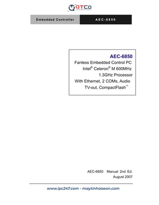
  • 1. Embedded Controller A E C - 6 8 5 0 AEC-6850 Fanless Embedded Control PC Intel® Celeron® M 600MHz 1.3GHz Processor With Ethernet, 2 COMs, Audio TV-out, CompactFlash• AEC-6850 Manual 2nd Ed. August 2007 Downloaded from www.Manualslib.com manuals search engine www.ipc247.com - maytinhaaeon.com
  • 2. Embedded Controller A E C - 6 8 5 0 i Copyright Notice This document is copyrighted, 2007. All rights are reserved. The original manufacturer reserves the right to make improvements to the products described in this manual at any time without notice. No part of this manual may be reproduced, copied, translated, or transmitted in any form or by any means without the prior written permission of the original manufacturer. Information provided in this manual is intended to be accurate and reliable. However, the original manufacturer assumes no responsibility for its use, or for any infringements upon the rights of third parties that may result from its use. The material in this document is for product information only and is subject to change without notice. While reasonable efforts have been made in the preparation of this document to assure its accuracy, AAEON assumes no liabilities resulting from errors or omissions in this document, or from the use of the information contained herein. AAEON reserves the right to make changes in the product design without notice to its users. Downloaded from www.Manualslib.com manuals search engine
  • 3. Embedded Controller A E C - 6 8 5 0 ii Acknowledgments x Award is a trademark of Award Software International, Inc. x CompactFlash™ is a trademark of the Compact Flash Association. x Intel® and Celeron® M are trademarks of Intel® Corporation. x Microsoft Windows ® is a registered trademark of Microsoft Corp. x PC/AT, PS/2, and VGA are trademarks of International Business Machines Corporation. All other product names or trademarks are properties of their respective owners. Downloaded from www.Manualslib.com manuals search engine
  • 4. Embedded Controller A E C - 6 8 5 0 iii Packing List Before you begin operating your PC, please make sure that the following materials have been shipped: z 1 AEC-6850 Embedded Control PC z 1 Keyboard mouse cable z 1 AC Power Adapter (AC version only, A1/A2 Version) z 1 Phoenix Power Connector (DC version only, A3/A4 Version) z 2 Wallmount Brackets z 1 Audio Cable z 1 Screw Package z 1 CD-ROM for manual (in PDF format) and drivers If any of these items should be missing or damaged, please contact your distributor or sales representative immediately. Downloaded from www.Manualslib.com manuals search engine
  • 5. Embedded Controller A E C - 6 8 5 0 iv Safety Warranty 1. Read these safety instructions carefully. 2. Keep this user's manual for later reference. 3. Disconnect this equipment from any AC outlet before cleaning. Do not use liquid or spray detergents for cleaning. Use a damp cloth. 4. For pluggable equipment, the power outlet must be installed near the equipment and must be easily accessible. 5. Keep this equipment away from humidity. 6. Put this equipment on a firm surface during installation. Dropping it or letting it fall could cause damage. 7. The openings on the enclosure are for air convection. Protect the equipment from overheating. DO NOT COVER THE OPENINGS. 8. Make sure the voltage of the power source is correct before connecting the equipment to the power outlet. 9. Position the power cord so that people cannot step on it. Do not place anything over the power cord. 10. All cautions and warnings on the equipment should be noted. 11. If the equipment is not used for a long time, disconnect it from the power source to avoid damage by transient over-voltage. 12. Never pour any liquid into an opening. This could cause fire or electrical shock. 13. Never open the equipment. For safety reasons, only qualified service personnel should open the equipment. 14. If any of the following situations arises, get the equipment checked by service personnel: a. The power cord or plug is damaged. b. Liquid has penetrated into the equipment. c. The equipment has been exposed to moisture. Downloaded from www.Manualslib.com manuals search engine
  • 6. Embedded Controller A E C - 6 8 5 0 v d. The equipment does not work well, or you cannot get it to work according to the user’s manual. e. The equipment has been dropped and damaged. f. The equipment has obvious signs of breakage. 15. DO NOT LEAVE THIS EQUIPMENT IN AN ENVIRONMENT WHERE THE STORAGE TEMPERATURE IS BELOW -20°C (-4°F) OR ABOVE 60°C (140°F). IT MAY DAMAGE THE EQUIPMENT. FCC Safety This device complies with Part 15 FCC Rules. Operation is subject to the following two conditions: (1) this device may not cause harmful interference, and (2) this device must accept any interference received including interference that may cause undesired operation. Caution: There is a danger of explosion if the battery is incorrectly replaced. Replace only with the same or equivalent type recommended by the manufacturer. Dispose of used batteries according to the manufacturer’s instructions and your local government’s recycling or disposal directives. Downloaded from www.Manualslib.com manuals search engine
  • 7. Embedded Controller A E C - 6 8 5 0 vi Below Table for China RoHS Requirements ѻકЁ᳝↦᳝ᆇ⠽䋼៪‫ܗ‬㋴ৡ⿄ঞ৿䞣 AAEON Boxer/ Industrial System ᳝↦᳝ᆇ⠽䋼៪‫ܗ‬㋴ 䚼ӊৡ⿄ 䪙 (Pb) ∲ (Hg) 䬝 (Cd) ݁Ӌ䫀 (Cr(VI)) ໮⒈㘨㣃 (PBB) ໮⒈Ѡ㣃 䝮(PBDE) ॄࠋ⬉䏃ᵓ ঞ݊⬉ᄤ㒘ӊ h ƻ ƻ ƻ ƻ ƻ ໪䚼ֵো 䖲᥹఼ঞ㒓ᴤ h ƻ ƻ ƻ ƻ ƻ ໪໇ h ƻ ƻ ƻ ƻ ƻ Ё༂໘⧚఼ Ϣ‫ݙ‬ᄬ h ƻ ƻ ƻ ƻ ƻ ⹀Ⲭ h ƻ ƻ ƻ ƻ ƻ ⬉⑤ h ƻ ƻ ƻ ƻ ƻ O˖㸼⼎䆹᳝↦᳝ᆇ⠽䋼೼䆹䚼ӊ᠔᳝ഛ䋼ᴤ᭭Ёⱘ৿䞣ഛ೼ SJ/T 11363-2006 ᷛ‫ޚ‬㾘ᅮⱘ䰤䞣㽕∖ҹϟDŽ X˖㸼⼎䆹᳝↦᳝ᆇ⠽䋼㟇ᇥ೼䆹䚼ӊⱘᶤϔഛ䋼ᴤ᭭Ёⱘ৿䞣䍙ߎ SJ/T 11363-2006 ᷛ‫ޚ‬㾘ᅮⱘ䰤䞣㽕∖DŽ ໛⊼˖ ϔǃℸѻક᠔ᷛ⼎П⦃ֱՓ⫼ᳳ䰤ˈ㋏ᣛ೼ϔ㠀ℷᐌՓ⫼⢊‫މ‬ϟDŽ ѠǃϞ䗄䚼ӊ⠽䋼Ё༂໘⧚఼ǃ‫ݙ‬ᄬǃ⹀Ⲭǃ⬉⑤Ў䗝䌁કDŽ Downloaded from www.Manualslib.com manuals search engine
  • 8. Embedded Controller A E C - 6 8 5 0 vii Contents Chapter 1 General Information 1.1 Introduction................................................................ 1-2 1.2 Features .................................................................... 1-4 1.3 Specifications ............................................................ 1-5 Chapter 2 Hardware Installation 2.1 Dimension ................................................................. 2-2 2.2 SDRAM Installation ................................................... 2-3 2.3 Internal CF Card Installation (IDE interface CF slot for boot up) ........................................................................... 2-4 2.4 COM2 RS-232/422/485 Setting ................................ 2-6 2.5 COM2 RS-232/422/485 Serial Port Connector......... 2-6 2.6 COM 1 RS-232 Serial Port Connector ...................... 2-6 2.7 CD-ROM and 2.5” HDD Kit Installation..................... 2-7 2.8 Dual 2.5” HDD Kit Installation ................................... 2-11 2.9 3.5” HDD Kit Installation............................................ 2-15 2.10 Wallmount Bracket Installation................................ 2-19 Chapter 3 Award BIOS Setup 3.1 System Test and Initialization. .................................. 3-2 3.2 Award BIOS Setup .................................................... 3-3 Chapter 4 Driver Installation 4.1 Installation ................................................................. 4-3 Downloaded from www.Manualslib.com manuals search engine
  • 9. Embedded Controller A E C - 6 8 5 0 viii Appendix A Programming The Watchdog Timer A.1 Programming ........................................................A-2 A.2 ITE8712 Watchdog Timer Initial Program ............A-6 Appendix B I/O Information B.1 I/O Address Map ..................................................B-2 B.2 1st MB Memory Address Map ...............................B-2 B.3 IRQ Mapping Chart ..............................................B-3 B.2 DMA Channel Assignments .................................B-3 Downloaded from www.Manualslib.com manuals search engine
  • 10. Embedded Controller A E C - 6 8 5 0 Chapter 1 General Information 1- 1 General Chapter 1 Information Downloaded from www.Manualslib.com manuals search engine
  • 11. Embedded Controller A E C - 6 8 5 0 Chapter 1 General Information 1-2 1.1 Introduction Due to the growing popularity from the IPC market, the newest Boxer series AEC-6850 has been introduced by AAEON. Compared with the AEC-6830, it is an advanced version because it utilizes an Intel® Celeron® processor without a fan. New Innovation for Entertainment Multimedia Domain In this era of information explosion, the advertising of consumer products will not be confined to the family television, but will also spread to high-traffic public areas, like department stores, the bus, transportation station, the supermarket etc. The advertising marketing industry will resort to every conceivable means to transmit product information to consumers. System integrators will need a multifunction device to satisfy commercial needs for such public advertising. Being a control center, the AEC-6850 is suitable for public multimedia entertainment services. Equipped with a high efficiency heat conduction mechanism, which is patented in Germany, the AEC-6850 supports up to Celeron ® M 1.3GHz processor. The AEC-6850 is compact in size but has attractive and flexible extension capabilities such as a 4-in-one card reader, 3 USB2.0 ports, VGA, TV-out, DVI, Audio, 2 COM ports and an optional IEEE 1394(FireWire) port. Downloaded from www.Manualslib.com manuals search engine
  • 12. Embedded Controller A E C - 6 8 5 0 Chapter 1 General Information 1- 3 Stable Design for Rugged Environment The AEC-6850 is designed for rugged environments due to the following reasons; first, it can withstand tough vibration testing up to 5G rms. With the anti-vibration hard drive device option, the AEC-6850 can be used in high vibration environments. In addition, the AEC-6850 offers low power consumption system that while operating in ambient temperatures ranging from -15° to 60°C. The MTBF(Mean Time Before Failure) rating states that the AEC-6850 can operate up to 50,000 hours at 35°C ambient temperature, which indicates its careful and long-life design. The AEC-6850 is a standalone high performance controller designed for long-life operation and with high reliability. It can replace traditional methods and become the mainstream controller for the multimedia entertainment market. Downloaded from www.Manualslib.com manuals search engine
  • 13. Embedded Controller A E C - 6 8 5 0 Chapter 1 General Information 1-4 1.2 Features x Fanless Design with Intel® Celeron® M 600MHz / 1.3GHz Processor x 4 in 1 Card Reader x 2 COM / S-video / 3 USB 2.0 / Ethernet Downloaded from www.Manualslib.com manuals search engine
  • 14. Embedded Controller A E C - 6 8 5 0 Chapter 1 General Information 1- 5 1.3 Specifications System z CPU: Intel® Celeron® M 600MHz/ 1.3GHz Processor z Construction: Rugged Aluminum Alloy chassis z System Memory: DDR SODIMM x 1, Max. 512MB z VGA: DB-15 VGA connector z Keyboard/Mouse: PS/2 Keyboard Mouse z Ethernet: 10/100Base-TX RJ-45 connector x 1 z SSD: Internal Type II CompactFlash™ slot x 1 z Card Reader: CompactFlash™ , SD/ MMC/ MS/ XD z Device Bay (Optional): CD-ROM 2.5”HDD Kit, 2 x 2.5” HDD Kit, 3.5” HDD Kit z Serial Port: 1 x RS-232, 1 x RS-232/422/485 z Audio: MIC / Line In / Line Out by expansion cable z USB: 3 USB 2.0 ports z DVI: DVI connector x 1 z Watchdog Timer: Generate a time-out System reset, setting via software z Power Supply: A1/A2 Version—AC Input: External Power Adapter; Input Voltage: 100V AC~240V AC@ 50 ~ 60Hz; A3/A4 Version—DC Input: 9V DC~30V DC Downloaded from www.Manualslib.com manuals search engine
  • 15. Embedded Controller A E C - 6 8 5 0 Chapter 1 General Information 1-6 z System Control: Power on / off switch x 1; Reset button x 1 z Indicator: Power LED x 1; HDD active LED x 1 z OS Support: Windows® CE. NET, Windows® XP Embedded, Windows® XP, Windows® 2000 Mechanical and Environmental z Construction: Rugged Aluminum Alloy chassis z Color: Dark Blue z Mounting: Wallmount, Desktop z Dimension: 8.35” (W) x 2.53” (H) x 6.26” (D) (212mm x 64mm x 159mm) z Net Weight: 5.57lb (2.53kg) z Gross Weight: 10.34lb (4.7kg) z Operation Temperature: 14°F~140°F (-15°C~60°C) – Celeron® M 600MHz/CFD; 14°F~122°F(-15°C~50°C) –Celeron® M 600MHz/HDD; 14°F ~ 122°F (-15°C ~ 50°C) – Celeron® M 1.3GHz/CFD; 14°F ~ 113°F (-15°C ~ 45°C) – Celeron® M 1.3GHz/HDD z Operation Humidity: 5~95% @ 40°C, non-condensing Downloaded from www.Manualslib.com manuals search engine
  • 16. Embedded Controller A E C - 6 8 5 0 Chapter 1 General Information 1- 7 z Vibration: 5 g rms / 5~500Hz / random operation (CFD) 1 g / 5~500Hz / random operation (HDD) z Shock: 100g peak acceleration (11 msec. duration) 15g peak acceleration (11 msec. duration) (HDD) z EMC: CE/FCC class B Downloaded from www.Manualslib.com manuals search engine
  • 17. Embedded Controller A E C - 6 8 5 0 Chapter 1 General Information 1-8 Front Side Rear Side TV-Out S-Video Ethernet RJ-45, 10/100 Audio Mini-Din 9-pin Line Out/In, MIC In Line out USB 2.0 Port x 2 HDD LED Reset Power Switch 4-in-1 Card Reader DVI KB/Mouse Mini-DIN 6-pin VGA D-sub 15-pin Serial port D-sub 9-pin Serial port D-sub 9-pin USB 2.0 Port x 1 Power LED Power Inlet Mini-Din 4-pin Downloaded from www.Manualslib.com manuals search engine
  • 18. Embedded Controller A E C - 6 8 5 0 Chapter 2 Hardware Installation 2-1 Hardware Installation Chapter 2 Downloaded from www.Manualslib.com manuals search engine
  • 19. Embedded Controller A E C - 6 8 5 0 Chapter 2 Hardware Installation 2 - 2 2.1 Dimension Downloaded from www.Manualslib.com manuals search engine
  • 20. Embedded Controller A E C - 6 8 5 0 Chapter 2 Hardware Installation 2 - 3 2.2 SDRAM Installation Step 1: Take off the lid from the bottom of the chassis by loosening the screws. Step 2: Insert the SDRAM Module into the slot. X SDRAM Module Slot Y Downloaded from www.Manualslib.com manuals search engine
  • 21. Embedded Controller A E C - 6 8 5 0 Chapter 2 Hardware Installation 2 - 4 Step 3: Place the lid back on and lock with screws. 2.3 Internal CF Card Installation (IDE interface CF slot for boot up) Step 1: Take off the lid from the bottom of the chassis by loosening the screws. Downloaded from www.Manualslib.com manuals search engine
  • 22. Embedded Controller A E C - 6 8 5 0 Chapter 2 Hardware Installation 2 - 5 Step 2: Insert the CF Card into the slot. X CF Card Slot Push Y Step 3: Place the lid back on and lock with screws. Downloaded from www.Manualslib.com manuals search engine
  • 23. Embedded Controller A E C - 6 8 5 0 Chapter 2 Hardware Installation 2 - 6 2.4 COM2 RS-232/422/485 Setting Note: RS-232/422/485 Selection by BIOS 2.5 COM2 RS-232/422/485 Serial Port Connector Different devices implement the RS-232/422/485 standard in different ways. If you are having problems with a serial device, be sure to check the pin assignments below for the connector. Pin Signal Pin Signal 1 DCD (422TXD-/485DATA-) 2 RXD (422RXD+) 3 TXD (422TXD+/485DATA+) 4 DTR (422RXD-) 5 GND 6 DSR 7 RTS 8 CTS 9 RI 10 N.C. 2.6 COM1 RS-232 Serial Port Connector Pin Signal Pin Signal 1 DCD 2 RXD 3 TXD 4 DTR 5 GND 6 DSR 7 RTS 8 CTS 9 RI 10 N.C. Downloaded from www.Manualslib.com manuals search engine
  • 24. Embedded Controller A E C - 6 8 5 0 Chapter 2 Hardware Installation 2 - 7 2.7 CD-ROM and 2.5” HDD Kit Installation CD-ROM and 2.5” HDD Kit Combination Step 1: Get the disk bracket ready. Step 2: Fasten the CD-ROM to the disk bracket with screws. Downloaded from www.Manualslib.com manuals search engine
  • 25. Embedded Controller A E C - 6 8 5 0 Chapter 2 Hardware Installation 2 - 8 Step 3: Fasten the Riser Card and the CD-ROM with screws. Step 4: Fasten the 2.5” HDD module to the disk bracket with screws. Riser Card Step 5: Insert the flat cable into the slots on the Riser Card and the 2.5” HDD module. Flat Cable Downloaded from www.Manualslib.com manuals search engine
  • 26. Embedded Controller A E C - 6 8 5 0 Chapter 2 Hardware Installation 2 - 9 Step 6: Place the CD-ROM and HDD kit into the suitable plate and then reverse it. Screw the CD-ROM and HDD kit to the plate. Cable Insertion Step 1: Open the HDD cover by loosening the screws on the bottom of the chassis. Downloaded from www.Manualslib.com manuals search engine
  • 27. Embedded Controller A E C - 6 8 5 0 Chapter 2 Hardware Installation 2 - 10 Step 2: Insert the other side of flat cable into the slot on the bottom of the chassis. Flat Cable Step 3: Combine the chassis with the CD-ROM and 2.5” HDD kit plate. Then lock with screws. Downloaded from www.Manualslib.com manuals search engine
  • 28. Embedded Controller A E C - 6 8 5 0 Chapter 2 Hardware Installation 2 - 11 2.8 Dual 2.5” HDD Kit Installation HDD Kit Combination Step 1: Get the bracket ready. Attach the rubber shock absorbers with the bracket as illustration shown below. Step 2: Fasten the first HDD module to the bracket with screws. Step 3: Fasten the second HDD module to the bracket with screws. Downloaded from www.Manualslib.com manuals search engine
  • 29. Embedded Controller A E C - 6 8 5 0 Chapter 2 Hardware Installation 2 - 12 Step 4: Insert the HDD cable into the slot on the HDD module. HDD Cable Step 5: Place the HDD kit into the HDD kit housing and then screw the HDD kit onto the HDD kit housing. Downloaded from www.Manualslib.com manuals search engine
  • 30. Embedded Controller A E C - 6 8 5 0 Chapter 2 Hardware Installation 2 - 13 Cable Insertion Step 1: Open the HDD cover by loosening the screws on the bottom of the chassis. Step 2: Insert the other side of HDD cable into the slot on the bottom of the chassis. HDD Cable Downloaded from www.Manualslib.com manuals search engine
  • 31. Embedded Controller A E C - 6 8 5 0 Chapter 2 Hardware Installation 2 - 14 Step 3: Combine the chassis with the HDD kit housing and then lock with screws. Downloaded from www.Manualslib.com manuals search engine
  • 32. Embedded Controller A E C - 6 8 5 0 Chapter 2 Hardware Installation 2 - 15 2.9 3.5” HDD Kit Installation HDD Kit Combination Step 1: Get the HDD module ready. Insert power cable and HDD cable into the slots on the HDD module. Power Cable HDD Cable Step 2: Get the bracket ready. Downloaded from www.Manualslib.com manuals search engine
  • 33. Embedded Controller A E C - 6 8 5 0 Chapter 2 Hardware Installation 2 - 16 Step 3: Attach the rubber shock absorbers to the bracket as illustration shown below. Step 4: Fasten the HDD module to the bracket with screws. Downloaded from www.Manualslib.com manuals search engine
  • 34. Embedded Controller A E C - 6 8 5 0 Chapter 2 Hardware Installation 2 - 17 Step 5: Get the screws ready, by matching them up with a washer. Meanwhile, place the HDD kit into the HDD kit housing and then screw the HDD kit to the HDD kit housing. Magnificent Cable Insertion Step 1: Open the HDD cover by loosening the screws on the bottom of the chassis. Downloaded from www.Manualslib.com manuals search engine
  • 35. Embedded Controller A E C - 6 8 5 0 Chapter 2 Hardware Installation 2 - 18 Step 2: Insert the other side of HDD cable and power cable into the slots on the bottom of the chassis. HDD Cable Power Cable Step 3: Combine the chassis with the HDD kit housing and then lock with screws. Downloaded from www.Manualslib.com manuals search engine
  • 36. Embedded Controller A E C - 6 8 5 0 Chapter 2 Hardware Installation 2 - 19 2.10 Wallmount Bracket Installation Fasten the brackets with the appropriate screws. Bracket Bracket Downloaded from www.Manualslib.com manuals search engine
  • 37. Embedded Controller A E C - 6 8 5 0 Chapter 3 Award BIOS Setup 3-1 Chapter Award 3 BIOS Setup Downloaded from www.Manualslib.com manuals search engine
  • 38. Embedded Controller A E C - 6 8 5 0 Chapter 3 Award BIOS Setup 3-2 3.1 System Test and Initialization These routines test and initialize board hardware. If the routines encounter an error during the tests, you will either hear a few short beeps or see an error message on the screen. There are two kinds of errors: fatal and non-fatal. The system can usually continue the boot up sequence with non-fatal errors. Non-fatal error messages usually appear on the screen along with the following instructions: Press F1 to RESUME Write down the message and press the F1 key to continue the boot up sequence. System configuration verification These routines check the current system configuration against the values stored in the CMOS memory. If they do not match, the program outputs an error message. You will then need to run the BIOS setup program to set the configuration information in memory. There are three situations in which you will need to change the CMOS settings: 1. You are starting your system for the first time 2. You have changed the hardware attached to your system 3. The CMOS memory has lost power and the configuration information has been erased. The AEC-6850 CMOS memory has an integral lithium battery backup for data retention. However, you will need to replace the complete unit when it finally runs down. Downloaded from www.Manualslib.com manuals search engine
  • 39. Embedded Controller A E C - 6 8 5 0 Chapter 3 Award BIOS Setup 3-3 3.2 Award BIOS Setup Awards BIOS ROM has a built-in Setup program that allows users to modify the basic system configuration. This type of information is stored in battery-backed CMOS RAM so that it retains the Setup information when the power is turned off. Entering Setup Power on the computer and press Del immediately. This will allow you to enter Setup. Standard CMOS Features Use this menu for basic system configuration. (Date, time, IDE, etc.) Advanced BIOS Features Use this menu to set the advanced features available on your system. Advanced Chipset Features Use this menu to change the values in the chipset registers and optimize your system performance. Downloaded from www.Manualslib.com manuals search engine
  • 40. Embedded Controller A E C - 6 8 5 0 Chapter 3 Award BIOS Setup 3-4 Integrated Peripherals Use this menu to specify your settings for integrated peripherals. (Primary slave, secondary slave, keyboard, mouse etc.) Power Management Setup Use this menu to specify your settings for power management. (HDD power down, power on by ring, KB wake up, etc.) PnP/PCI Configurations This entry appears if your system supports PnP/PCI. PC Health Status This menu allows you to set the shutdown temperature for your system. Frequency/Voltage Control Use this menu to specify your settings for auto detect DIMM/PCI clock and spread spectrum. Load Fail-Safe Defaults Use this menu to load the BIOS default values for the minimal/stable performance for your system to operate. Load Optimized Defaults Use this menu to load the BIOS default values that are factory settings for optimal performance system operations. While AWARD has designated the custom BIOS to maximize performance, the factory has the right to change these defaults to meet their needs. Set Supervisor/User Password Use this menu to set Supervisor/User Passwords. Downloaded from www.Manualslib.com manuals search engine
  • 41. Embedded Controller A E C - 6 8 5 0 Chapter 3 Award BIOS Setup 3-5 Save and Exit Setup Save CMOS value changes to CMOS and exit setup. Exit Without Saving Abandon all CMOS value changes and exit setup. You can refer to the AAEON BIOS Item Description.pdf file in the CD for the meaning of each setting in this chapter. Downloaded from www.Manualslib.com manuals search engine
  • 42. Embedded Controller A E C - 6 8 5 0 Chapter 4 Driver Installation 4 - 1 Chapter Driv 4er Installation Downloaded from www.Manualslib.com manuals search engine
  • 43. Embedded Controller A E C - 6 8 5 0 Chapter 4 Driver Installation 4 - 2 The AEC-6850 comes with a CD-ROM that contains all drivers and utilities that meet your needs. Follow the sequence below to install the drivers: Step 1 – Install Intel INF Update for Windows 9x-2003 Step 2 – Install Intel Extreme Graphics 2 Driver Step 3 – Install Intel LAN Driver Step 4 – Install Realtek AC97 codec Driver Step 5 – Install USB Card Reader Driver USB 2.0 Drivers are available for download using Windows Update for both Windows XP and Windows 2000. For additional information regarding USB 2.0 support in Windows XP and Windows 2000, please visit www.microsoft.com/hwdev/usb/. Please read instructions below for further detailed installations. Downloaded from www.Manualslib.com manuals search engine
  • 44. Embedded Controller A E C - 6 8 5 0 Chapter 4 Drivers Installation 4 - 3 4.1 Installation Insert the AEC-6850 CD-ROM into the CD-ROM Drive. And install the drivers from Step 1 to Step 5 in order. Step 1 – Install Intel INF Update for Windows 9x-2003 1. Click on the Step 1 - Intel INF Update for Windows 9x-2003 folder and then double click on the setup.exe. 2. Follow the instructions that the window shows you 3. The system will help you install the driver automatically Step 2 – Install Intel Extreme Graphics 2 Driver 1. Click on the Step 2 - Intel Extreme Graphics 2 Driver folder and select the OS your system is 2. Double click on the setup.exe 3. Follow the instructions that the window shows you 4. The system will help you install the driver automatically 5. Please re-start your computer Remark: You can choose the different display ways by pressing below hot key, Ctrl+Alt+F1=CRT, Ctrl+Alt+F2=LCD, Ctrl+Alt+F3=TV, Ctrl+Alt+F4=DVI, Ctrl+Alt+F12=Graphic Control Panel Step 3 – Install Intel LAN Driver 1. Click on the Step 3 - Intel LAN Driver folder and select the OS your system is 2. Double click on the .exe file Downloaded from www.Manualslib.com manuals search engine
  • 45. Embedded Controller A E C - 6 8 5 0 Chapter 4 Driver Installation 4 - 4 3. Follow the instructions that the window shows you 4. The system will help you install the driver automatically Step 4 – Install Realtek AC97 codec Driver 1. Click on the Step 4 - Realtek AC97 codec Driver folder and then double click on the wdm_a361.exe 2. Follow the instructions that the window shows you 3. The system will help you install the driver automatically Step 5 – Install USB Card Reader Driver 1. Click on the Step 5 – USB Card Reader Driver folder 2. Double click on the setup.exe 3. Language setting: Choose the highlighted item below to operate your system in English. 4. Follow the instruction that the window will show to finish the installation. Note: Under the Window OS environment, if the CRT connector is connected to display monitor by the data switch device, the user need to set the color and resolution from Intel Graphic utility (VGA driver) instead of setting from the control panel in case of the wrong display appearance. Downloaded from www.Manualslib.com manuals search engine
  • 46. Embedded Controller A E C - 6 8 5 0 Appendix A Programming the Watchdog Timer A-1 Programming the Appendix A Watchdog Timer Downloaded from www.Manualslib.com manuals search engine
  • 47. Embedded Controller A E C - 6 8 5 0 Appendix A Programming the Watchdog Timer A-2 A.1 Programming AEC-6850 utilizes ITE 8712 chipset as its watchdog timer controller. Below are the procedures to complete its configuration and the AAEON intial watchdog timer program is also attached based on which you can develop customized program to fit your application. Configuring Sequence Description After the hardware reset or power-on reset, the ITE 8712 enters the normal mode with all logical devices disabled except KBC. The initial state (enable bit ) of this logical device (KBC) is determined by the state of pin 121 (DTR1#) at the falling edge of the system reset during power-on reset. Downloaded from www.Manualslib.com manuals search engine
  • 48. Embedded Controller A E C - 6 8 5 0 Appendix A Programming the Watchdog Timer A-3 There are three steps to complete the configuration setup: (1) Enter the MB PnP Mode; (2) Modify the data of configuration registers; (3) Exit the MB PnP Mode. Undesired result may occur if the MB PnP Mode is not exited normally. (1) Enter the MB PnP Mode To enter the MB PnP Mode, four special I/O write operations are to be performed during Wait for Key state. To ensure the initial state of the key-check logic, it is necessary to perform four write opera-tions to the Special Address port (2EH). Two different enter keys are provided to select configuration ports (2Eh/2Fh) of the next step. (2) Modify the Data of the Registers All configuration registers can be accessed after entering the MB PnP Mode. Before accessing a selected register, the content of Index 07h must be changed to the LDN to which the register belongs, except some Global registers. (3) Exit the MB PnP Mode Set bit 1 of the configure control register (Index=02h) to 1 to exit the MB PnP Mode. Downloaded from www.Manualslib.com manuals search engine
  • 49. Embedded Controller A E C - 6 8 5 0 Appendix A Programming the Watchdog Timer A-4 WatchDog Timer Configuration Registers Configure Control (Index=02h) This register is write only. Its values are not sticky; that is to say, a hardware reset will automatically clear the bits, and does not require the software to clear them. Downloaded from www.Manualslib.com manuals search engine
  • 50. Embedded Controller A E C - 6 8 5 0 Appendix A Programming the Watchdog Timer A-5 WatchDog Timer Control Register (Index=71h, Default=00h) WatchDog Timer Configuration Register (Index=72h, Default=00h WatchDog Timer Time-out Value Register (Index=73h, Default=00h) Downloaded from www.Manualslib.com manuals search engine
  • 51. Embedded Controller A E C - 6 8 5 0 Appendix A Programming the Watchdog Timer A-6 A.2 ITE8712 Watchdog Timer Initial Program .MODEL SMALL .CODE Main: CALL Enter_Configuration_mode CALL Check_Chip mov cl, 7 call Set_Logic_Device ;time setting mov cl, 10 ; 10 Sec dec al Watch_Dog_Setting: ;Timer setting mov al, cl mov cl, 73h call Superio_Set_Reg ;Clear by keyboard or mouse interrupt mov al, 0f0h mov cl, 71h call Superio_Set_Reg ;unit is second. mov al, 0C0H mov cl, 72h call Superio_Set_Reg Downloaded from www.Manualslib.com manuals search engine
  • 52. Embedded Controller A E C - 6 8 5 0 Appendix A Programming the Watchdog Timer A-7 ; game port enable mov cl, 9 call Set_Logic_Device Initial_OK: CALL Exit_Configuration_mode MOV AH,4Ch INT 21h Enter_Configuration_Mode PROC NEAR MOV SI,WORD PTR CS:[Offset Cfg_Port] MOV DX,02Eh MOV CX,04h Init_1: MOV AL,BYTE PTR CS:[SI] OUT DX,AL INC SI LOOP Init_1 RET Enter_Configuration_Mode ENDP Exit_Configuration_Mode PROC NEAR MOV AX,0202h CALL Write_Configuration_Data Downloaded from www.Manualslib.com manuals search engine
  • 53. Embedded Controller A E C - 6 8 5 0 Appendix A Programming the Watchdog Timer A-8 RET Exit_Configuration_Mode ENDP Check_Chip PROC NEAR MOV AL,20h CALL Read_Configuration_Data CMP AL,87h JNE Not_Initial MOV AL,21h CALL Read_Configuration_Data CMP AL,12h JNE Not_Initial Need_Initial: STC RET Not_Initial: CLC RET Check_Chip ENDP Read_Configuration_Data PROC NEAR MOV DX,WORD PTR CS:[Cfg_Port+04h] OUT DX,AL Downloaded from www.Manualslib.com manuals search engine
  • 54. Embedded Controller A E C - 6 8 5 0 Appendix A Programming the Watchdog Timer A-9 MOV DX,WORD PTR CS:[Cfg_Port+06h] IN AL,DX RET Read_Configuration_Data ENDP Write_Configuration_Data PROC NEAR MOV DX,WORD PTR CS:[Cfg_Port+04h] OUT DX,AL XCHG AL,AH MOV DX,WORD PTR CS:[Cfg_Port+06h] OUT DX,AL RET Write_Configuration_Data ENDP Superio_Set_Reg proc near push ax MOV DX,WORD PTR CS:[Cfg_Port+04h] mov al,cl out dx,al pop ax inc dx out dx,al ret Superio_Set_Reg endp.Set_Logic_Device proc near Set_Logic_Device proc near Downloaded from www.Manualslib.com manuals search engine
  • 55. Embedded Controller A E C - 6 8 5 0 Appendix A Programming the Watchdog Timer A-10 push ax push cx xchg al,cl mov cl,07h call Superio_Set_Reg pop cx pop ax ret Set_Logic_Device endp ;Select 02Eh-Index Port, 02Fh-Data Port Cfg_Port DB 087h,001h,055h,055h DW 02Eh,02Fh END Main Note: Interrupt level mapping 0Fh-Dh: not valid 0Ch: IRQ12 . . 03h: IRQ3 02h: not valid 01h: IRQ1 00h: no interrupt selected Downloaded from www.Manualslib.com manuals search engine
  • 56. Embedded Controller A E C - 6 8 5 0 Appendix B I/O Information B-1 I/O Information Appendix B Downloaded from www.Manualslib.com manuals search engine
  • 57. Embedded Controller A E C - 6 8 5 0 Appendix B I/O Information B-2 B.1 I/O Address Map Address Description User Address 000-01F DMA Controller #1 000-000F 020-03F Interrupt Controller #1, Master 020-021 040-05F System Time 040-043 060-06F 8042 (Keyboard Controller) 060-064 070-07F Real time Clock, NMI (non-maskable Interrupt) Mask 070-073 080-09F DMA Page Register 080-08F 0A0-0BF Interrupt Controller #2 0A0-0A1 0C0-0DF DMA Controller #2 0C0-0DF 0F0-0FF Math Coprpcessor 0F0-0FF 170-177 Secondary IDE Channel 170-177 1F0-1F7 Primary IDE Channel 1F0-1F7 2F8-2FF Serial Port 2 2F8-2FF 378-37F Parallel Printer Port 1 378-37F 3B0-3DF EGA / VGA card 3B0-3DF 3F8-3FF Serial Port 1 3F8-3FF B.2 1st MB Memory Address Map Memory Address Description 00000-9FFFF System memory A0000-BFFFF VGA buffer C0000-CFFFF VGA BIOS E0000-FFFFF System BIOS Downloaded from www.Manualslib.com manuals search engine
  • 58. Embedded Controller A E C - 6 8 5 0 Appendix B I/O Information B-3 B.3 IRQ Mapping Chart IRQ0 System Timer IRQ8 System CMOS / Real time clock IRQ1 Keyboard IRQ9 Microsoft ACPI – Compliant system IRQ2 Cascade to IRQ Controller IRQ10 Unused IRQ3 COM2 IRQ11 Unused IRQ4 COM1 IRQ12 PS/2 mouse IRQ5 Unused IRQ13 FPU IRQ6 Unused IRQ14 Primary IDE IRQ7 Printer IRQ15 Secondary IDE B.4 DMA Channel Assignments DMA Channel Function 0 Available 1 Available 2 Unused 3 Available 4 Direct Memory Access Controller 5 Available 6 Available 7 Available Downloaded from www.Manualslib.com manuals search engine