1. HTE302172 0/38
6
6
6
6
Ins
Ins
Ins
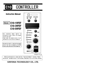
Instruction Manual
truction Manual
truction Manual
truction Manual
Model
This instruction ma
This instruction ma
This instruction ma
This instruction manual applies to
nual applies to
nual applies to
nual applies to
C10
C10
C10
C10-
-
-
-controller
controller
controller
controller whic
whic
whic
which installs the
h installs the
h installs the
h installs the program
program
program
program
version 6
version 6
version 6
version 6 and later.
and later.
and later.
and later.
Please check the program version of your
Please check the program version of your
Please check the program version of your
Please check the program version of your
C10
C10
C10
C10-
-
-
-controller
controller
controller
controller on the version information.
on the version information.
on the version information.
on the version information.
The controller which is installed the program
The controller which is installed the program
The controller which is installed the program
The controller which is installed the program
version
version
version
version 5
5
5
5 and later co
and later co
and later co
and later corresponds
rresponds
rresponds
rresponds to
to
to
to the
the
the
the RoHS
RoHS
RoHS
RoHS
Directive
Directive
Directive
Directive and confirms with the CE Marking
and confirms with the CE Marking
and confirms with the CE Marking
and confirms with the CE Marking.
.
.
.
B
B
B
Before use
efore use
efore use
efore use C10
C10
C10
C10-
-
-
-controller
controller
controller
controller, please read this
, please read this
, please read this
, please read this “
“
“
“Instruction Manual
Instruction Manual
Instruction Manual
Instruction Manual”
”
”
” including
including
including
including “
“
“
“Safety
Safety
Safety
Safety
Instructions
Instructions
Instructions
Instructions”
”
”
” thoroughly to use it in the right way. Please keep it on file for further reference.
thoroughly to use it in the right way. Please keep it on file for further reference.
thoroughly to use it in the right way. Please keep it on file for further reference.
thoroughly to use it in the right way. Please keep it on file for further reference.
CONTROLLER
CONTROLLER
CONTROLLER
CONTROLLER
5
HTE302172 0/46
6
2. 5
HTE302172 1/46
6
Thank you for buying your C10-Series controller. Before use C10-controller,
please read this “Instruction Manual”, including “Safety Instructions”, thoroughly to use
C10-controller safely and in the right way. Please keep it on file for further reference and/or
maintenance. Please hand this manual to the operator of the partsfeeder.
Introduction…………………………………………………………………… 1
Safety Instructions ………………………………………………………… 2
Wiring Connections ………………………………………………………… 5
How to operate the Control Panel ……………………………………… 7
・ Name and Function of the Buttons, Lamps and Dials on the Control Panel …… 7
・ How to Run and Stop the Partsfeeder …… 8
・ Alarm by blinking “RUN” lamp …… 8
・ Basic Setting up Procedure …… 9
・ How to adjust the Function Set Value …… 11
Initial Setting ……………………………………………………………… 13
・ Preparation for operation …… 13
・ How to adjust the Drive Frequency Output Range …… 14
・ How to adjust the Stroke on the Auto-tuning Mode …… 16
・ How to set the Stroke on the Constant Voltage Mode …… 18
・ How to adjust the Stroke on the Constant Stroke Mode …… 20
・ Scaling of the stroke …… 22
Additional Function…………………………………………………………………24
・Setting up for Key Lock function …… 24
・Setting On and Off Delay Time …… 24
・Setting of Soft Start Ramp-up Time …… 24
・Connection of Overflow and Stroke sensors …… 25
How to use External Signal Terminals ………………………………………… 29
・External Operation Signal Terminals “P1” and “P2” …… 29
・Operation Synchronous Signal Terminals “Q1” and “Q2”.and “AUX .OUT”…… 30
・Speed Change /Control by 4-20mA Current
/Two-Rate-of-Feed control by External Rheostats …… 30
Conformity with CE Marking ………………………………………………… 36
Trouble shooting …………………………………………………………………… 39
Function Table ……………………………………………………………………… 40
How to Initialize the Settings ………………………………………………… 41
Outline Dimensions…………………………………………………………………… 42
Accessory List ……………………………………………………………………… 43
Specifications ……………………………………………………………………… 44
Guarantee …………………………………………………………………………… 45
Introduction
Introduction
Introduction
Introduction
Sales offices …………………………………………………………………………… 46
Contents
Contents
Contents
Contents
5
HTE302172 2/46
6
Before use C10-controller, please read this “Safety Instructions” carefully to use C10-controller in
the right way.
Use of this C10-controller involves electrical current. There is potential hazard of electric shock to
the operator. Failure to follow these instructions may result serious personal injury or property damage.
Safety Instructions are classified into
Safety Instructions are classified into
Safety Instructions are classified into
Safety Instructions are classified into “
“
“
“Danger
Danger
Danger
Danger”
”
”
”,
,
,
, “
“
“
“Warning
Warning
Warning
Warning”
”
”
”,
,
,
, “
“
“
“Caution
Caution
Caution
Caution”
”
”
” and
and
and
and “
“
“
“Request
Request
Request
Request”
”
”
”.
.
.
.
This label shows an immediate danger.
Misuse of C10-controller and/or risky action of any person should cause the
person serious and/or fatal injury and/or severe damage to your property.
This label shows an indirect danger.
Misuse of the partsfeeder and/or risky action of any person should cause
the person injury and/or damage to your property.
This label shows an indirect danger.
Misuse of C10-controller and/or risky action of any person might cause the
person injury and/or damage to your property.
This label shows the manufacturer’s strong recommendation to use the
partsfeeder properly.
Misuse of C10-controller and/or risky action of any person may not cause
the person injury and/or damage of your property.
■Please keep this “Instruction Manual” on file for further reference giving easy access
to the operator.
■The partsfeeder that is sold or rented to the other must keep this “Instruction Manual”
on it highly visible.
They must use the partsfeeder in the right way.
■Not all danger should be covered by the “Instruction Manual”. Please read the Instruction
Manual and act on the principle of Safety First.
Safety Instructions
Safety Instructions
Safety Instructions
Safety Instructions
- Please read this article thoroughly without fail -
Danger
Danger
Danger
Danger
Warning
Warning
Warning
Warning
Caution
Caution
Caution
Caution
Request
Request
Request
Request
3. 5
HTE302172 3/46
6
Don’t apply C10-controller to a piezo-electric type partsfeeder.
Don’t use C10-controller where inflammable material exists. It has not an
explosion-proof structure.
You should fix the controller firmly on the rigid structure. Otherwise the operator
might be injured by falling down and/or abnormal operation of it.
Don’t sprinkle C10-controller with water and/or submerge it in water, or cause the
operator injury and/or get an electric shock.
Before performing any maintenance work, such as opening cover, wiring, replacing fuse
and etc., the electrical supply must be disconnected at the safety disconnect switch.
The electrical circuit inside involves high voltage and the operator should get an
electric shock.
The electrical power supply to C10-controller must be made through a customer-supplied
safety disconnect switch mounted next to C10-controller.
Operate C10-controller within the specified range in the contracted specifications,
or it causes it malfunction, damage and/or shorter life time.
Don’t get on and/or put a thing on the controller, or it results injury by fall, and/or
damage and/or malfunction of it.
Don’t bruise cords and/or leads. Bending by force, pulling, winding and/or clamping
them cause fire and/or getting an electric shock by leakage and/or mal-conduction,
and/or abnormal operation.
Wire C10-controller correctly consulting the “Instruction Manual”. Faulty wiring
causes damage and/or abnormal operation of it.
Before supply C10-controller electrical power, check the wiring.
C10-controller must be grounded properly without fail. Don’t operate it without
grounding.
Warning
Warning
Warning
Warning
Danger
Danger
Danger
Danger
Safety Instructions
Safety Instructions
Safety Instructions
Safety Instructions
-Continued-
5
HTE302172 4/46
6
Please reserve maintenance space around C10-controller and partsfeeder for daily check
and maintenance.
Don’t install C10-controller dusty area. It has not dust tight structure.
Please lift C10-controller with its body and/or mounting base. Don’t lift it with a
cable.
The output frequency range must match that of the partsfeeder or linear feeder drive
unit. Mismatch causes burnout of the coil of the drive.
Don’t supply C10-controller with electric power through a PWM type inverter, or it
must break C10-controller.
Don’t run and stop C10-controller frequently. To run and stop it every few minutes
and power supply through an electromagnetic contactor mounted on the power supply make
inner electronic parts deteriorate severely. External operation signal enables it to
run and stop frequently.
Don’t provide any switch gear on the output line between C10-controller and the drive
unit to run and stop the drive, or C10-controller must be break.
Don’t arc weld on the bowl, chute and trough while C10-controller and the drive unit
are wired, or earth leakage through C10-controller must break it.
When C10-controller might be used in circumstance and/or conditions that are out of
the supposition of this “Instruction Manual”
, and/or use of it might threaten people’s
life and property in danger, consider people’s safety and act on the principle of Safety
First by the margin of the rating and performance.
When C10-controller might be out of order or become useless, scrap it as an industrial
waste subject to local regulation.
C10-controller should be installed on a rigid frame in such location as vibration-free,
no heat transfer, dry and no condensation, and not frozen.
Before connect or disconnect a connector, the electrical power supply must be
disconnected at the safety disconnect switch.
Don’t force a connector, or it causes getting an electric shock by leakage and/or
mal-conduction, damage and/or abnormal operation.
Caution
Caution
Caution
Caution
Request
Request
Request
Request
4. 5
HTE302172 5/46
6
Wire the controller and a partsfeeder or a linear feeder.
Note: See page 25 to 28 to use the Stroke sensor and Overflow sensor.
Wiring Connections
Wiring Connections
Wiring Connections
Wiring Connections
Control Panel
Case
Power Switch
Plug and Socket for Overflow Sensor
Stroke Sensor
Partsfeeder Stroke Sensor
Linear Feeder
Plug and Socket for Stroke Sensor
Overflow Sensor
Input power is AC200 ~ 230V(200V
system), or 100~120V(100V system).
Output voltage is determined
automatically 190V at 200V system
and 95V at 100V system.
5
HTE302172 6/46
6
① Remove the control panel
② Connect power supply cable and the output cable for load. Connect the stroke sensor.
Wire each cable or lead on the terminals through rubber bushings respectively.
Power supply cable to terminals “IN1”, “IN2” and “E”
Output cable to terminals “OUT1”, “OUT2” and “E”
③ Close the control panel
Power supply Terminals
The control panel must be closed and secured
while C10-controller is in operation. Or else
the operator should get an electric shock.
Danger
Danger
Danger
Danger:
:
:
:
Before remove the control panel,
disconnect and lock out the power supply at
the safety disconnect switch.
Operation Output Signal Terminals
Output Terminals
External Operation Signal Terminals
See page 29
See page 29
Ground Line
No service is available
Connect the ground line to terminal“E”
without fail
Warning
Warning
Warning
Warning
Danger
Danger
Danger
Danger:
:
:
:
See page 29
Note
Note
Note
Note: If any noise from the controller disturbs any other device, the controller
should provide suitable noise suppression parts on it at your own expense.
Please consult “Conformity with CE Marking” on page 36 for selection and
installation of the parts.
5. 5
HTE302172 7/46
6
“DISPLAY
DISPLAY
DISPLAY
DISPLAY”
Data such as output voltage by
percentage representing the stroke,
drive frequency, all settings and
error codes is shown on the display.
“SELECTION DIAL
SELECTION DIAL
SELECTION DIAL
SELECTION DIAL”
The dial selects what is
indicated in the Display.
“SELECTION
SELECTION
SELECTION
SELECTION” Lamps
The lamp shows what kind of data is
appearing in the “DISPLAY”.
Stroke: Output voltage by percentage
Frequency: Output frequency
Soft Start: Rump-up time of soft start
On Delay: On delay time
Off Delay: Off delay time
Function: Name of Function
“AUTOFREQ
AUTOFREQ
AUTOFREQ
AUTOFREQ” Button
This button selects the mode to
enable or disable auto-tuning by
pushing more than three seconds.
RUN/STOP
RUN/STOP
RUN/STOP
RUN/STOP” Button
Run and stop the partsfeeder
manually.
“AUTO FREQ
AUTO FREQ
AUTO FREQ
AUTO FREQ” Lamp
The lamp is turned on the
auto-tuning mode and flickers at
auto-tuning.
“RUN
RUN
RUN
RUN” Lamp
The lamp is turned on while the
partsfeeder is running.
“ALARM
ALARM
ALARM
ALARM” Lamp
The lamp is turned on at two occasions:
a. On the “Constant Stroke” and “Auto-tuning” modes the
output voltage of C10-controller has saturated and it can
not chase the setting point of the stroke.
b. Any error has issued a warning.
“SAVE
SAVE
SAVE
SAVE” Button
Push to store the data having been
set.
“SET
SET
SET
SET” Button
The button changes the mode from
“Indication” to “Adjust”. On the
“Adjust” mode of Stroke and Frequency,
it changes a digit that is adjusted.
“SETTING ENCODER
SETTING ENCODER
SETTING ENCODER
SETTING ENCODER”
The encoder alters a numeral in the
blinking digit on the display.
: Turning on : Turning off
How to operate the Control Pane
How to operate the Control Pane
How to operate the Control Pane
How to operate the Control Panel
Name and Function of the Buttons, Lamps and Dials on the Control Panel
Name and Function of the Buttons, Lamps and Dials on the Control Panel
Name and Function of the Buttons, Lamps and Dials on the Control Panel
Name and Function of the Buttons, Lamps and Dials on the Control Panel
: Blinking
5
HTE302172 8/46
6
1. Turn the power switch on.
Then directly the controller is running.
Note: If the function code “rS” for Run/Stop by the panel is set
to “0”the controller is operated by “RUN/STOP” button.
When “RUN” lamp blinks the external operation signal on the terminal “P1” and “P2” or Overflow
sensor is set for stop even if “Run/Stop by Panel” is set for running.
RUN/STOP External operation
signal“P1”and“P2”
Overflow sensor “RUN” lamp Operation
Button
Setting for running
Set for running Turning on Running
Set for stopping Blinking
Stopping
Setting for stopping Unrelated Turning off
How to Run and Stop the Partsfeeder
How to Run and Stop the Partsfeeder
How to Run and Stop the Partsfeeder
How to Run and Stop the Partsfeeder
a. Estimated cause: The output voltage has been set for “0”.
Remedy: Set the output voltage.
b. Estimated cause: The output drive frequency of C10-controller is off the resonance
frequency of the partsfeeder.
Remedy: Adjust it near to the resonance frequency up to get enough stroke.
c. Estimated cause: C10-controller stops by “Error”.
Remedy: Resolve the error indicated by “ERROR CODE”. See page 40.
If RUN lamp is not turned on or the partsfeeder does not run even if the RUN lamp is
turned on please check the following items.
When the Run lamp is blinking see the next articles.
2. “RUN/STOP” button, when it is pushed, runs and stops the partsfeeder in turn.
Turning on
Turning off
Push
Stopping Running
Push
Alarm by blinking
Alarm by blinking
Alarm by blinking
Alarm by blinking “
“
“
“RUN
RUN
RUN
RUN”
”
”
” lamp
lamp
lamp
lamp
6. 5
HTE302172 9/46
6
Basic setting up procedure is described here illustrating setting up of the Stroke. The
same procedure is applied for setting up of Frequency, Soft Start Ramp-up time, On-delay
and Off-delay time.
1. Select “Stroke” with the Selection Dial turning on “Stroke” lamp.
Dialing the selection dial turns on selected lamp
in the Selection Lamp and the set value of the selected
function appears on the display.
Note: “Stroke” represents percentage of the output voltage
or amplitude per the maximum.
Note: The first letter “U” of the data appeared on the display
shows “setting by output voltage” and “A” shows
“setting by amplitude”.
Basic Setting up Procedure
Basic Setting up Procedure
Basic Setting up Procedure
Basic Setting up Procedure
Setting Encoder
: Disable
-Continued-
How to operate the
How to operate the
How to operate the
How to operate the Control Pane
Control Pane
Control Pane
Control Panel
Selection Dial
Dial
Turning on “Stroke” data appears.
2. Push “Set” button to change the mode from “Indication”
To “Adjust”.
It enables alteration of the data appeared on the display
and the lowest digit blinks for alteration.
Setting Encoder: Enable
Blinking
Push Button
Blinking
“Stroke” data appears.
5
HTE302172 10/46
6
3. Dial the setting encoder up to appear a desirable setting value on the display.
The digit blinking is changeable with the dial.
Note: On setting “Stroke” and “Frequency” push
the Setting button to shift the digit blinking.
The“Setting of Stroke”must be set within the maximum stroke of the drive unit.
Setting Encoder
: Enable
Digit altered
Dial
Push button
4. Push “Save” button to store the data having been set.
After stored the data the selection lamp stops blinking and is turned on continuously.
The alteration of the setting becomes effective by the procedure 3.
However without “Save” action, turning the power switch off or dialing the setting dial to set
another data cancels the procedure 3. and the data stored is not renewed.
Setting Encoder
Dial
Push button
Select another function
Storing
New data is stored.
New data is not stored Dial the Selection Dial
Push button
Note: Function code “SP-0” means Speed Change “No. 0”.
As for Speed Change see the article “External Operation Signal”.
7. 5
HTE302172 11/46
6
3. Push “Set” button to change the mode from
“Indication” to “Adjust”.
It enables alteration of the data appeared on the display
and the lowest digit blinks for alteration.
Note: On the Error Code and Version Information,
“Adjust” mode can not be selected.
Blinking
Alteration enable
Push button
1. Dial the selection dial and select the function turning on “Function” lamp.
Selection Dial
Dial
Turning on
-Continued-
How to operate the Control Pane
How to operate the Control Pane
How to operate the Control Pane
How to operate the Control Panel
Function data appears.
2. Dial setting encoder and select the function code altered.
Note: See page 39 for Function Codes and Functions.
Setting Encoder
Dial
How to adjust the Function Set Valu
How to adjust the Function Set Valu
How to adjust the Function Set Valu
How to adjust the Function Set Value
e
e
e
5
HTE302172 12/46
6
5. Push “Save” button to store the data having been set.
After stored the data the selection lamp stops blinking and is turned on continuously.
The alteration of the setting becomes effective by the procedure 4.
However without “Save” action, turning the power switch off or dialing the setting dial to set
another data cancels the procedure 4. and the data stored is not renewed.
Note: Function code “SP-0” means Speed Change “No. 0”
. As for “Speed
Change” see the article “External Operation Signal”.
4. Dial the setting encoder up to appear a desirable setting value on the display.
The digit blinking is changeable by the dial.
The digit blinking is alterable with the encoder.
Please set a proper value on it.
Setting Encoder
Dial
New data is not stored
Setting Encoder
Dial
Push button
Push button
Select another function
Storing
New data is stored
Dial the Selection Dial
8. 5
HTE302172 13/46
6
Low frequency←→ High frequency
Low frequency←→ High frequency
The preparation for operation is described here. Please follow each setting and see the
detail on the page in the hollow arrow .
・ Setting of Soft start ramp-up time
・ Setting of On delay and Off delay time for Overflow
control
・ Speed change with an external signal and etc.
Select the drive frequency range according to your
partsfeeder and linear feeder.
・45 to 90Hz (Half-wave Drive Unit: ER series)
・90 to 180Hz(Full-wave Drive Unit: EA series)
・180 to 360Hz(High-frequency Drive Unit: series)
・65 to 120Hz(Moderate-Frequency LFB/LFG Series)
5)
5)
5)
5)Everyday operation
Everyday operation
Everyday operation
Everyday operation
4)
4)
4)
4)Additional Function
Additional Function
Additional Function
Additional Function
1)
1)
1)
1)Initial Setting
Initial Setting
Initial Setting
Initial Setting
Set the drive frequency
output range according to
your partsfeeder and
linear feeder.
2)
2)
2)
2)Setting of Stroke
Setting of Stroke
Setting of Stroke
Setting of Stroke
Set the stroke of the partsfeeder
and linear feeder so smooth that
work pieces are discharging on
the track.
See page 14
See page 24
☆
☆
☆
☆Operation mode
Operation mode
Operation mode
Operation mode
It is depend on using a stroke sensor or not.
Initial Setting
Initial Setting
Initial Setting
Initial Setting
Preparation for operation
Preparation for operation
Preparation for operation
Preparation for operation
☆ Output Frequency Range
Auto-tuning mode “AUTO FREQ”:
Using a stroke sensor
The drive frequency chases the
resonant frequency of the
drive unit automatically.
The stroke is set manually.
Constant stroke control at the
set point
Constant Stroke mode
Using a stroke sensor
The drive frequency and stroke
are set manually.
Constant stroke control at the
set point
Constant Output Voltage mode
Using no stroke sensor
The drive frequency and stroke
are set manually
Constant output voltage
control
Stroke→
Automatic Stay on the
resonant
frequency
Auto-tuning control image
Constant Stroke Voltage
Stroke→
See page 20
See page 16
See page 18
3)
3)
3)
3)Setting the maximum
Setting the maximum
Setting the maximum
Setting the maximum
stroke and Scaling of it.
stroke and Scaling of it.
stroke and Scaling of it.
stroke and Scaling of it.
Any trouble arises during the adjustment please initialize the
setting and restart the adjustment from the beginning. See page 41
5
HTE302172 14/46
6
3. Push “Set” button to change the mode from
“Indication” to “Adjust”.
Blinkin
Alteration enable
Push button
2. Dial the setting encoder up to appear code “F”,
Output Frequency Range, on the display.
How to adjust the Drive Frequency Output Range
How to adjust the Drive Frequency Output Range
How to adjust the Drive Frequency Output Range
How to adjust the Drive Frequency Output Range
Setting Encoder
Dial
1. Dial the selection dial and select the “Function” turning “Function” lamp on.
Function data appears.
Selection Dial
Dial
Turning on
9. 5
HTE302172 15/46
6
4. Dial the setting encoder and select the drive frequency for the
partsfeeder/linear feeder controlled. The value of the function code shows
the upper limit of the output drive frequency.
5. Push “Save” button to store the data having been set
Output Frequency Range Type of Drive Unit
F 90 45 to 90Hz Half-wave Drive Unit ER series
F180 90 to 180Hz Full-wave Drive Unit EA series
F360 180 to 360Hz High-Frequency Drive Unit series
F120 65 to 120Hz Middle-Frequency LFB/LFG Series
Setting Encoder
Dial
Push “Save” button New data is stored
Storing
5
HTE302172 16/46
6
After finished the setting of “Frequency Range”, please set the stroke
of the partsfeeder or linear feeder.
Put some work pieces in the bowl or chute and set the stroke so that they are
discharged smoothly on the track.
In the case of “Model CF” drive unit the stroke must be set at the maximum
of the unit.
Please make sure:
a. Stroke sensor is connected.
b. “Auto Freq”, indicating auto-tuning mode, lamp is turned on.
How to adjust the Stroke on the auto
How to adjust the Stroke on the auto
How to adjust the Stroke on the auto
How to adjust the Stroke on the auto-
-
-
-tuning mode
tuning mode
tuning mode
tuning mode
1. Dial the selection dial and select “Frequency” turning “Frequency” lamp on.
The maximum output frequency selected in the initial
setting appears on the display.
Check the former selection is correct or not.
Frequency Range Value
45~90Hz
90~180Hz
180~360Hz
65~120Hz
Initial Setting
Initial Setting
Initial Setting
Initial Setting
-Continued-
Selection Dial
Turning on
Dial
2. Push “RUN/STOP” button.
Then the partsfeeder is running and the output drive frequency chases the resonant frequency of the
drive unit. The drive frequency becomes close to the resonant frequency the auto-tuning is completed.
“Auto Freq” lamp is blinking during the tuning and turning on after it is completed.
Push
Auto Freq: Blinking
Auto Freq
Auto Freq: Turning on
Auto Freq
How to adjust the Stroke on the auto
How to adjust the Stroke on the auto
How to adjust the Stroke on the auto
How to adjust the Stroke on the auto-
-
-
-tuning mo
tuning mo
tuning mo
tuning mode
de
de
de
10. 5
HTE302172 17/46
6
5. Dial setting encoder and set the stroke so that work pieces are discharged smoothly on the track.
Push “Set” button to shift the blinking digit from decimals to units.
In the case of “Model CF” drive unit the stroke must be set at the maximum of the unit and scaling
must be done. See page 22.
The “Setting of the stroke” must be set within the maximum of the drive unit.
3. Dial “Selection Dial” and select “Stroke” turning
“Stroke” lamp on.
Selection Dial
Stroke data appears
Turning on
Dial
6. Push “Save” button to store the data having been set.
Push “SAVE” button Storing New data is stored
4. Push “Set” button to change the mode from
“Indication” to “Adjustment”.
Blinking
Push button
Setting Encoder
Dial
Blinking digit for alteration
Push button
Note: When the set value is lower than 10.0 alter the sensor feed back gain “Fb” to “Fine” or “1”.
It spreads adjustable range of the stroke six times and it makes setting easy and precise.
5
HTE302172 18/46
6
After setting the “Frequency Range”, set the stroke following the procedure below.
Put some work pieces in the bowl or chute and set the stroke so that they are discharged
smoothly on the track.
Without the stroke sensor or pulling the plug connector of the stroke sensor off
C10-controller, the running mode is “Constant Voltage” mode.
1. Dial “Selection Dial” and select
“Stroke” turning “Stroke” lamp on.
Stroke data appears
Selection Dial
Turning on
Dial
2. Push “Set” button and change the mode
“Indication” to “Adjustment”.
Blinking
Push button
3. Dial “Setting Encoder” and set the value around 70 to 80 percent.
Push “SET” button to shift the blinking digit from decimals to units.
In the case of “Model CF” drive unit the value must be set at 90 percent.
Push button
Blinking
Setting Encoder
Dial
4. Push “Save” button to store the data having been set.
Push button Storing New data is stored
Initial Setting
Initial Setting
Initial Setting
Initial Setting -Continued-
How to set the stroke on the Constant Voltage Mode
How to set the stroke on the Constant Voltage Mode
How to set the stroke on the Constant Voltage Mode
How to set the stroke on the Constant Voltage Mode
11. 5
HTE302172 19/46
6
7. Push “Set” button to shift the mode from
“Indication” to “Adjust”.
Blinkin
Push “SET” button
8. Dial the Setting Encoder in the counterclockwise to reduce
the drive frequency so that the work pieces are discharged smoothly.
Push “Set” button two times to shift the blinking digit
from decimals to units.
Note: In the case of “Model CF” drive unit the stroke must be set for at the maximum of the unit.
Setting Encoder
Dial
9. When the work pieces are discharged smoothly, push the “Save” button
to store the data having been set.
Push “Save” button Storing New data is stored
6. Push “Run/Stop” button and run the partsfeeder or linear feeder.
This example shows the partsfeeder is running at the output
voltage 75 % and drive frequency 90 Hz.
Note: When RUN lamp is blinking
see “Alarm by blinking RUN lamp” on the page 8.
5. Dial “Selection Dial” and select “Frequency”.
Selection Dial
Turning on
Dial
Push Run/Stop Turning RUN lamp on.
5
HTE302172 20/46
6
4. Push “Set” button to change the mode from
“Indication” to “Adjustment”.
How to set the Stroke on
How to set the Stroke on
How to set the Stroke on
How to set the Stroke on the
the
the
the Constant Stroke mode
Constant Stroke mode
Constant Stroke mode
Constant Stroke mode
3. Dial “Selection Dial” to select “Function”.
1. On the beginning, “Stroke” is set on the “Auto-tuning” mode.
See “How to set the stroke on the auto-tuning mode”.
2. Push “Auto Freq” button more than three seconds
and change the mode from auto-tuning to constant stroke.
Push button AUTO FREQ AUTO FREQ
Selection Dial
Turning on
Dial
Push button Blinking
After setting the “Frequency Range”, set the stroke following the procedure below.
Put some work pieces in the bowl or chute and set the stroke so that they are discharged
smoothly on the track.
Initial Setting
Initial Setting
Initial Setting
Initial Setting
-Continued-
push more than three seconds
12. 5
HTE302172 21/46
6
5. Dial the “Setting Encoder” to set the output frequency so that “ALARM” lamp is not turned on.
The output frequency is generally adjustable manually within 3% against the auto-tuned.
6. Push “Save” button to save the data having been set.
Push button Storing New data is stored
Setting Encoder
Dial
When the stroke is hunting on the constant stroke mode
reduce the gain on the Function code “G”.
5
HTE302172 22/46
6
4. Push “Set” button to change the mode from “Indication” to “Adjust”.
The second decimal place of the scaling coefficient blinks.
Another push enables to change the first decimal place.
Note: Dial the setting encoder to set a new coefficient or to reset old
one to the original “1.00”.
Initial Setting
Initial Setting
Initial Setting
Initial Setting
Scaling of the stroke
Scaling of the stroke
Scaling of the stroke
Scaling of the stroke
1. Adjust and set the “Stroke” on the usable maximum stroke of the bowl or chute.
Note: The stroke must be set within the maximum stroke of the drive unit.
2. Dial the selection dial and select the function turning
on “Function” lamp.
Function data appears
Selection Dial
Dial
Turning on
3. Dial the setting encoder up to appear function cord “H” for a scaling coefficient.
The scaling coefficient appears on the display.
The scaling coefficient means a proportionality constant
that converts a stroke data into the controllable range.
Example: Original stroke data “30.0” percent per the output voltage
Alter the scaling coefficient 1.00 to 2.00 and then
Stroke data converted “60.0” percent per the controllable range
Blinking
Changeable
Push
Scaling of the stroke converts usable stroke range into controllable range as 0 to 100%.
The usable stroke range is from the minimum to the maximum stroke set in the former procedure.
Before scaling the stroke, the value means a percentage per the output voltage of controller but
after scaling, the value means a percentage per the controllable range.
A CF drive unit, control by 4-20mA current and control by two-rate-of-feed must require the scaling.
The scaling must be done on the setting of combination No. 0, Speed change signal, and function
cord “rnt 0”, Control by Panel.
Note: No scaling is done on the other setting such as combination No. 1, 2 and 3 and/or function
cord “rnt 1” and “rnt 2”.
-Continued-
maximum stroke data
Dial
Setting Encoder
13. 5
HTE302172 23/46
6
6. Push “Save” button to store the data having been set.
Push Storing Converted
7. Dial the selection dial and select the “Stroke”.
Make sure that “100” appears on the display.
In the case that the stroke has been set on every combination
No. 1, 2 and 3 all settings are converted with the scaling
coefficient calculated above.
There is no need to reset them again.
Selection Dial
Dial
Turning on
5. Push and hold the “Set” button more than three seconds and the minimum scaling coefficient that
converts the present stroke data into just “100” appears on the display.
The coefficient is calculated automatically in the machine.
Example: Present stroke data “30.0” percent per the output voltage
After it converted “100” percent per the controllable range
The coefficient calculated 100/30.0=3.34
Push and hold more than 3 seconds
The third decimal place is rounded up.
5
HTE302172 24/46
6
On the ‘Keylock’ function code, the window shows ‘Loc0’ as the default. Then select
‘Loc1’ to make keylock effective and push ‘SAVE’ button to fix the setting.
Under the keylock condition, push ‘SET’ button and then the window shows ‘Loc’.
Under the ‘Loc’ condition, the preset data are fixed and the controller never be
initialized. If you want to change the preset data, release the keylock with setting up
‘Loc0’.
When work pieces discharged are full on all the length of the chute the partsfeeder must
stop automatically, that is called “Overflow” function.
To set the overflow function follow the procedure below.
Note: See the next article as for the connection
diagram of the overflow sensors.
Select “On Delay” of “Off Delay” with
the Setting Dial and set the delay time.
Adjustable time is 0.2 to 60 seconds.
The default is set for 0.2 seconds.
a. “On delay”
On delay time is a duration the partsfeeder restarts after the overflow sensor signals
“OFF” or close contacts refrained from “ON” or open contacts. Recommended duration
“T1” is 0.2 to 0.5 seconds generally.
b. “Off delay”
Off delay time is a duration the partsfeeder stops after the overflow sensor signals
“ON” or open contacts sensing work pieces on the track. Recommended duration “T2”
is 1.0 to 1.2 seconds generally.
Ramp up time of a partsfeeder or linear feeder depends on many factors such as the drive
frequency, weight of a bowl or chute, air gap of core and armature, and so on.
If necessary, dial the selection dial to select “Soft Start” and adjust the ramp up time
between 0.2 to 4.0 seconds that is adjustable.
The default is set for 0.5 seconds.
Note: On the auto-tuning mode or constant stroke mode, the soft start ramp up time follows
not always the preset value depending on the characteristic of the drive unit.
To improve it, adjust the “Control Gain G”.
Larger gain makes partsfeeder restart early and smaller gain makes it restart slower.
(Time chart)
T1
T2
On delay
ON
OFF
Running
Stopping
Off delay
Setting of On Delay and Off Delay Time
Setting of On Delay and Off Delay Time
Setting of On Delay and Off Delay Time
Setting of On Delay and Off Delay Time
Setting of Soft Start Ramp
Setting of Soft Start Ramp
Setting of Soft Start Ramp
Setting of Soft Start Ramp-
-
-
-up Time
up Time
up Time
up Time
Additional Function
Additional Function
Additional Function
Additional Function
Set
Set
Set
Setting
ting
ting
ting up for Keylock
up for Keylock
up for Keylock
up for Keylock function
function
function
function
14. 5
HTE302172 25/46
6
Connection of Overflow Connector
Connection of Overflow Connector
Connection of Overflow Connector
Connection of Overflow Connector “
“
“
“Work Sensor
Work Sensor
Work Sensor
Work Sensor”
”
”
”
a. C10-controller provides power supply,
DC 12V and maximum 80 mA, to the Overflow sensor
with a plug and socket connector, three cored, on it.
b. Dry contacts or Open Collector,
maximum sink current 10 mA, is connected
to the No.2 and No. 3 core of
the plug connector controls C10-controller.
When No.2 and No.3 core is closed
the partsfeeder stops. When No.2 and No.3 core
is open the partsfeeder runs.
No.2 and No.3 core is open: On Delay setting
No.2 and No.3 core is closed: Off Delay setting
Note
Note
Note
Note: A proximity switch powered by DC with
two cores can not be used.
Connection of Stroke sensor
Connection of Stroke sensor
Connection of Stroke sensor
Connection of Stroke sensor “
“
“
“PF/LF Sensor
PF/LF Sensor
PF/LF Sensor
PF/LF Sensor”
”
”
”
Connection diagram is shown on the right side.
Note
Note
Note
Note: The maximum wiring cable length should be 10m.
When the cable is longer than 10m a shield cable
with an excellent high-frequency characteristic must be used.
+12V 0V
SENSOR
1 3
2
OUT
Caution
Caution
Caution
Caution: On the soldering of the cable on the cores of a plug connector,
do not mistake the shield for the core nor the core for the shield.
(No.2) Input
Inner
Circuit
(No.1)+12V
(No.3) 0V
+12V
470Ω
+5V
1
2
Shield
Core lead
Dry contacts or Open Collector
Open:Run
Close:Stop
Connection of Overflow and Stroke sensors
Connection of Overflow and Stroke sensors
Connection of Overflow and Stroke sensors
Connection of Overflow and Stroke sensors
Additional Function
Additional Function
Additional Function
Additional Function
-Continued-
5
HTE302172 26/46
6
Armature
Base Frame
Mounting of a stroke sensor on a partsfeeder
Mounting of a stroke sensor on a partsfeeder
Mounting of a stroke sensor on a partsfeeder
Mounting of a stroke sensor on a partsfeeder
a. The stroke sensor must be mounted on in front of a leaf spring with a sensor support.
See the list of the support on the table below that is classified with the model of
the drive unit.
b. The sensor support is screwed together with the leaf springs with the leaf spring fixing
bolt on the base frame side or bottom without model EA-15 and EA-20.
The supports of model EA-15 and EA-20 must be screwed on the armature or top.
In this case function code “SEn X” must be set for “X=1”. See page 28.
The bolt should be longer than usual by the thickness of the support.
c. The sensor must be off the leaf spring by 0.5mm and it is called the “air gap”.
d. Fix the cable with some slack on it to prevent secondary-excited vibration or contact
with any obstacle to break it.
e. Recommended stroke sensor is: Model EH-110 Proximity sensor by Keyense
Drive Unit W φD L1 L2
Fixing
Direction
EA-15,EA-20
(Previous model)
19 8.5 75 55 Armature
EA-15B 16 7 45 25 Base Frame
EA-20B 19 9 50 30 Base Frame
EA-25,ER-25 19 10.5 80 55 Base Frame
EA-30,ER-30 25 12.5 80 55 Base Frame
EA-38,ER-38 32 16.5 80 55 Base Frame
EA-45,ER-45 32 16.5 80 55 Base Frame
ER-55,65,75 32 16.5 90 60 Base Frame
Size of Sensor support
Spacer
Slack
0.5mm Air gap
Leaf spring fixing bolt
Sensor support
Stroke sensor
Armature
Base Frame
the base frame side the armature side
See below for ER-55,65,75
M4(For cable clamp)
M10 P=1.0
4.5
12
5
W
L1
L2
4-C1
10 ΦD
15. 5
HTE302172 27/46
6
Mounting of Stroke sensor on a linear feeder
Mounting of Stroke sensor on a linear feeder
Mounting of Stroke sensor on a linear feeder
Mounting of Stroke sensor on a linear feeder
a. Model LFB and DFG series are using leaf springs made of Glass-fiber reinforced plastic
and the proximity sensor does not detect them.
The stainless bar as an object sensed must be mounted on in front of a leaf spring.
The stainless bar is screwed together with the leaf springs with the leaf spring fixing
bolt on the bowl side or top.
b. The stroke sensor must be mounted on in front of the stainless bar. The sensor support
is screwed together with the leaf springs with the leaf spring fixing bolt on the base
frame side or bottom.
The sensor must be off the bar by 1.0mm and it is called the “air gap”. The width
of the gap changes by the vibration of the drive unit and the change is detected with
the proximity sensor.
The bolt must be longer than usual by the thickness of the support and the bar.
c. Recommended stroke sensor is “EH-305 Proximity sensor” by Keyense.
d. Size of the stainless bar / Top and bottom
The table shows model of a linear feeder and the size of the stainless bar.
Drive Unit
Mounted
position
φD L1 L2 H1 H2
LFB-300
Top 4.5 35 25 15 4
Bottom 4.5 35 25 8 4
LFB-400
LFG-600
Top 5.5 40 28 20 5
Bottom 5.5 40 28 10 5
LFB-550
LFG-750
Top 6.5 45 31 25 6
Bottom 6.5 45 31 12 6
LFG-900
Top 8.5 55 37 30 8
Bottom 8.5 55 37 16 8
6
2-φD
L1
L2
H1
H2
Spacer
Slack
1.0mm Air gap
Leaf spring fixing bolt
Sensor support
Stroke sensor
Armature
Stainless bar
KEYENCE・・・Model EH-305
5
HTE302172 28/46
6
Size of the stainless bar / Top and bottom
Size of the stainless bar / Top and bottom
Size of the stainless bar / Top and bottom
Size of the stainless bar / Top and bottom
The table shows model of a linear feeder and the size of the stainless bar.
Drive Unit φD L1 L2
LFB-300 4.5 35 12
LFB-400
LFG-600
5.5 40 17
LFB-550
LFG-750
6.5 45 22
LFG-900 8.5 50 27
Function
Function
Function
Function setting
setting
setting
setting suits for an arrangement of the Stroke Sensor.
suits for an arrangement of the Stroke Sensor.
suits for an arrangement of the Stroke Sensor.
suits for an arrangement of the Stroke Sensor.
It is not necessary to set the Function Code according to the phase of
the air gap on the program version 6 or later.
The phase of the air gap is automatically detected when the auto-tuning of
initial setting is completed.
Manual setting is available by setting the Function Code.
Sen0: The phase is reverse. “Reverse” means when the magnet on the drive unit
pulls down the armature the air gap becomes wide.
Sen1: The phase is synchronous. “Synchronous” means when the magnet on the
drive unit pulls down the armature the air gap becomes narrow.
Sen2: Automatically set
9.5
5
10
A
M3
1.0
-
-
-
-Section A-
φ3.5
Through hole on one side
L2
12
L1
4
5
10
φD Through hole
2-φ5.5 Through hole
(Through)Threading on one
16. 5
HTE302172 29/46
6
Please wire the external signal terminals as the drawing in the columns below for frequent
running and stopping, taking out synchronous signal with running and stopping and speed
change of a partsfeeder.
○ Dry contacts or an open collector
Inner
Circuit
P2
P1
2.2KΩ
P
1
1
1
1
2
2
2
2
DC24
P1
P2
※ Be careful for the polarity
of the external signal using
a semi-conductor switch.
+12V
○ External voltage
Inner
Circuit
P1
P2
2.2KΩ
P
1
1
1
1
2
2
2
2
DC24
P1
P2
DC12~24V
DC12~24V
※ Connection P1,P2 are reversible.
Logic of the external
contacts open or close
X 0 1
Open Run Stop
close Stop Run
How to use External Signal Terminals
How to use External Signal Terminals
How to use External Signal Terminals
How to use External Signal Terminals
External Operation Signal Terminals P1 and P2
External Operation Signal Terminals P1 and P2
External Operation Signal Terminals P1 and P2
External Operation Signal Terminals P1 and P2
Logic is reversible by Function
code “ ”. “X” is set
for “0” or “1”.
☆R
R
R
Running and stopping with an external signal
unning and stopping with an external signal
unning and stopping with an external signal
unning and stopping with an external signal
Close or open the terminals P1 and P2 respectively
with an external relay with dry contacts or an open
collector.
Factory Default
Select control by 4-20mA
current or Two-rate-of-feed
with a slide switch on
the print circuit board.
5
HTE302172 30/46
6
The right side socket
The right side socket
The right side socket
The right side socket connector
connector
connector
connector “
“
“
“E
E
E
E-
-
-
-Con1
Con1
Con1
Con1”
”
”
” is
used for speed change and error signal output.
The connector must be connected to one of two connectors
named “4321” on the printed circuit board.
The
The
The
The left side socket connector
left side socket connector
left side socket connector
left side socket connector “
“
“
“E
E
E
E-
-
-
-Con2
Con2
Con2
Con2”
”
”
” is used for
control by 4 -20 mA current or two-rate-of-feed by two
external rheostats.
To use those functions an output or input cable must be connected with a special plug
connector model “XN2A-1430 by OMRON that is provided by customer.
Remove the panel and a side cover.
E
E
E
E-
-
-
-Con1
Con1
Con1
Con1
E
E
E
E-
-
-
-Con2
Con2
Con2
Con2
Location of the Connectors
Location of the Connectors
Location of the Connectors
Location of the Connectors
Warning! :
Warning! :
Warning! :
Warning! : Before remove the control panel, disconnect and lock out the power supply at
the safety disconnect switch.
Caution! :
Caution! :
Caution! :
Caution! : Fault connection of “E-Con1” and “E-Con2” should damage C10-controller.
There is no indication of “E-Con1” or “E-Con2” on the printed circuit board.
The connector must be connected to
one of two connectors named
“E-Con” on the printed circuit board.
Speed change/Control by 4
Speed change/Control by 4
Speed change/Control by 4
Speed change/Control by 4 -
-
-
-20 mA current/Two
20 mA current/Two
20 mA current/Two
20 mA current/Two-
-
-
-rate
rate
rate
rate-
-
-
-of
of
of
of-
-
-
-feed control by external
feed control by external
feed control by external
feed control by external Rheostats
Rheostats
Rheostats
Rheostats
Operation Synchronous Signal Terminals Q1 and Q2
Operation Synchronous Signal Terminals Q1 and Q2
Operation Synchronous Signal Terminals Q1 and Q2
Operation Synchronous Signal Terminals Q1 and Q2
The terminal Q1 and Q2 outputs the synchronous signal with
running and stopping of the partsfeeder.
The output transistor closes
when a partsfeeder is running.
Maximum output voltage: DC 24 V
Maximum output current: 80 mA
LED「RUN」
Q1
Q2
Operation Synchronous power output
Operation Synchronous power output
Operation Synchronous power output
Operation Synchronous power output terminals
terminals
terminals
terminals AUX. OUT
AUX. OUT
AUX. OUT
AUX. OUT
The terminals, AUX1 and AUX2, output power supply
synchronous with operation of the partsfeeder.
Output voltage: The same as the input voltage to
C10-controller
Maximum current: 2A
Operation Synchronous Signal Terminals Q1 and Q2, and AUX. OUT
Operation Synchronous Signal Terminals Q1 and Q2, and AUX. OUT
Operation Synchronous Signal Terminals Q1 and Q2, and AUX. OUT
Operation Synchronous Signal Terminals Q1 and Q2, and AUX. OUT
AUX OUT(2A)
Inner
Circuit
4321
4321
17. 5
HTE302172 31/46
6
4 3 2 1
COM ERR N2 N1
E-Con1
○ Dry contacts or an open collector
2.2KΩ
N
1
1
1
1
2
2
2
2
DC24
Inner
Circuit
2.2KΩ
N1
N2
COM
N1
N2
COM
+12V
○ External voltage
2.2KΩ
N
1
1
1
1
2
2
2
2
DC24
Inner
Circuit
2.2KΩ
N1
N2
COM
DC12~24V
N1
N2
COM
DC12~24V
Output of error signal
Select control by 4-20mA
current or Two-rate-of-feed
with a slide switch on
the print circuit board.
Output transistor closes by error
such as “E-OL” and so on.
Maximum output voltage: DC24 V
Maximum output current: 80mA
Connection Diagram
Connection Diagram
Connection Diagram
Connection Diagram
Factory Default
ERR
COM
Inner
Circuit
5
HTE302172 32/46
6
4 3 2 1
COM AN6 AN5 +5V
E-Con2
○ Two-rate-of-feed
Inner
Circuit
+5V
4-20
[Two-rate-of-feed]
Rheostats VR1 and VR2 are
provided by customer.
AN5
AN6
COM
VR1
VR2
1
2
3
1
2
3
Resistance of VR1 and
VR2 are 10 KΩ.
○ 4-20mA Current control
Inner
Circuit
+5V
[4-20mA Current control]
The current device is
provided by customer.
AN5
AN6
COM
Caution!: Fault connection of “E-Con1” and “E-Con2” should damage
C10-controller. There is not indication of “E-Con1” or
“E-Con2” on the printed circuit board.
4-20
Factory Default
(Two-rate-of-feed)
4-20mA Current control
Slide the lever upward for the
current control
Factory Default
4
4
4
4-
-
-
-20mA Current control / Two
20mA Current control / Two
20mA Current control / Two
20mA Current control / Two-
-
-
-rate
rate
rate
rate-
-
-
-of
of
of
of-
-
-
-feed
feed
feed
feed
Please select control by 4-20mA current or two external rheostats with a slide
on the print circuit board.
The default is set for control by two external rheostats.
18. 5
HTE302172 33/46
6
Note: Two external rheostats or a current control must have been wired before the function
cord “rnt X” will be set for “X=2” or “X=1”.
Note: “Panel” in the table means running by stored data, the stroke and
the driving frequency.
Note: On the maximum setting of the external rheostat the stroke data appears
on the display is not “100” but “over 95”.
Combination No.
Function code
0 1 2 3 Remarks
Panel Panel Panel Panel Running by the stored data
4-20mA Panel Panel Panel
The Combination No.0 determines
running by 4 – 20 mA current
control.
VR1 VR2 Panel Panel
The combination No.1 and 2
determine running by the external
rheostats. See note below.
Speed Change Signal
Speed Change Signal
Speed Change Signal
Speed Change Signal
Combinations of “Open” or “Close” between terminals “COM” and“N1”, and “COM” and “N2”,
with contacts provided by customer, determines “Combination No.” See table below.
Combination of “Combination No.” and Function “Remote” determines behavior of C10-controller.
See table below.
Combination No. 0 1 2 3
N1 and COM Open Close Open Close
N2 and COM Open Open Close Close
5
HTE302172 34/46
6
Note 1: After stored the stroke the partsfeeder runs by it even if the external signal “N1”
and “N2” are changed.
Data of stroke, drive frequency, soft start ramp-up time and on delay and off delay
times are stored for each Combination No.
Note 2:When the drive frequency is reset on Combination No.1 to 3, the partsfeeder must
be stopped and then change the external signals “N1” and “N2”.
How to store the Speed Change Signal
How to store the Speed Change Signal
How to store the Speed Change Signal
How to store the Speed Change Signal
Please follow the procedure below to set the Combination No.1 to No.3.
The procedure must start on the Combination No.0 or open the terminals “Com” and“N1”,
and “Com” and “N2”.
1. Set and save the stroke on the Combination No.0.
2. Running the partsfeeder, input the external signal “N1” and “N2” according to
the Combination No.
After the action the Combination No. appears on the display as “SP-X” for “X=1
or 2 or 3” for two seconds.
The drive frequency is that is set on the Combination No.0.
Caution:
Caution:
Caution:
Caution: If the input signal “N1” and “N2” are changed while the partsfeeder is
stopping the drive frequency stored is cleared and replaced with
the maximum.
3. Dial the setting dial and select “Stroke” and set the stroke required with
the setting encoder.
4. Push “Save” button to store the data. After that the Combination No. stored appears
on the display for two seconds as “SP-X” for “X=1, 2, 3”.
19. 5
HTE302172 35/46
6
Applicable wire gauge
Applicable wire gauge
Applicable wire gauge
Applicable wire gauge: AWG28/0.08 sq. mm toAWG20/0.5 sq. mm.
The external diameter must be less than 1.5mm.
Procedure
Procedure
Procedure
Procedure
1. Remove the covering, 7-8 mm long, according to the “Strip Gauge”
on the connector.
Twist the twisted wire some turns.
2. Push a white clamp lever into the plug connector
with a minus driver up to lock the lever.
3. Insert a conductor of a cable deep into the
connector as a covering of the cable is entering the
connector and the conductor has reached clamp port.
How to wire the
How to wire the
How to wire the
How to wire the “
“
“
“E
E
E
E-
-
-
-Con
Con
Con
Con”
”
”
” connector
connector
connector
connector
4. Insert a minus driver into the release port and pull the
lever back. The lever clamps the conductor with “clap”
sound.
5. Confirm the levers are released and clamp each conductor.
Pull the cable and the connector lightly with your hands
and you feel light resistance the cable is connected
securely.
Disconnection of the cable
Disconnection of the cable
Disconnection of the cable
Disconnection of the cable
1. To release the cable push the white clamp lever into
the connector up to lock it.
Then pull off the cable.
2. Be sure to release the clamp lever after disconnection
of the cable. However, the other cable is going
to be connected do the work as the lever is locked.
Push a white clamp lever
5
HTE302172 36/46
6
CE Marking requires conditions mentioned below and installation of noise filters.
Under the conditions the controller conforms to the EC Directive.
Directives conforming to:
Low Voltage Directive (200/95/EC) EN50178 : 1988
EMC Directive (2004/108/EC) EN61000-6-2 : 2005
EN61000-6-4 : 2007
1. Installation
a. The controller should be installed in an enclosure appropriate for IP4X.
b. The clearance between the controller and the four walls of the enclosure should
be wider than 100 mm.
c. Where more than two sets of the controller are installed in an enclosure
the controllers keep clearance of 10 mm off mutually.
d. The atmospheric temperature in the enclosure has to be kept lower than 40 degree
Celsius or a cooling fan must be provided for.
Conformity with CE Marking
Conformity with CE Marking
Conformity with CE Marking
Conformity with CE Marking
20. 5
HTE302172 37/46
6
2. Noise filter
a. The input and output power line of the controller should install noise filters
mentioned below on them.
b. Addition to them, a single phase noise filter should be installed on the input
power line prior to the clamp filter.
Single phase
noise filter
Clamp filter C10-type controller Clamp filter
Parts feeder
Or
Linear feeder
Input power
Clamp filter
ZCAT3035-1330 made by TDK
Single phase noise filter
RSHN2006 made by TDK-Lambda
Please wind each power lines on the clamp filters once.
You may wind the ground line together with the power lines.
Those lines must be passing through the orifice of the clamp filter twice.
Winding the ground line together with the power line results no performance-sapping.
AC200~230V、50/60Hz
Or AC100~120V、50/60Hz
Ground
Less than
Ground
Ground
5
HTE302172 38/46
6
In the case of two or three sets of controller are installed in the same enclosure and the
power supply for them may be connected in a row, only one single phase noise filter and
one clamp filter should be installed on the original input power line.
Exception
Exception
Exception
Exception: C10-5VF or C10-5VFEF must not be connected in a row, they must require a single
phase filter and a clamp filter for each set.
Three sets of the C10-type controller at the most are connectable in a row power supply
without the above exception.
Single phase
noise filter
Clamp filter Clamp filter
Parts feeder
Or
Linear feeder
Clamp filter
Parts feeder
Or
Linear feeder
Clamp filter
Parts feeder
Or
Linear feeder
Input power
(Note 2.)
C10-1VF
C10-1VFEF
IN1,2 C10-1VCF OUT1,2
E C10-06MVF E
C10-3VF
C10-3VFEF
C10-1VF
IN1,2 C10-1VFEF OUT1,2
E C10-1VCF E
C10-06MVF
C10-1VF
C10-1VFEF
IN1,2 C10-1VCF OUT1,2
E C10-06MVF E
C10-3VF
C10-3VFEF
(Note 1.)
(Note 1.)
Note 1.
The power supply passing through a single phase filter and a clamp filter should be connected
to the controllers in a row. The power cable connecting two sets of the controller must
be shorter than 150mm.
Note 2.
In the case of three sets of the controller are connected in a row, one of the three sets
must be C10-1VF, C10-1VFEF, C10-1VCF or C10-06MVF.
21. 5
HTE302172 39/46
6
First Checking Item
First Checking Item
First Checking Item
First Checking Item Remedy
Remedy
Remedy
Remedy
●Does the resonant frequency of the partsfeeder match
the driving frequency range of C10-controller?
●Review the function setting.
●Readjust the resonant frequency of the drive
unit with leaf springs
●Is the setting of the drive frequency range correct? ●Review the function setting.
●Is the weight of a bowl or chute too heavy for the drive
unit?
●Reduce the weight with a decrease of thickness
of a bowl or chute.
●Adjust the air gap.
●Is there any fault wiring, confusing polarities, the
stroke sensor and C10-controller?
●Is the air gap out of the standard width?
●Review the wiring plug connector.
●Narrow the air gap of the core and armature of
the drive unit.
Trouble
Trouble
Trouble
Trouble Checking Item Turning
Checking Item Turning
Checking Item Turning
Checking Item Turning on
on
on
on Biinking
Biinking
Biinking
Biinking Turning off
Turning off
Turning off
Turning off
A. Feeder does not run 1. Fault wiring of power source
2. Low voltage, supply rated voltage
3. Fuse FU1melts down
B. Feeder does not run 1. Stop by the external operation signal
2. Overflow signal is working.
C. Feeder does not run 1. Fault wiring to the feeder/Cable breaks
2. Fault setting of Stroke
D. Feeder does not run 1. The stroke sensor is not working, removed or broken lead.
2. Stop by over current protection
2-1. Fault wiring to the feeder/Any short circuit
2-2. Drive frequency range is out of the resonant frequency of the drive unit
2-3. The air gap of the drive unit is too wide
E. Stroke does not build up 1. Fault setting of Stroke on the panel
2. Too wide air gap of the drive unit
3. Fault function setting for the Stroke Sensor
4. Feeder provides a bowl out of the specification
F. Stroke fluctuates 1. Fault wiring the shield cable and plug connector
2. Loose fitting of the bowl
G. Memory stores no setting 1. You did not store the data before off the power
See page 29
See Manual of the feeder
See page 25
See page 5
See page 9
See page 26
See page 9
See Manual of the feeder
See page 25
See Manual of the feeder
See page 9
Trouble Shooting
Trouble Shooting
Trouble Shooting
Trouble Shooting
See page 6
5
HTE302172 40/46
6
Function
Function
Function
Function
Code
Code
Code
Code
Name of Function
Name of Function
Name of Function
Name of Function Applicable Range
Applicable Range
Applicable Range
Applicable Range
Factory
Factory
Factory
Factory
Default
Default
Default
Default Remarks
Remarks
Remarks
Remarks
Ur
Information on version Program Version
Ex.
1.0
See page 11
F
Drive frequency range
90:45 to 90Hz(Half-wave)
180:90 to 180Hz(Full-wave)
360:180 to 360Hz (High-frequency)
120:65 to 120Hz(Middle-frequency)
180 See page 14
Sen
Direction of stroke sensor
0: Reverse phase
1: Synchronous phase
2: Automatic setting
0 See page 28
rnt
Remote
0: Panel operation
1: 4-20 mA current control
2: Two-Rate-of-Feed with two external rheostats
0 See page 30
E-
Error code Error Code of arising error E- See page 41
rS
Run/Stop by the Panel mode
0: Running and stopping by RUN/STOP button on the panel
1: Power supply runs the feeder ignoring RUN/STOP
button
1 See page 8
con Logic of external signal
“P1”, “P2”
0: “P1” and “P2” is open
1: “P1” and “P2” is close
0 See page 29
H
Scaling of the stroke Scaling coefficient: 1.00 to 5.00 1.00 See page 22
G
Control Gain
Gain Range: 0.01 to 9.00
On the auto-tuning and constant stroke mode,
adjusting gain improves responsibility and
stability of soft start and etc.
1.00
See page 21
See page 24
Fb
Feedback Gain
0: Normal
1: Fine
In the case frequency range “F360” is selected
the feedback gain is set for “Fine”
automatically.
0/1 See page 17
Loc
Key Lock
0: Lock off
1: Lock on
0 See page 24
Function Table
Function Table
Function Table
Function Table
Function Table
Function Table
Function Table
Function Table
22. 5
HTE302172 41/46
6
Code Name of Code Error and Remedy
E-oL
Trip by Over Current
The error is annunciated when output current excesses
the rated current. Turn power off and check the drive
frequency and model of the drive unit.
E-SU
Abnormal voltage for Over Flow Sensor
The error is annunciated when control power decreases.
Check any short circuit and fault polarity.
E-HU
Abnormal input voltage/High voltage The error is annunciated when the input voltage is far
off the rated voltage. Check the voltage.
E-LU
Abnormal input voltage/Low voltage
E-in
Fault connection on the input terminals
The error is annunciated when power source and load are
connected inversely. Check the wiring.
E-m
Mode Error
The error is annunciated when the operation mode set
on the Speed Change Signal 1, 2 and 3 is different from
that on the Speed Change Signal 0. Follow the Speed
Change Signal 0.
1.Turn power off
2.Pressing “SAVE”
button turn power on.
3.Initializing
4.Initialized and
release “SAVE” button
“-X.X-“ means
program version.
The data selected
by setting dial
appears on the
display.
How to initialize the settings
How to initialize the settings
How to initialize the settings
How to initialize the settings
SAVE
Error Code
Error Code
Error Code
Error Code
5
HTE302172 42/46
6
Outline Dimension
Outline Dimension
Outline Dimension
Outline Dimension
C10
C10
C10
C10-
-
-
-5VFEF
5VFEF
5VFEF
5VFEF
C10
C10
C10
C10-
-
-
-1VFEF,C10
1VFEF,C10
1VFEF,C10
1VFEF,C10-
-
-
-3VFEF
3VFEF
3VFEF
3VFEF
23. 5
HTE302172 43/46
6
Name of Part
Model
Manufacture
On C10-controller On the Load
Plug connector (2P) CN-70-AJ-2P CN-70-P-2P SATO PARTS
Plug connector (3P) CN-70-AJ-3P CN-70-P-3P SATO PARTS
Fuse (F1)
C10-5VFEF:EWM 250V 5A
C10-3VFEF:EWM 250V 5A
C10-1VFEF:EWM 250V 3.15A
――――――
FUJI TERMINAL
INDUSTRY CO.,
LTD.
Fuse (F2)
EWM 250V 2A
(Synchronous power
output)
――――――
FUJI TERMINAL
INDUSTRY CO.,
LTD.
Accessory
Accessory
Accessory
Accessory List
List
List
List
5
HTE302172 44/46
6
Model C10-1VFEF C10-3VFEF C10-5VFEF
Power Source AC200~230V±10% AC100~120V±10% 50/60Hz
Control Type PWM
Output
Voltage
0~190V(Input power 200V system) 0~95V(Input power 100V system)
When power source is AC 100V system the output voltage is 0 to 190V with an optional
transformer unit C10-TR.
Frequency
Half-wave:45~90Hz
Full-wave:90~180Hz
High-frequency:180~360Hz
Middle-frequency:65~120Hz
The maximum
current
1A 3A 5A
Operation
mode
Auto-tuning mode
The output drive frequency chases the resonant frequency of the drive unit
automatically and C10-controller controls the stroke constant.
Constant stroke
mode
C10-controller controls the stroke constant at the preset drive frequency.
Constant voltage
mode
C10-controller outputs the constant voltage at the preset frequency
Additional
function
Speed change An external signal selects any stroke setting out of four preset values.
Run/Stop operation An external signal runs or stops the partsfeeder.
Output signal
C10-controller outputs a synchronous signal with running and stopping of the
partsfeeder.
Soft start Ramp-up time 0.2 to 4 seconds
On and Off delay Delay time 0.2 to 60 seconds
Power source for
sensors
With a 3 cored socket plug
Synchronous
power output
Function Power output synchronous with the partsfeeder operation
Control method Run/Stop with a triac
Output voltage Same as Power Sorce
Maximum current 2A
Applicable
condition
Ambient
temperature
0~40℃
Ambient moisture 10~90%(No condensation is allowed.)
Workable location Indoor without corrosive gas and dust or harmful circumstance
Noise resistance 1000V or more
Color of case U75-70D(JAPAN PAINT MANUFACTURERS ASSOCIATION)
Outline
dimensions
59W×170H×150D
(without mass of plug connectors)
119W×170H×150D
(without mass of plug
connectors)
Mass 0.9Kg 1.0Kg 1.6Kg
Applicable
model
Partsfeeder
EA series:EA-15.20
ER series:ER-25
EA series:EA-25.30.38.45
ER series:ER-30.38.45
ER series:ER-55.65.75
Linear feeder
LFB series:LFB-300.400.550
LFG series:LFG-600.750.900
CF feeder CF series:CF-1,2,3 CF series:CF-4
Specifications
Specifications
Specifications
Specifications
24. 5
HTE302172 45/46
6
Sinfonia Technology co.,ltd shall undertake, under its sole discretion and free of
charge, to remedy any defect affecting the fitness for use which is due to a deficiency
in design, material and workmanship. The above obligations shall only apply to such
defects that appear within one year as of the shipment from Sinfonia Technology co.,ltd.
The one year means working 8 hours per day by 365 days per year.
Sinfonia Technology co.,ltd shall, at its choice:
a. Ship the defective product or part back Sinfonia Technology co.,ltd for
repairing: If Sinfonia Technology co.,ltd arranges this term the customer shall
bear the costs of transportation.
b. Supply the replacement of the defective part ex work.
Out of Guarantee
Out of Guarantee
Out of Guarantee
Out of Guarantee
Customer shall bear or Sinfonia Technology co.,ltd shall not bear
Customer shall bear or Sinfonia Technology co.,ltd shall not bear
Customer shall bear or Sinfonia Technology co.,ltd shall not bear
Customer shall bear or Sinfonia Technology co.,ltd shall not bear
the costs for the following terms as out of the guarantee:
the costs for the following terms as out of the guarantee:
the costs for the following terms as out of the guarantee:
the costs for the following terms as out of the guarantee:
a. Any and all damage and/or loss and/or costs for repairing the product of Sinfonia
Technology co.,ltd caused by natural disaster, fire and power supply that is out
of the specifications.
b. Any and all damage and/or loss and/or costs for repairing the product of Sinfonia
Technology co.,ltd caused by customer’s violation of the instructions including
mal-handling. The violation voids any and all the guarantee.
c. Any and all damage and/or loss and/or costs for repairing the product of Sinfonia
Technology co.,ltd caused by alteration and/or disassembly performed by customer
without prior consent of Sinfonia Technology co.,ltd in writing.
d. Any and all damage and/or loss and/or costs for repair of equipment supplied
by customer.
This instruction manual will be revised for improvement without notice.
Guarantee
Guarantee
Guarantee
Guarantee
5
HTE302172 46/46
6
Company name was changed from as of April 2009
Tokyo Headquarters
Shiba NBF Tower, 1-30, Shiba-daimon 1-chome, Minato-ku, Tokyo, 105-8564, Japan
International Sales Division
TEL: +81-3-5473-1864 FAX: +81-3-5473-1845
Parts Feeder Sales Department
TEL: +81-3-5473-1837 FAX: +81-3-5473-1847
URL: http://www.sinfo-t.jp/eng/
Company name was changed from SHINKO DENKI SINGAPORE PTE. LTD.
SHINKO DENKI SINGAPORE PTE. LTD.
SHINKO DENKI SINGAPORE PTE. LTD.
SHINKO DENKI SINGAPORE PTE. LTD. as of January 2009
101 Cecil Street #13-12 Tong Eng Building Singapore 069533
TEL: +65-6223-6122 FAX: +65-6225-2729
URL: http://www.sinfo-t.jp/ssp/
Company name was changed from THAI PARTS FEEDER CO., LTD.
THAI PARTS FEEDER CO., LTD.
THAI PARTS FEEDER CO., LTD.
THAI PARTS FEEDER CO., LTD. as of July 2008
406 Moo 2 Bangpoo Industrial Estate (Soi 2 c) Sukhumvit Road Tambol
Bangpoomai, Amphur Muangsamutprakarn, Samutprakarn, Thailand 10280
TEL: +66-2323-3553 FAX: +66-2709-4070
URL: http://www.sinfo-t.jp/stt/
Sales offices
Sales offices
Sales offices
Sales offices