
Recommended
Recommended
More Related Content
Similar to DataVisor Marquee Product Catalog
Similar to DataVisor Marquee Product Catalog (20)
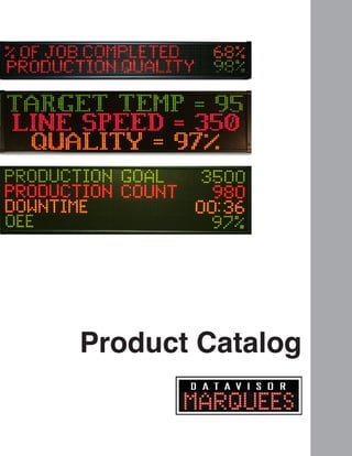
DataVisor Marquee Product Catalog
- 2. To Our Valued Customers, DataVisor Marquees is a leader in quality marquee solutions meeting the demand for cost effective and reliable visualization solutions. Our comprehensive products offer the flexibility to provide customized solutions as well as standardized products. This catalog represents DataVisor Marquees’ years of engineering excellence. The DataVisor Marquees team is committed to helping you stay competitive in your industry. Wishing you great success in your business. Quality Assurance & Reliability: One of DataVisor Marquees primary objectives is to offer outstanding quality. DataVisor Marquees regards quality as a comprehensive procedure in our manufacturing process. Our fully automated testing after assembly ensures the highest level of quality in our products.
- 3. Table of Contents About DataVisor Marquees and Exor 1 About DataVisor Marquees 2 About Exor 3 Vision of DataVisor Marquees 5 DataVisor Marquees Product Series Overview About OEE 7 Definition of OEE 8 OEE Terminology 9 Calculating OEE 10 The Complete Guide to OEE Production Marquee Series 11 Production Marquee Series 12 Set Up and Application Examples 13 Getting Started with the Production Marquee 14 An Example of Calculating OEE Messenger Marquee Series 15 Messenger Marquee Series 16 System Connectivity Solutions 17 Messenger Marquee & UDP Messaging EthernetIP Marquee Series 19 EthernetIP Marquee Series 20 Set Up and Functionality 21 EtherNet/IP Description & Implementation Modbus Marquee Series 23 Modbus Marquee Series 24 Set Up and Functionality 25 Modbus TCP Description & Implementation Selection Chart 27 Part Numbers, Specifications
- 4. About DataVisor Marquees DataVisor Marquees is an engineering company designing, programming and manufacturing visual displays and marquee scoreboards to help improve machine productivity and messaging within a manufacturing facility. Whatever your goal - reducing downtime, increasing productivity or improving quality, DataVisor Marquees can help you reach it. Benefits when implementing a DataVisor Marquee: • Inform & motivate plant personnel • Display production data and key performance indicators (KPIs) • Monitor and collect production data and KPIs • Display production data, alarms and messages using EtherNet/IP • Broadcast production data, alarms and messages via Ethernet UDP • Display production data, alarms and messages using Modbus TCP Our goal is to make marquee signs simple and affordable so that every manufacturing company can implement this tool. Call or visit our website to learn more about our product offering or to have a sales engineer visit your plant. Product knowledge, application assistance and technical support are all available through Exor and their distribution channel. www.datavisormarquees.com 1
- 5. About Exor Exor is a global manufacturer of HMI or operator interfaces. Since 1971, Exor has been producing high quality, innovative and visually appealing HMI solutions. 40+ years of experience has led us to our flagship offer, JMobile configuration software and the 500 & 600 series HMIs. Exor’s modern tool set of software and diplays allows for crafting the best HMI “User Experience” in the industry. Backed by the industry best 5 year warranty, Exor delivers the best value. Exor HMI displays with our visual appeal, superior resolution and modern graphics offer what today’s user expects from a touchscreen device. www.exoramerica.com DataVisor Marquees are distributed through Exor America and their certified channel of distributors located throughout North America. 2
- 6. 3 Vision of DataVisor Marquees When manufacturing companies run up against capacity problems, they immediately look to increase overtime, add shifts or purchase new equipment. Instead, they should look to optimize their existing machines to increase equipment reliability, improve performance and lower overall downtime. Manufacturing plants should spend their valuable time and money on improving their process rather than purchasing new machines. Question: How can a manufacturing company optimize the performance of their existing equipment? Answer: By visualizing data, messages and alarms to benchmark, analyze and improve their manufacturing process. With our flagship product, DataVisor Marquees has designed a product called the Production Marquee to help with this process. The Production Marquee implements the industry tool of OEE (Overall Equipment Effectiveness). The Production Marquee provides managers and machine operators with real-time information to make crucial decisions about the effectiveness of the production process. Plant personnel get a first-hand look at the production process and key information of the machine by viewing data on the Production Marquee. Instead of manually recording this data for end of shift results, manufacturers can monitor, analyze and improve their process in real-time throughout the day. Information is imperative for survival in this global economy. Measuring the efficiency of your process and equipment can yield significant results for your company. Know what motivates your team and the efficiency metrics of your manufacturing process.
- 7. 4 DataVisor Marquees manufactures additional marquee products that provide machine operators and managers with continual line notification and control. Through visualization, actions can be taken to prevent events that cause downtime, slow cycle speeds and produce poor product quality. These marquee products provide the opportunity for operators to view data, messages and alarms related to their production process. DataVisor Marquees invites you to read and educate yourself on our marquee product offering. Whether you are looking to produce OEE data, broadcast OEE data from your data collection software or display OEE data from your PLC, DataVisor Marquees has a marquee product for you. Production Marquees, Messenger Marquees, EthernetIP Marquees and Modbus Marquees are all tools available for installation in your facility to visualize, monitor, and collect data in your plant. DataVisor Marquees require no software to install! SOFTWARE
- 8. 5 DataVisor Marquees Product Series Overview Production Marquee The Production Marquee is a self-contained production scoreboard monitoring KPI variables to be displayed, monitored and collected on the plant floor. In addition, the Production Marquee communicates real time production data over Ethernet to plant personnel within the plant or remotely. With a built-in WEB server, the Production Marquee requires no software to install and setup is done via the intuitive browser based configuration tools. Setup and monitoring of production data is as simple as opening a WEB browser and entering the IP address of the marquee. The Production Marquee’s digital inputs supply the source for displaying data from the 30+ KPI production variables. KPI variables such as Count, Rate, Cycle Time, % Complete, Target Counter, Down Time and OEE can be displayed and monitored on the marquee sign. Production goals reached, machine performance monitored and plant floor information collected are all benefits of installing the Production Marquee. With all of these features and no software to install, the Production Marquee is a necessary piece of production equipment for the growth of any manufacturing plant. Messenger Marquee The Messenger Marquee offers an innovative and simple method to display information on a marquee display via Ethernet. The Messenger Marquee has a built-in WEB server, eliminating the need to install software to program the marquee sign. Setup of the display is as simple as opening the WEB browser on a computer and entering the IP address of the marquee sign. The Messenger Marquee receives broadcasted Ethernet UDP messages from any system supporting UDP (User Datagram Protocol) functionality. ERP, MRP, SCADA and data collection software packages all support UDP. Also, Siemens PLCs have UDP capability and communicate with the Messenger Marquee. The Messenger Marquee can broadcast company information, production goals reached or machine performance data throughout their entire plant floor. With no software or programming required, the Messenger Marquee is a beneficial piece of network equipment to keep communications open in any manufacturing plant.
- 9. 6 EthernetIP Marquee The EthernetIP Marquee revolutionizes the automation industry by improving how a marquee sign should connect and communicate on the Rockwell EtherNet/IP network. With a built-in WEB server, the EthernetIP Marquee requires no software to program the marquee. Setup of the marquee is as simple as opening the web browser on your computer and entering the IP address of the marquee sign. With a fully integrated package, the EthernetIP Marquee is configured to broadcast PLC data and messages without programming communication blocks within the ladder logic code of the Rockwell RSLogix software. The EthernetIP Marquee allows the user to set up the functionality of the marquee sign and simply connect to the Rockwell PLC. The information viewed can range from alarms, machine performance or production data and are selected and displayed through internal registers from the Rockwell PLC. With no software to install, the EthernetIP Marquee is the innovative way for a marquee sign to communicate on the EtherNet/IP network. Modbus Marquee The Modbus Marquee is a marquee sign connecting and communicating over Ethernet on the Modbus network. The Modbus Marquee has a built in WEB server, eliminating the need to install software to program the marquee sign. Setup of the display is as simple as opening a WEB browser on your computer and entering the IP address of the marquee sign. With a fully integrated package, the Modbus Marquee is configured to broadcast Modbus data and messages without programming communication blocks from the Modbus master. The Modbus Marquee allows the user to set up the functionality of the marquee sign and simply connect to the Modbus master. These messages are selected and displayed through internal registers from the Modbus master. The information displayed on the marquee range from alarms, machine performance or production data. With no software to install, the Modbus Marquee stands alone as the best way for a marquee to communicate on the Modbus TCP (Ethernet) network.
- 10. Definition of OEE Overall Equipment Effectiveness (OEE) is a tool to monitor and improve the efficiency of your manufacturing process. Developed in the mid 1990s, OEE has become an accepted management tool to measure and evaluate plant floor productivity. OEE is broken down into three measuring metrics of Availability, Performance and Quality. These metrics help gauge your plant’s efficiency and effectiveness and categorize these key productivity losses that occur within the manufacturing process. OEE empowers manufacturing companies to improve their processes and in turn ensure quality, consistency and productivity measured at the bottom line. By definition, OEE is the calculation of Availability, Performance and Quality. OEE = Availability x Performance x Quality Metric 1: Availability Availability = Run Time / Total Time Definition: Percentage of the actual amount of production time the machine is running to the production time the machine is available. OEE: The total run time of the machine subtracting all unplanned downtime. Metric 2: Performance Performance = Total Count / Target Counter Definition: Percentage of total parts produced on the machine to the production rate of the machine. OEE: How well the machine is running when it is running. Metric 3: Quality Quality = Good Count / Total Count Definition: Percentage of good parts out of the total parts produced on the machine. OEE: How many good parts versus bad parts the machine has produced. 7
- 11. OEE Terminology Listed below are the various plant manufacturing terms that make up OEE and the three metric values (Availability, Performance, Quality) used in the calculation of OEE. 1. RUN TIME (Availability Metric) - The total production time that the machine has been running and producing parts. 2. SETUP TIME (Availability Metric) - The period of time on the machine required for an operator to perform all the necessary tasks to produce the first good part. 3. DOWN TIME (Availability Metric) - The period of time the machine is not available for production due to maintenance or breakdown. 4. TOTAL TIME (Availability Metric) - The total accumulated machine time of Run Time + Down Time + Setup Time. 5. TARGET COUNTER (Performance Metric) - the number of parts or cycles that should be completed at a particular point within the shift, day or production run. 6. TOTAL COUNT (Performance & Quality Metric) - The total number of parts, good and bad, that are produced on the machine. 7. GOOD COUNT (Quality Metric) - The input count for any part produced to manufacturing specifications on the machine. 8. AVAILABILITY = Run Time / Total Time 9. PERFORMANCE = Total Count / Target Counter 10. QUALITY = Good Count / Total Count 8
- 12. Calculating OEE OEE begins with Planned Machine Run Time and measures the productivity of the machine. With reductions from Losses of Down Time, Speed and Quality categories, the formula calculates the Final Machine Run Time of the machine. The OEE metric Availability takes into account any Down Time Losses. The OEE metric Performance takes into account any Speed Losses. The OEE metric Quality takes into account any Quality Losses. Planned Machine Run Time - Reductions from down time losses - Reductions from speed losses - Reductions from quality losses = Final Machine Run Time The overall goal of OEE is to maximize the Final Machine Run Time OEE = Availability x Performance x Quality Availability = Run Time / Total Time Performance = Total Count / Target Counter Quality = Good Count / Total Count 9 Plant Operating Time Planned Machine Run Time Planned Shutdown Total Time Run Time Down Time Losses Target Counter Total Count Speed Losses Total Count Good Count Quality Losses Final Machine Run Time Availability Performance Quality OEE
- 13. 10 The Complete Guide to OEE DataVisor Marquees has published a document to help with understanding and implementing OEE in your manufacturing process. This document is called The Complete Guide to Simple OEE. DataVisor Marquees invites you to read this guide to understand OEE and how to implement this tool in you facility. Above is the cover page of this published document. The complete document can be downloaded at: www.datavisormarquees.com or www.exoramerica.com
- 14. 11 Product Features • NO SOFTWARE TO INSTALL Embedded web server • Integrated production monitoring system • Selection menu of 30+ data source variables • Collect real time data over Ethernet • Store production data to 3rd party spreadsheet • Programmable break and downtime schedules • Variable event driven color changes • OEE Product Specifications • 1, 2, and 4 line alphanumeric display • 13 and 20 character width; tricolor LED • 6 programmable inputs (24 VDC PNP) • Ethernet communication port • 100,000 hour rated LED life • Industrial metal housing • 120 VAC power; 24 VDC (1 line model) Part Number Model Dimensions Weight PM-0113-T (1 line, 13 characters, tricolor) 26.0” x 4.5” x 1.75” 2.8 LBS PM-0213-T (2 line, 13 characters, tricolor) 25.5” x 6.25” x 3.75” 10.8 LBS PM-0220-T (2 line, 20 characters, tricolor) 39.75” x 6.25” x 3.75” 17.9 LBS PM-0420-T (4 line, 20 characters, tricolor) 39.75” x 11.0” x 3.75” 26.2 LBS PRODUCTION MARQUEE SERIES PM-0213-T PM-0220-T PM-0420-T PM-0113-T Ethernet Plant Network
- 15. 12 Production Marquee Set Up and Application Examples OEE (Overall Equipment Effectiveness): This setup of the marquee uses several of the data sources to generate this calculation. Using Machine Availability (run time/total time), Machine Performance (average cycle time/expected cycle time) and Quality (good parts/total parts) calculates the OEE of your process. KPIs (Key Performance Indicators): This setup of the marquee displays production data and process information. Total Count, Rate, Cycle Time and Downtime are several of the selectable KPIs to display on the marquee. KPIs help address your production problems immediately saving setup time and reducing downtime. Machine operators and plant management can view, monitor and collect real time KPIs that inform and motivate from the marquee. Real Time KPIs with Message Call Inputs: In addition to displaying KPIs, this setup of the marquee utilizes inputs to broadcast an “override” message on a selected line of the marquee. Downtime, maintenance, and setup messages can be displayed on the marquee when the corresponding input becomes active. An elapsed timer is also displayed to show how long the manufacturing process has been in this condition. Event Driven Color Changes: This setup of the marquee allows the data source to control color change within the marquee based on percentages of that selected data source. All production data source inputs have this capability. Displayed data sources can be shown in green when on pace, yellow when falling behind, or blinking red when below the required target. Takt Time (Target Counter) Pace Tool: This setup of the marquee is used to help machine operators understand the environment of their manufacturing process. The target counter, a remaining or elapsed takt timer and percent of target counter are all calculated to display the real time process data for both the operator and production supervisor to view on the plant floor. By selecting the “Message Display and Data Source” button, the user can set up the message text, font size, color and functionality of the message to be displayed on the marquee. With proper authorization, the user can enter into the marquee sign setup menu. This web page is where the user has access to the marquee configuration pages used to set up the marquee sign.
- 16. 13 Getting Started with the Production Marquee The Production Marquee Series combines a visual display with Ethernet communications, digital I/O and web server technology integrated into one self-contained package. With no software to install and the data source formulas programmed into the marquee, functionality of the application is selected from browser based configuration tools. Setup and monitoring of this production data is as simple as opening a web browser and entering the IP address of the marquee display. Imagine real time plant floor production data monitored and collected anywhere within your facility. Just supply two inputs, enter your target counter value and the OEE calculation is displayed, monitored and collected by simply choosing OEE as the data source. Additionally, you can select your Goal, Break Schedule and other Production Data Sources that are important to view and monitor from your process. The table below lists the functionality of the Production Marquee. You provide the inputs, select the data sources and the Production Marquee takes care of the rest. Customer Selects DataVisor Marquees Displays, Monitors, and Collects Data Source/ Web Tab One Input Availability, Total Count, % Complete, Rate, Cycle Times, Run Time, Down Time Total Count Second Input Quality, Bad Count, % Bad Bad Count Target Counter Value Performance, OEE, Pace, % of Pace Target Counter Takt Time Interval Target Counter, Takt Time Remaining, Takt Time Elapsed Count/Rate/OEE Target/Goal Goal, % Complete, Pieces to Goal Goal Run Input Monitor Down Time and Run Time Down Time Setup Input Monitor Setup or User Time Setup Time Call Inputs Display Override Messages along with Timer Values Override Messages Break Schedule Select Break Times and Lunch Break Times Break and Down Times
- 17. 14 Machine Data Values Shift Length (8 Hours) 480 Minutes Run Time 375 Minutes Breaks 60 Minutes Setup Time 15 Minutes Down Time 30 Minutes Total Time 420 Minutes Ideal Cycle Time 1 Part Every 63 Seconds Total Count 360 Good Count 355 Target Counter 400 An Example of Calculating OEE The table to the right shows an example of machine production data to help understand the concept of OEE and the calculation of this data. This example will show the calculation of OEE and the OEE Metrics of Availability, Performance and Quality. Production Data (Calculated Values from Production Marquee) Data Source Run Time 375 Total Production Minutes per Shift Run Time Break Times 60 Total Break Minutes per Shift Run Time Down Time 30 Total Downtime Minutes per Shift Down Time Setup Time 15 Total Setup Minutes per Shift Setup Time Total Count 360 Total Parts Produced per Shift Total Count Good Count 355 Good Parts Produced per Shift Bad Count Target Counter 400 Expected Parts per Shift Target Counter Process Data Formula Result Run Time Total Production Time of the Machine 375 Total Time Down Time + Run Time + Setup Time 420 Good Count Total Good Parts Produced on the Machine 355 OEE Variables Formula Result Availability Run Time/Total Time (375/420) 89.29% Performance Total Count/Target Counter (360/400) 90.00% Quality Good Count/Total Count (355/360) 98.61% OEE Availability x Performance x Quality 79.24%
- 18. 15 Product Features • NO SOFTWARE TO INSTALL Embedded web server • UDP message functionality • Selection of 25+ display message methods • Web based message editor and controller • Ethernet communication • Broadcast company information and safety data • Display data and messages from ERP, MRP, and SCADA systems Product Specifications • 1, 2, and 4 line alphanumeric display • 13 and 20 character width • Display 2”, 3” or 4” character height • Tri-color LED characters • 100,000 hour rated LED life • Industrial metal housing • 120 VAC Power; 24 VDC (1 line model) MESSENGER MARQUEE SERIES MM-0220-T MM-0113-T MM-0420-T MM-0213-T Ethernet Wireless Access Point Part Number Model Dimensions Weight MM-0113-T (1 line, 13 characters, tricolor) 26.0” x 4.5” x 1.75” 2.8 LBS MM-0213-T (2 line, 13 characters, tricolor) 25.5” x 6.25” x 3.75” 10.8 LBS MM-0220-T (2 line, 20 characters, tricolor) 39.75” x 6.25” x 3.75” 17.9 LBS MM-0420-T (4 line, 20 characters, tricolor) 39.75” x 11.0” x 3.75” 26.2 LBS Plant Network
- 19. 16 System Connectivity Solutions MRP Systems Siemens PLCsERP Systems SCADA Systems Ethernet Ethernet
- 20. 17 Messenger Marquee & UDP Messaging WHAT IS UDP? User Datagram Protocol (UDP) is one way of sending data over an Ethernet network. Using UDP, programs on network computers can send short messages sometimes known as datagrams to one another. Many of todays PC programming packages along with industrial products such as a PLC support UDP communications. UDP is also designed to support broadcast mode which allows a single message to be sent from a system and then received by multiple devices. How is UDP implemented in the Messenger Marquee? Port The port address used for receiving UDP messages is 2010. Any data received on this port of the Messenger Marquee will be read and displayed on the Messenger Marquee. IP Address Specific If the user wishes to send a message to a given Messenger Marquee on the network, the Marquee’s IP address is used during the message transfer. In the UDP message transmission, the user must supply the IP address of the Messenger Marquee that they wish to send the message. Broadcast Message If the user wishes to send a message to all Messenger Marquees on the network, the user specifies the broadcast IP address (255.255.255.255). Upon sending a message to port 2010 with the broadcast IP address, all Messenger Marquees on the network will display the same message. Formatting Message In the simplest system, the text/data to be displayed is sent to the Messenger Marquee. If nothing more than the text/data is transmitted out the UDP message then the DEFAULT COLOR and DEFAULT DISPLAY METHOD is used to display the text/data. In other cases the user may wish to change the color of certain pieces of text/data or change the manor the message is displayed on the Messenger Marquee. This changing of the default color and display method is accomplished by adding what is called a MODIFIER. A MODIFIER is used to override the default color or display mode of the Messenger Marquee. The user simply inserts the modifier in the message sent and the marquee adjusts the operation accordingly. A modifier always start with an @ follow by a one character code.
- 21. 18 Size Changed Modifiers Size change modifiers may be embedded within the message to change the character size of text/data of the message. If a modifier is included within the message then all text/data following this modifier will be the size specified. Color Changed Modifiers Color change modifiers may be embedded within the message to change the color of text/data of the message. If a modifier is included within the message then all text/data following this modifier will be the color specified. Display Method Modifiers Display Method is the method the marquee displays the received message. There are 26 different ways that a message may be displayed on the marquee. If no modifier is received with the message then the DEFAULT DISPLAY METHOD is used to display the message. The display method modifier is always placed at the beginning of the message. The display method modifier always starts with a ~ followed by a capital letter A to Z. Display methods include scroll, slide, shoot, twinkle and rotate. Examples: 1. Message sent to Marquee: LINE #1@N LINE #2 The Marquee will display LINE #1 on the top line, LINE #2 on the bottom line. 2. Message sent to Marquee: @T The Marquee will display the time of the real time clock of the marquee. 3. Message sent to Marquee: @F FLASH TEST The text FLASH TEST will flash as it is displayed on the marquee. 4. Message sent to Marquee: ~X@4 TEST MESSAGE The message TEST MESSAGE will twinkle on the marquee with 4” size. Modifier Size @2 Text/Data following this modifier will be 2 inch @3 Text/Data following this modifier will be 3 inch @4 Text/Data following this modifier will be 4 inch Modifier Size @R Text/Data following this modifier will be RED @G Text/Data following this modifier will be GREEN @Y Text/Data following this modifier will be YELLOW
- 22. 19 Product Features • NO SOFTWARE TO INSTALL Embedded web server • EtherNet/IP protocol • Direct register access to Rockwell PLCs • Ethernet port for data collection • Broadcast alarms and data from PLCs supporting EtherNet/IP Product Specifications • 1, 2, and 4 line alphanumeric display • 13 and 20 character width • Tri-color LED characters • 100,000 hour rated LED life • Industrial metal housing • 120 VAC power; 24 VDC (1 line model) Part # IP-0220-T Part # IP-0420-T Part # IP-0113-TPart # IP-0213-T Rockwell PLC Part Number Model Dimensions Weight IP-0113-T (1 line, 13 characters, tricolor) 26.0” x 4.5” x 1.75” 2.8 LBS IP-0213-T (2 line, 13 characters, tricolor) 25.5” x 6.25” x 3.75” 10.8 LBS IP-0220-T (2 line, 20 characters, tricolor) 39.75” x 6.25” x 3.75” 17.9 LBS IP-0420-T (4 line, 20 characters, tricolor) 39.75” x 11.0” x 3.75” 26.2 LBS ETHERNETIP MARQUEE SERIES
- 23. 20 Upon entering the IP address of the marquee sign from the web browser, the monitor page is displayed. This web page is where user configured process values and variable data can be viewed. With proper authorization, the user can enter into the marquee sign setup menu. This web page is where the user has access to the marquee configuration pages used to set up the marquee sign. By selecting the “Edit Messages” button, the user can set up the message text, font size, color and functionality of the message to be displayed on the marquee sign. By selecting the “Variable Data Settings” button, the user can set up the variable data from the PLC to be displayed on the marquee. The format of the variable data is entered here. EthernetIP Marquee Set Up and Functionality
- 24. 21 EtherNet/IP Description & Implementation In 2001, EtherNet/IP was introduced. Today, it is a complete industrial ethernet network solution available for manufacturing automation. With rapid growth, Rockwell Automation is harnessing the advantages of ethernet and open technologies. EtherNet/IP is the name given to the Common Industrial Protocol (CIP), as implemented over standard ethernet (IEEE 802.3 and the TCP/IP protocol suite). The “IP” in “EtherNet/ IP” refers to “Industrial Protocol”. EtherNet/IP is a member of a family of networks that implements CIP. EtherNet/IP and CIP are managed by ODVA. ODVA publishes the EtherNet/IP specification and helps ensure compliance through conformance testing. ODVA is an international association comprised of members from the world’s leading automation companies. ODVA and its members support network technologies based on the Common Industrial Protocol (CIP). These include DeviceNet, EtherNet/IP, and ControlNet. ODVA manages the development of these open technologies and assists manufacturers in standards development, certification and industry awareness. EthernetIP Marquee Implementation The EthernetIP Marquee has been designed to work on EtherNet/IP as a Generic Ethernet I/O module. No special Message Blocks or other special programming is required within the PLC to control the marquee. This section will discuss the EtherNet/IP implementation and how to configure the EthernetIP Marquee on an EtherNet/IP network. Require EtherNet/IP Scanner/Master The EthernetIP Marquee is setup as an EtherNet/IP adapter/slave device. A scanner/master device is required to exchange data and message numbers to the marquee. The scanner/master must support EtherNet/IP Class 1 I/O Messaging in order to control the marquee. If the controlling device supports EtherNet/IP I/O control, then the controller can communicate with the EthernetIP Marquee. Typical examples of this are the Rockwell Automation series of controllers. There are other EtherNet/IP controllers available on the market, so consult your manufacturer for specific product specifications.
- 25. EthernetIP Marquee Data Register Map The table below lists the specifications of the EthernetIP Marquee implementation. Output Instance Data Map The table below describes the output instance of the Marquee and gives a description on each attribute of the instance (please consult manual for complete setup). 22 Specification Data Description Vendor ID 119 Exor Vendor ID code Product Type 24 HMI Product Code 1 DataVisor Marquee Revision 1 Product Name DataVisor Marquee Input Assembly Instance 101 4 ints of inputs Output Assembly Instance 102 32 ints of output Configuration Assembly Instance 128 0 Bytes Offset Operation Description 0 Enable Enable Marquee Communications must always be a value of 1 1 Message Register 1 Message number to display or if the marquee is in BIT MESSAGE CALL-UP then controls messages 1-16 2 Message Register 2 Message number to display or if the marquee is in BIT MESSAGE CALL-UP then controls messages 17-32 3 Message Register 3 Message number to display or if the marquee is in BIT MESSAGE CALL-UP then controls messages 33-48 4 Message Register 4 Message number to display or if the marquee is in BIT MESSAGE CALL-UP then controls messages 49-64 5 Variable Data Register 0 For embedding data into message as @ 0 6 Variable Data Register 1 For embedding data into message as @ 1 7 Variable Data Register 2 For embedding data into message as @ 2 8 Variable Data Register 3 For embedding data into message as @ 3 9 Variable Data Register 4 For embedding data into message as @ 4 10 Variable Data Register 5 For embedding data into message as @ 5 11 Variable Data Register 6 For embedding data into message as @ 6 12 Variable Data Register 7 For embedding data into message as @ 7 13 Variable Data Register 8 For embedding data into message as @ 8 15 Variable Data Register 9 For embedding data into message as @ 9
- 26. 23 Product Features • NO SOFTWARE TO INSTALL Embedded web server • Modbus TCP protocol • Direct register access to Modbus masters • Ethernet port for data collection • Broadcast alarms and data from the Modbus master Product Specifications • 1, 2, and 4 line alphanumeric display • 13 and 20 character width • Tri-color LED characters • 100,000 hour rated LED life • Industrial metal housing • 120 VAC power; 24 VDC (1 line model) Part # MB-0220-T Part # MB-0420-T Part # MB-0113-T Part # MB-0213-T Part Number Model Dimensions Weight MB-0113-T (1 line, 13 characters, tricolor) 4.5.0” x 26.0” x 3.75” 2.8 LBS MB-0213-T (2 line, 13 characters, tricolor) 6.25” x 25.5” x 3.75” 10.8 LBS MB-0220-T (2 line, 20 characters, tricolor) 6.25” x 39.75” x 3.75” 17.9 LBS MB-0420-T (4 line, 20 characters, tricolor) 11.0” x 39.75” x 3.75” 26.2 LBS Modbus Master MODBUS MARQUEE SERIES
- 27. 24 Upon entering the IP address of the marquee sign from the web browser, the monitor page is displayed. This web page is where user configured process values and variable data can be viewed. With proper authorization, the user can enter into the marquee sign setup menu. This web page is where the user has access to the marquee configuration pages used to set up the marquee. By selecting the “Variable Data Settings” button, the user can set up the variable data from the PLC to be displayed on the marquee. The format of the variable data is entered here. Modbus Marquee Set Up and Functionality By selecting the “Edit Messages” button, the user can set up the message text, font size, color and functionality of the message to be displayed on the marquee.
- 28. 25 Modbus TCP Description & Implementation In 1979, Modicon developed the Modbus protocol for industrial automation systems and Modicon PLCs. It has become an industry standard for the transfer of I/O information and register data between industrial and monitoring devices. Modbus is a widely accepted open protocol and supported by many manufacturers. Modbus devices communicate using a master-slave (client-server) technique in which one device (master/client) can initiate transactions (called queries). The other devices (slaves/ servers) respond by taking the action requested in the query. The slave/server in our application is the marquee sign. Masters can address individual slaves, or can initiate a broadcast message to all slaves. Slaves do not initiate messages on their own. They only respond to queries from the master. Modbus TCP (Transmission Control Protocol) is simply the Modbus RTU protocol with a TCP interface that runs on Ethernet. Just as with Ethernet, Modbus TCP is accessible to anyone. It is widely supported by many manufacturers of industrial equipment including DataVisor Marquees. Modbus Marquee Implementation The Modbus Marquee has been designed to work on Modbus TCP. No special message blocks or other special programming is required within the controller to communicate with the Modbus Marquee. This section will discuss the Modbus Marquee implementation and how to configure the marquee on an Modbus TCP network. Require Modbus Client Master Because the Modbus Marquee is setup as a Modbus server/slave device, a client/ master device is required to exchange data and message numbers to the marquee. The client/master must support Modbus TCP in order to control the marquee. If the controlling device supports Modbus TCP, then the controller can display messages on the Modbus Marquee. Modbus & Ethernet Connection The Modbus Marquee is equipped with an Ethernet port. The plant Ethernet port is used for configuration and monitoring over the plant network.
- 29. Modbus Marquee Data Register Map The table below describes the Modbus Register Map of the Modbus Marquee and gives a description of each Modbus Holding Register (please consult manual for complete setup). Note 1: In the marquee configuration, the message registers can be set as a BIT message call up. In this case, the marquee will look at the bits within that last register, bit 1-16 to display the corresponding message. Note 2: To embed data into the message, insert the @ sign followed by the number of the variable data register. For example, “ this is my message with value @3 ” will display the message with the value in Holding Register 40008. Setup Menu The setup menu allows the user to access the Modbus Marquee configuration pages. This page consists of 8 configuration page access buttons. 26 Modbus Holding Register Operation Description 40001 Message Control Register 1 Modbus register to enter message number to display 40002 Message Control Register 2 Modbus register to enter message number to display 40003 Message Control Register 3 Modbus register to enter message number to display 40004 Message Control Register 4 Modbus register to enter message number to display 40005 Variable Data Register 0 For embedding data into message as @ 0 40006 Variable Data Register 1 For embedding data into message as @ 1 40007 Variable Data Register 2 For embedding data into message as @ 2 40008 Variable Data Register 3 For embedding data into message as @ 3 40009 Variable Data Register 4 For embedding data into message as @ 4 40010 Variable Data Register 5 For embedding data into message as @ 5 40011 Variable Data Register 6 For embedding data into message as @ 6 40012 Variable Data Register 7 For embedding data into message as @ 7 40013 Variable Data Register 8 For embedding data into message as @ 8 40014 Variable Data Register 9 For embedding data into message as @ 9
- 30. 27 Part Number PM-0113-T PM-0213-T PM-0220-T PM-0420-T MM-0113-T MM-0213-T MM-0220-T Display Capacity - 2” characters 1 line of 13 2 lines of 13 2 lines of 20 4 lines of 20 1 line of 13 (156 character max) 2 lines of 13 (156 character max) 2 lines of 20 (156 character max) Display Capacity - 3” characters N/A N/A N/A 3 lines of 15 N/A N/A N/A Display Capacity - 4” characters N/A 1 line of 8 1 line of 13 2 lines of 13 N/A 1 line of 8 (156 character max) 1 line of 13 (156 character max) Display Type Tri-Color LED Tri-Color LED Tri-Color LED Tri-Color LED Tri-Color LED Tri-Color LED Tri-Color LED Data Source Digital Inputs Digital Inputs Digital Inputs Digital Inputs Ethernet UDP Ethernet UDP Ethernet UDP Communications Ports Ethernet Ethernet Ethernet Ethernet Ethernet Ethernet Ethernet Voltage Requirements 24 VDC 120 VAC 120 VAC 120 VAC 24 VDC 120 VAC 120 VAC Power Requirements (Max) 2 Amps .8 Amp 1 Amp 2 Amps 2 Amps .8 Amp 1 Amp Dimensions (L x H x D) 26.0” x 4.5” x 1.75” 25.5” x 6.25” x 3.75” 39.75” x 6.25” x 3.75” 39.75” x 11.0” x 3.75” 26.0” x 4.5” x 1.75” 25.5” x 6.25” x 3.75” 39.75” x 6.25” x 3.75” Weight 2.8 lbs 10.8 lbs 17.9 lbs 26.2 lbs 2.8 lbs 10.8 lbs 17.9 lbs Selection Chart - Part Numbers, Dimensions SOFTWARE
- 31. MM-0420-T MB-0113-T MB-0213-T MB-0220-T MB-0420-T IP-0113-T IP-0213-T IP-0220-T IP-0420-T 4 lines of 20 (156 character max) 1 line of 13 2 lines of 13 2 lines of 20 4 lines of 20 1 line of 13 (80 character max) 2 lines of 13 (80 character max) 2 lines of 20 (80 character max) 4 lines of 20 (80 character max) 3 lines of 15 (156 character max) N/A N/A N/A 3 lines of 15 N/A N/A N/A 3 lines of 15 (80 character max) 2 lines of 13 (156 character max) N/A 1 line of 8 1 line of 13 2 lines of 13 N/A 1 line of 8 (80 character max) 1 line of 13 (80 character max) 2 lines of 13 (80 character max) Tri-Color LED Tri-Color LED Tri-Color LED Tri-Color LED Tri-Color LED Tri-Color LED Tri-Color LED Tri-Color LED Tri-Color LED Ethernet UDP Modbus TCP Modbus TCP Modbus TCP Modbus TCP EtherNet/IP EtherNet/IP EtherNet/IP EtherNet/IP Ethernet Ethernet Ethernet Ethernet Ethernet Ethernet + EtherNet/IP Ethernet + EtherNet/IP Ethernet + EtherNet/IP Ethernet + EtherNet/IP 120 VAC 24 VDC 120 VAC 120 VAC 120 VAC 24 VDC 120 VAC 120 VAC 120 VAC 2 Amps 2 Amps .8 Amp 1 Amp 2 Amps 2 Amps .8 Amp 1 Amp 2 Amps 39.75” x 11.0” x 3.75” 26.0” x 4.5” x 1.75” 25.5” x 6.25” x 3.75” 39.75” x 6.25” x 3.75” 39.75” x 11.0” x 3.75” 26.0” x 4.5” x 1.75” 25.5” x 6.25” x 3.75” 39.75” x 6.25” x 3.75” 39.75” x 11.0” x 3.75” 26.2 lbs 2.8 lbs 10.8 lbs 17.9 lbs 26.2 lbs 2.8 lbs 10.8 lbs 17.9 lbs 26.2 lbs 28
- 32. EXOR America 10150 International Blvd. Cincinnati, Ohio 45246 (513) 874 - 0900 www.exoramerica.com info@exoramerica.com DataVisor Marquees are distributed through Exor America and their certified channel of distributors located throughout North America. CAT# JAN2016