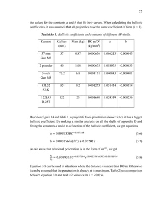
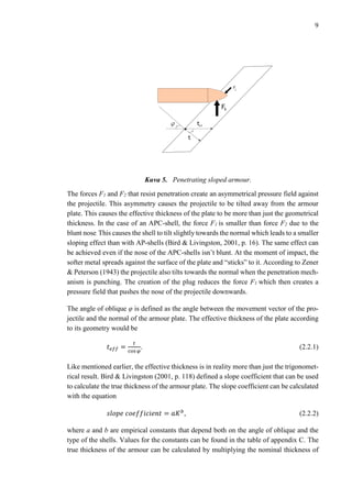
This document discusses the mechanisms of armour penetration by kinetic projectiles. There are three main mechanisms of penetration: dishing, punching, and ductile hole enlargement. Dishing occurs when the projectile diameter is much larger than the armour thickness. Punching requires a blunt impact and very high shear stresses. Ductile hole enlargement is the dominant mechanism when the projectile diameter is close to the armour thickness. The ability of a projectile to penetrate armour depends on its kinetic energy, which is determined by its mass and velocity. The shape and material properties of both the projectile and armour also influence penetration. Mathematical models can predict penetration based on these factors.

![5
hole. This molten metal acts as a lubricant which then reduces the friction. Both Zener &
Peterson (1943) and Rosenberg & Dekel (2012, p. 96) note that friction uses only a small
amount of the total kinetic energy of the projectile. The majority of the energy is used to
deform the armour plate and the projectile. According to Thomson (1955), the amount of
energy required to create the molten layer of metal during perforation is
𝑊𝑞 = 2𝜋𝜇𝑡𝑣 (
𝜎 𝜀 𝐷𝑙
16𝑣
+
3𝜌 𝑝 𝐷3 𝑣
64𝑙
), (2.5)
where µ is the coefficient of friction, which is roughly 0.02. Thomson also estimated that
the thickness h of the molten layer can be expressed with the equation
3
8
𝜋𝐷2
ℎ =
𝑊𝑞
285𝑇 𝑚
, (2.6)
where Tm is the required change in temperature to melt the material of the armour.
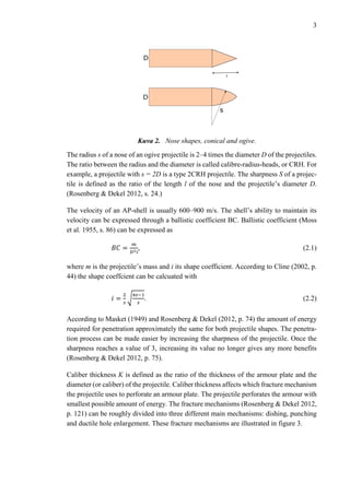
In a situation where the projectile does not penetrate the armour, it shatters against the
surface or bounces away. A failed penetration usually leaves a pit or a dent on the surface
of the armour plate and in some cases it can cause the inside layer of the armour plate to
spall. During impact, the pressure waves reflect from the back of the armour plate, which
causes tension on its surface. This tension can cause cleaving, chipping and fracturing,
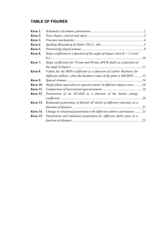
which are often referred to as spalling. (Rosenberg & Dekel 2012, s. 39–42.)
Kuva 4. Spalling (Rosenberg & Dekel, 2012 s. 40).
The spalling of an aluminous plate caused by a glass ball can be seen in figure 5. Accord-
ing to Rosenberg & Dekel (2012, pp. 39–42) the spall strength of a material can be esti-
mated with
𝜎𝑠𝑝𝑎𝑙𝑙 =
2𝜎 𝜀
3
[2 + ln (
𝐸
3(1−𝛾)𝜎 𝜀
)], (2.7)
where γ is the Poisson’s constant of the material and E its Young’s modulus. The formula
gives values close to real life empirical values according to Rosenberg & Dekel.](https://image.slidesharecdn.com/1382d8a3-149b-45b2-a638-ed749ba61a9a-160424132427/85/Mechanisms-of-Armour-Penetration-10-320.jpg)
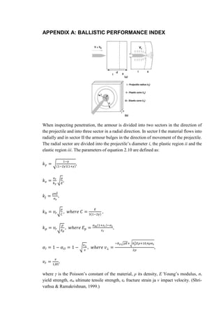
![6
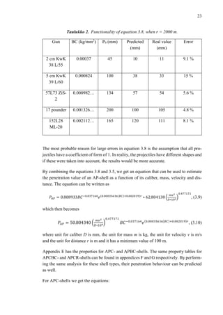
The ability of a material to resist penetration can be estimated through multiple ways. The
most common way is with the ballistic limit velocity. Ballistic limit velocity is the veloc-
ity of a projectile that it needs to penetrate an armour plate of certain thickness. In order
to define the ballistic limit velocity, the material parameters of both the projectile and
armour are needed. According to Rosenberg & Dekel (2012, pp. 117–120) ballistic limit
velocity can be calculated with
𝑣 𝑏𝑙 = √
2𝑡𝜎 𝑟
𝜌 𝑝 𝐿
, (2.8)
where L is the length of the projectile and σr is penetration strength. Penetration strength
characterises the armour’s ability to resist penetration. Penetration strength is dependent
on caliber thickness and it can be divided in to three different forms:
𝜎𝑟 =
{
(
2
3
+ 4𝐾) 𝜎𝜀 , 𝐾 ≤
1
3
2𝜎𝜀 ,
1
3
< 𝐾 ≤ 1
(2 + 0,8 ln 𝐾)𝜎𝜀 , 𝐾 > 1
. (2.9)
Rosenberg & Dekel (2012, s. 120) note, that the values for ballistic limit velocity calcu-
lated through the formula 2.8 differ from real life empirical values by ±2.5 %.
The suitability of a material as an armouring material can be measured by the ballistic
performance index BPI created by Srivathsa and Ramakrishnan (1997). BPI is a dimen-
sionless number and it can be used to compare different materials and different impact
velocities. BPI can be calculated with
Φ = [
𝛼 𝐼
2(1+𝑘 𝑏)2
+ 𝛼𝐼𝐼
(1+𝑘 𝑒)2 𝑘 𝛾
2
2𝑘 𝑗
2 +
1
𝑘 𝑗
(1 +
1
𝑘 𝑝
) +
1
2𝑘 𝑝
2 +
1
2
(1 +
1
𝑘 𝑝
)
2
]. (2.10)
In the equation the first two terms describe the material’s elastic behaviour, the next two
its plastic behaviour and the last term includes the kinetic energy. Explaining the param-
eters ki is not necessary for this work and equation 2.10 is defined more in-depth in ap-
pendix A. However, the index is dependent on the mechanical properties of the material
and the impact velocity, so the index can be defined as a function in the form of
Φ = Φ(𝐸, 𝜌, 𝜎𝜀, 𝜎 𝑚, 𝜀 𝑟, 𝑣), (2.11)
where εr is fracture strain. Based on the BPI, Srivathsa & Ramakrishnan (1999) created
ballistic performance maps. The maps were created as a function of yield strength and
strain hardening rate. The strain hardening rate for a material can be derived from its other
material values and it can calculated with the following equation:
𝐻 =
𝜎 𝑚(1+𝜀 𝑟)−𝜎 𝜀
𝜀 𝑟
. (2.12)](https://image.slidesharecdn.com/1382d8a3-149b-45b2-a638-ed749ba61a9a-160424132427/85/Mechanisms-of-Armour-Penetration-11-320.jpg)
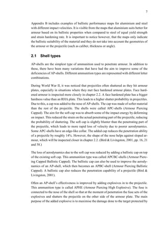
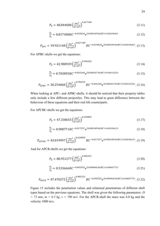
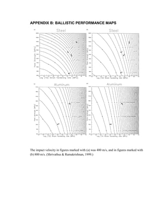
![14
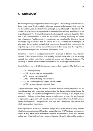
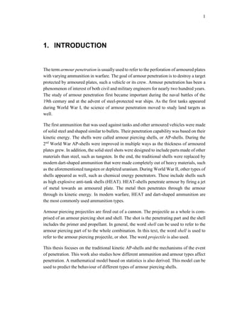
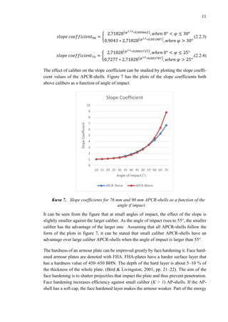
Kuva 9. Spaced Armour..
According to Bird & Livingston (2001, p. 36) a single plate that is equivalent to a certain
spaced armour combination can be calculated with Okun’s equation
𝑡 𝑒𝑓𝑓 = [(1,15𝑡1)1,4
+ 𝐴1,4
𝑡2
1,4
]
1
1,4
, (2.2.6)
where t1 and t2 are the thickness of the primary and secondary plates and A is a constant
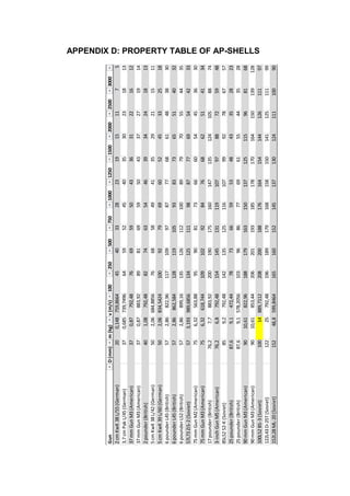
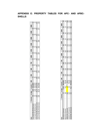
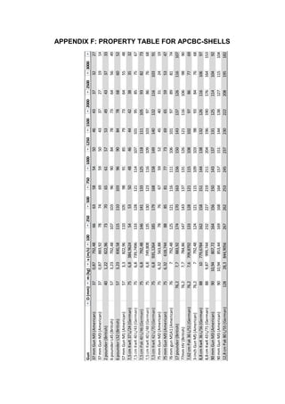
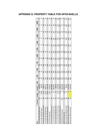
that is dependent on the type of shell and armour. A is 1 if the shell type is APC, APBC
or APCBC. If the shell is an AP-shell, A is 1.05. If the primary plate is face hardened and
the secondary plate is homogeneous, A is 1.10. By looking at the equation, it can be seen
that regardless of the value of A, the primary plate has a larger impact on the effective
thickness of the plate. If the impacts against the primary and secondary plates are not
perpendicular, the thickness of the single plate can be estimated with the slope coeffi-
cients of equation 2.2.2. Once the angle have been taken into account, the effective thick-
ness can be calculated with equation 2.2.6.
Figure 10 illustrates the contour curves of equation 2.2.6 as a function of plate thicknesses
in all three cases. The figure also includes the contours of the unified thickness of the
plates (𝑡1 + 𝑡2). It can be seen from the figure that spaced armour is slightly better than a
single plate if the primary plate is noticeably thicker than the secondary plate. For exam-
ple, a primary plate of 36.0 mm and a secondary plate of 2.0 mm, would equal to a single
plate of 41.8 mm, 40.2 mm or 40.3 mm depending on the value of A. In the case of both
the AP-shells and the face hardened primary plate, the effective thickness can be made
stronger than the unified thickness when the primary plate is noticeably thinner than the
secondary plate. In all the cases where the spaced armour combination has better effective
thickness than a single plate of their unified thickness, the difference in these thicknesses](https://image.slidesharecdn.com/1382d8a3-149b-45b2-a638-ed749ba61a9a-160424132427/85/Mechanisms-of-Armour-Penetration-19-320.jpg)
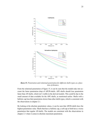
![17
strengthen an already existing armour plate. Bird & Livingston (2001, pp. 38–39) define
three methods of calculating the effective thickness of layered armour. The first method
is based on tests made by the US Navy and the statistical analysis of their results. The
effective thickness of layered armour is then
𝑡 𝑒𝑓𝑓,𝑠𝑡𝑎𝑡 = (𝑡1 + 𝑡2) [0,3129 (
𝑡1
𝑡2
)
0,02527
∗ (𝑚𝑎𝑥(𝑡1, 𝑡2))
0,2439
]. (2.2.7)
The equation has a both minimum and maximum value. The minimum and maximum
values for the equation are
𝑡 𝑒𝑓𝑓,𝑠𝑡𝑎𝑡,𝑚𝑖𝑛 = 0,3 ∗ min(𝑡1, 𝑡2) + max(𝑡1, 𝑡2) (2.2.8)
𝑡 𝑒𝑓𝑓,𝑠𝑡𝑎𝑡,𝑚𝑎𝑥 = 0,96(𝑡1 + 𝑡2). (2.2.9)
In the equations the function max(x1,x2) evaluates as the larger number inside the paren-
theses and min(x1,x2) evaluates as the smaller of the values. The second way of calculating
the effective is through the navy rule of thumb, which is
𝑡 𝑒𝑓𝑓,𝑛𝑎𝑣𝑦 = 0,7𝑡1 + 𝑡2. (2.2.10)
The third way is to use Nathan Okun’s equation. Okun’s layered armour equation is based
on the average of the spaced armour equation and the unified thickness of the plates.
Okun’s layered armour equation is in the form of
𝑡 𝑒𝑓𝑓.𝑂𝑘𝑢𝑛 = 0,5 ∗ [(𝑡1 + 𝑡2) + (𝑡1
1,4
+ 𝑡2
1,4
)
1
1,4
]. (2.2.11)
It is important to notice that Okun’s equation doesn’t take into account which of the plates
is thicker. For example, a 40 mm primary plate and a 20 mm secondary plate get an ef-
fective thickness of 47 mm through the statistical method, 48 mm through the navy rule
of thumb and 55 mm through Okun’s equation. The same plates in the reverse order would
get thicknesses of 45 mm, 54 mm and 55 mm respectively. The exact effective thickness
is difficult to evaluate but it can be stated that the effective thickness is between the uni-
fied thickness of the plates and the thickness of the thicker plate.](https://image.slidesharecdn.com/1382d8a3-149b-45b2-a638-ed749ba61a9a-160424132427/85/Mechanisms-of-Armour-Penetration-22-320.jpg)