1. Report for Rail Cart
Group Members
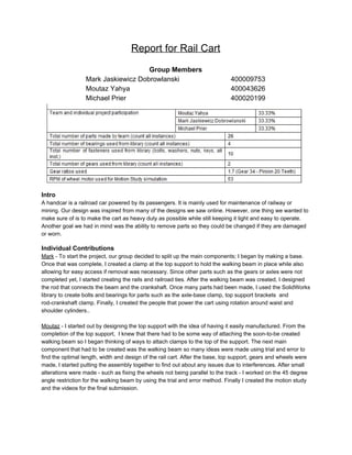
Mark Jaskiewicz Dobrowlanski 400009753
Moutaz Yahya 400043626
Michael Prier 400020199
Intro
A handcar is a railroad car powered by its passengers. It is mainly used for maintenance of railway or
mining. Our design was inspired from many of the designs we saw online. However, one thing we wanted to
make sure of is to make the cart as heavy duty as possible while still keeping it light and easy to operate.
Another goal we had in mind was the ability to remove parts so they could be changed if they are damaged
or worn.
Individual Contributions
Mark - To start the project, our group decided to split up the main components; I began by making a base.
Once that was complete, I created a clamp at the top support to hold the walking beam in place while also
allowing for easy access if removal was necessary. Since other parts such as the gears or axles were not
completed yet, I started creating the rails and railroad ties. After the walking beam was created, I designed
the rod that connects the beam and the crankshaft. Once many parts had been made, I used the SolidWorks
library to create bolts and bearings for parts such as the axle-base clamp, top support brackets and
rod-crankshaft clamp. Finally, I created the people that power the cart using rotation around waist and
shoulder cylinders..
Moutaz - I started out by designing the top support with the idea of having it easily manufactured. From the
completion of the top support, I knew that there had to be some way of attaching the soon-to-be created
walking beam so I began thinking of ways to attach clamps to the top of the support. The next main
component that had to be created was the walking beam so many ideas were made using trial and error to
find the optimal length, width and design of the rail cart. After the base, top support, gears and wheels were
made, I started putting the assembly together to find out about any issues due to interferences. After small
alterations were made - such as fixing the wheels not being parallel to the track - I worked on the 45 degree
angle restriction for the walking beam by using the trial and error method. Finally I created the motion study
and the videos for the final submission.
2. Michael - I began by creating the wheels with a very simple design and made it more complex later in the
project, after the wheels I created the axles and then began to think of ways to mount the gears to the rear
axle and came up with welding a hub to the axle with a key slot in it and then made a shoulder hub which is
also welded to the axle and has holes so that bolts can be screwed into the gear so it doesn't move side to
side. I determined the gear ratio and made the gear and pinion and then made the crankshaft which the
pinion attached to. For the pinion I made a hub which was the same design as the rear axle just a different
size. I made the brackets which attached to the base and hold the crankshaft in place. Once most of the
parts were done, I began to use the Solidworks library to create some bolts and bearings which would
secure the crankshaft and walking beam and the bolts that went into the gears. I inserted all the bolts and
bearings on the assembly and then made the exploded view.
Achievements
As a group we were able to achieve and learn about new concepts involving SolidWorks. Not only have we
been able to strengthen our skills in 3D CAD, our group has also accomplished aspects of design that allows
us to understand better ways of teamwork communication, time managements and prioritizing parts of a
project. One thing our group accomplished was staying on track of the project and keeping motivated, this
included days where hours were spent on designing small objects with multiple setbacks..
Set Backs
As the design furthered, our group noticed we had to constantly improve simple parts we started out with.
Since the parts were all being made separately, we reached a point where the parts had to be combined but
they wouldn’t work properly. An example of this was when the base was created but we didn’t account for
the removal of the axles. Further steps were taken to add bolts and clamps that would allow for the easy
removal of the parts if it was necessary in real life applications.
A major setback in our design was that our group did not account for the 45 degree angle in the beginning of
the walking beam sketches which resulted in time spent changing the rod, crankshaft, gears and walking
beam later on. Not only were some parts not able to fit but objects such as the top support and base had
collisions once we neared the 45 degree angle. It was also an issue that we decided to use a trial and error
method instead of carefully sitting down and calculating angles and lengths to figure out the most effective
way of having the beam move 90 degrees in total.
Conclusion
The team benefited a lot from working on this project overall. The amount of time spent on doing the many
small parts taught us more about SolidWorks and its many features. Our group was also able to learn more
about teamwork and working together on design projects.