SlideShare a Scribd company logo
1 of 167
Download to read offline
Copyright © 2012 by Ceragon Networks Ltd. All rights reserved.
ETSI Version
FibeAir® IP-10 E-Series
Product Description
April 2012
Hardware Release: R3
Software Release: i6.8
Document Revision Fa
FibeAir® IP-10 E-Series Product Description
Ceragon Proprietary and Confidential Page 2 of 167
Notice
This document contains information that is proprietary to Ceragon Networks Ltd. No part of this
publication may be reproduced, modified, or distributed without prior written authorization of
Ceragon Networks Ltd. This document is provided as is, without warranty of any kind.
Registered Trademarks
Ceragon Networks® is a registered trademark of Ceragon Networks Ltd. FibeAir® is a registered
trademark of Ceragon Networks Ltd. CeraView® is a registered trademark of Ceragon Networks
Ltd. Other names mentioned in this publication are owned by their respective holders.
Trademarks
CeraMap™, PolyView™, EncryptAir™, ConfigAir™, CeraMon™, EtherAir™, and MicroWave Fiber™,
are trademarks of Ceragon Networks Ltd. Other names mentioned in this publication are owned
by their respective holders.
Statement of Conditions
The information contained in this document is subject to change without notice. Ceragon
Networks Ltd. shall not be liable for errors contained herein or for incidental or consequential
damage in connection with the furnishing, performance, or use of this document or equipment
supplied with it.
Open Source Statement
The Product may use open source software, among them O/S software released under the GPL or
GPL alike license ("GPL License"). Inasmuch that such software is being used, it is released under
the GPL License, accordingly. Some software might have changed. The complete list of the
software being used in this product including their respective license and the aforementioned
public available changes is accessible on http://www.gnu.org/licenses/.
Information to User
Any changes or modifications of equipment not expressly approved by the manufacturer could
void the user’s authority to operate the equipment and the warranty for such equipment.
FibeAir® IP-10 E-Series Product Description
Ceragon Proprietary and Confidential Page 3 of 167
Revision History
Rev Date Author Description Approved by Date
A November 8, 2011 Baruch Gitlin First revision for release 6.8. Tomer Carmeli November 8, 2011
B November 17,
2011
Baruch Gitlin Added waveguide flanges table for
1500HP/RFU-HP and revised
1500HP/RFU-HP transmit power
specifications.
Tomer Carmeli/Rami
Lerner
November 17,
2011
C November 27,
2011
Baruch Gitlin Added mechanical, environmental,
and electrical specifications for
RFUs and revised Protection
Options section.
Tomer Carmeli/Rami
Lerner
November 27,
2011
D February 8, 2012 Baruch Gitlin Revised RFU-C and 1500HP/RFU-
HP specifications.
Rami Lerner February 8, 2012
E March 15, 2012 Baruch Gitlin Revise PDV value for PTP
optimized transport.
Tomer Carmeli March 15, 2012
F April 2, 2012 Baruch Gitlin Revise RFU-C frequency
specifications.
Rami Lerner April 2, 2012
FibeAir® IP-10 E-Series Product Description
Ceragon Proprietary and Confidential Page 4 of 167
Table of Contents
1. About This Guide............................................................................................ 14
2. What You Should Know ................................................................................. 14
3. Target Audience ............................................................................................. 14
4. Related Documents........................................................................................ 14
5. Section Summary ........................................................................................... 15
6. Product Overview ........................................................................................... 16
6.1 IP-10E Highlights ......................................................................................................... 17
6.1.1 Best Utilization of Spectrum Assets ............................................................................. 17
6.1.2 Spectral Efficiency........................................................................................................ 17
6.1.3 Radio Link .................................................................................................................... 17
6.1.4 Wireless Network ......................................................................................................... 18
6.1.5 Scalability ..................................................................................................................... 18
6.1.6 Availability .................................................................................................................... 19
6.1.7 Network Level Optimization ......................................................................................... 19
6.1.8 Network Management .................................................................................................. 19
6.1.9 Power Saving Mode High Power Radio....................................................................... 20
6.2 Hardware Description................................................................................................... 21
6.2.1 Dimensions and Voltage Rating................................................................................... 21
6.2.2 Front Panel Interfaces.................................................................................................. 21
6.2.3 Available Assembly Options * ...................................................................................... 22
6.2.4 RFU Options................................................................................................................. 22
6.3 Licensing ...................................................................................................................... 23
6.3.1 Working with License Keys .......................................................................................... 23
6.3.2 Licensed Features........................................................................................................ 23
6.4 Radio Configuration Options........................................................................................ 25
6.5 Feature Overview......................................................................................................... 26
6.5.1 General Features ......................................................................................................... 26
6.5.2 Capacity-Related Features .......................................................................................... 26
6.5.3 Ethernet Features ........................................................................................................ 27
6.5.4 Synchronization Features ............................................................................................ 28
6.5.5 Security Features ......................................................................................................... 28
6.5.6 Management Features ................................................................................................. 29
7. Functional Description................................................................................... 31
7.1 Functional Overview..................................................................................................... 32
7.2 IDU Interfaces .............................................................................................................. 33
7.2.1 Ethernet Interfaces....................................................................................................... 33
7.2.2 Additional Interfaces..................................................................................................... 34
7.2.3 Power Options.............................................................................................................. 34
7.3 Nodal Configuration ..................................................................................................... 35
7.3.1 Nodal Configuration Benefits ....................................................................................... 35
7.3.2 IP-10E Nodal Design.................................................................................................... 35
FibeAir® IP-10 E-Series Product Description
Ceragon Proprietary and Confidential Page 5 of 167
7.3.3 Nodal Enclosure Design............................................................................................... 36
7.3.4 Nodal Management...................................................................................................... 37
7.3.5 Centralized System Features....................................................................................... 38
7.3.6 Ethernet Connectivity in Nodal Configurations ............................................................ 38
7.4 Protection Options........................................................................................................ 39
7.4.1 1+1 HSB Protection...................................................................................................... 39
7.4.2 2+0 Multi-Radio and 2+0 Multi-Radio with IDU and Line Protection............................ 41
7.4.3 2+2 HSB Protection...................................................................................................... 41
8. Main Features ................................................................................................. 43
8.1 Adaptive Coding and Modulation (ACM)...................................................................... 44
8.1.1 Eight Working Points.................................................................................................... 44
8.1.2 Hitless and Errorless Step-by-Step Adjustments......................................................... 45
8.1.3 Configurable Minimum ACM Profile............................................................................. 45
8.1.4 ACM Benefits ............................................................................................................... 45
8.1.5 ACM and Built-In Quality of Service............................................................................. 46
8.1.6 ACM with Adaptive Transmit Power ............................................................................ 46
8.2 Multi-Radio ................................................................................................................... 48
8.2.1 IDU and Line Protection in Multi-Radio........................................................................ 49
8.3 XPIC Support ............................................................................................................... 50
8.3.1 XPIC Benefits............................................................................................................... 50
8.3.2 XPIC Implementation ................................................................................................... 51
8.3.3 XPIC and Multi-Radio................................................................................................... 52
8.4 Space and Frequency Diversity ................................................................................... 53
8.4.1 Baseband Switching (BBS) Frequency Diversity......................................................... 54
8.4.2 Baseband Switching (BBS) Space Diversity................................................................ 54
8.4.3 IF Combining (IFC)....................................................................................................... 55
8.4.4 Diversity Type Comparison.......................................................................................... 55
8.5 LTE-Ready Latency ..................................................................................................... 56
8.5.1 Benefits of IP-10E’s Top-of-the-Line Low Latency....................................................... 56
8.6 Carrier Grade Ethernet................................................................................................. 57
8.6.1 Carrier Ethernet Services Based on IP-10E ................................................................ 58
8.6.2 Carrier Ethernet Services Based on IP-10E - Node Failure ........................................ 59
8.7 Ethernet Switching ....................................................................................................... 60
8.7.1 Smart Pipe Mode ......................................................................................................... 60
8.7.2 Managed Switch Mode................................................................................................. 61
8.7.3 Metro Switch Mode ...................................................................................................... 61
8.8 Integrated QoS Support ............................................................................................... 62
8.8.1 QoS Overview .............................................................................................................. 62
8.8.2 IP-10E Standard QoS .................................................................................................. 63
8.8.3 QoS Traffic Flow in Smart Pipe Mode.......................................................................... 63
8.8.4 QoS Traffic Flow in Managed Switch and Metro Switch Mode.................................... 64
8.8.5 Enhanced QoS............................................................................................................. 64
8.8.6 Weighted Random Early Detection.............................................................................. 65
8.8.7 Standard and Enhanced QoS Comparison.................................................................. 67
8.8.8 Enhanced QoS Benefits............................................................................................... 67
8.9 Spanning Tree Protocol (STP) Support ....................................................................... 68
8.9.1 RSTP ...................................................................................................................... 68
FibeAir® IP-10 E-Series Product Description
Ceragon Proprietary and Confidential Page 6 of 167
8.9.2 Carrier Ethernet Wireless Ring-Optimized RSTP ........................................................ 68
8.9.3 Ring-Optimized RSTP Limitations................................................................................ 69
8.9.4 Basic IP-10E Wireless Carrier Ethernet Ring Topology Examples.............................. 70
8.9.4.1 IP-10E Wireless Carrier Ethernet Ring with Dual-Homing .......................... 70
8.9.4.2 IP-10E Wireless Carrier Ethernet Ring - 1+0 .............................................. 71
8.9.4.3 IP-10E Wireless Carrier Ethernet Ring - Aggregation Site.......................... 71
8.10 Ethernet Line Protection............................................................................................... 72
8.10.1Multi-Unit LAG.............................................................................................................. 73
8.10.2Ethernet Line Protection Comparison .......................................................................... 73
8.11 Asymmetrical Scripts.................................................................................................... 74
8.12 Synchronization Support.............................................................................................. 76
8.12.1Wireless IP Synchronization Challenges ..................................................................... 76
8.12.2Precision Timing-Protocol (PTP).................................................................................. 77
8.12.3Synchronous Ethernet (SyncE).................................................................................... 77
8.12.4IP-10E Synchronization Solution ................................................................................. 78
8.12.5Synchronization Using Precision Timing Protocol (PTP) Optimized Transport ........... 79
8.12.6Native Sync Distribution Mode..................................................................................... 80
8.12.6.1 Native Sync Distribution Examples.............................................................. 81
8.12.7SyncE “Regenerator” Mode ......................................................................................... 83
9. RFU Descriptions ........................................................................................... 84
9.1 RFU Selection Guide ................................................................................................... 85
9.2 RFU-C .......................................................................................................................... 86
9.2.1 Main Features of RFU-C.............................................................................................. 86
9.2.2 RFU-C Frequency Bands............................................................................................. 87
9.2.3 RFU-C Mechanical, Electrical, and Environmental Specifications............................... 98
9.2.4 Mediation Device Losses ............................................................................................. 99
9.2.5 RFU-C Antenna Connection ........................................................................................ 99
9.2.6 RFU-C Waveguide Flanges ....................................................................................... 100
9.3 1500HP/RFU-HP........................................................................................................ 101
9.3.1 Main Features of 1500HP/RFU-HP ........................................................................... 101
9.3.2 1500HP/RFU-HP Frequency Bands .......................................................................... 102
9.3.3 1500HP/RFU-HP Mechanical, Electrical, and Environmental Specifications ............ 103
9.3.4 1500HP/RFU-HP Installation Types........................................................................... 104
9.3.5 1500HP/RFU-HP Supported Configurations.............................................................. 104
9.3.6 1500HP/RFU-HP All-Indoor Configurations............................................................... 105
9.3.7 Branching Networks ................................................................................................... 105
9.3.7.1 Split Mount Branching Loss....................................................................... 106
9.3.7.2 All-Indoor Branching Loss ......................................................................... 107
9.3.8 1500HP/RFU-HP Waveguide Flanges....................................................................... 108
9.4 RFH-HS...................................................................................................................... 109
9.4.1 Main Features of RFU-HS.......................................................................................... 109
9.4.2 RFU-HS Frequency Bands ........................................................................................ 110
9.4.3 RFU-HS Mechanical, Electrical, and Environmental Specifications .......................... 111
9.4.4 RFU-HS Antenna Types ............................................................................................ 112
9.4.5 RFU-HS Antenna Connection.................................................................................... 112
9.4.6 RFU-HS Mediation Device Losses............................................................................. 113
FibeAir® IP-10 E-Series Product Description
Ceragon Proprietary and Confidential Page 7 of 167
9.5 RFU-SP...................................................................................................................... 114
9.5.1 Main Features of RFU-SP.......................................................................................... 114
9.5.2 RFU-SP Frequency Bands......................................................................................... 114
9.5.3 RFU-SP Mechanical, Electrical, and Environmental Specifications .......................... 115
9.5.4 RFU-SP Direct Mount Installation .............................................................................. 116
9.5.5 RFU-SP Antenna Connection .................................................................................... 116
9.5.6 RFU-SP Mediation Device Losses............................................................................. 117
9.6 RFU-P ........................................................................................................................ 118
9.6.1 RFU-P Mechanical, Electrical, and Environmental Specifications............................. 118
9.6.2 RFU-P Mediation Device Losses ............................................................................... 118
10. Typical Configurations................................................................................. 119
10.1 Point to point configurations....................................................................................... 119
10.1.11+0 119
10.1.21+1 HSB120
10.1.32+0/XPIC Link, “no Multi-Radio” Mode ...................................................................... 120
10.1.42+0/XPIC Link, “Multi-Radio” Mode ........................................................................... 121
10.1.52+2/XPIC/Multi-Radio MW Link ................................................................................. 121
10.2 Nodal Configurations.................................................................................................. 122
10.2.1Chain with 1+0 Downlink and 1+1 HSB Uplink .......................................................... 122
10.2.2Node with 2 x 1+0 Downlinks and 1 x 1+1 HSB Uplink ............................................. 123
10.2.3Chain with 1+1 Downlink and 1+1 HSB Uplink .......................................................... 123
10.2.4Ring with 3 x 1+0 Links at Main Site .......................................................................... 124
10.2.5Ring with 3 x 1+1 HSB Links at Main Site.................................................................. 124
10.2.6Node with 1 x 1+1 HSB Downlink and 1 x 1+1 HSB Uplink....................................... 125
10.2.7Ring with 4 x 1+0 Links .............................................................................................. 125
10.2.8Ring with 3 x 1+0 Links + Spur Link 1+0.................................................................... 126
10.2.9Ring with 4 x 1+0 MW Links and 1 x Fiber Link (5 hops total)................................... 126
10.2.10Ring with 2 x 2+0/XPIC MW Links and 1 x Fiber Link (3 hops total) ....................... 127
11. Management and System Security.............................................................. 128
11.1 PolyView End-To-End Network Management System .............................................. 130
11.1.1PolyView Main Features ............................................................................................ 130
11.1.2PolyView User Interface............................................................................................. 131
11.1.3PolyView Security Features ....................................................................................... 131
11.1.4PolyView Advantages ................................................................................................ 132
11.1.5PolyView Server Components ................................................................................... 134
11.1.5.1 MySQL Database ...................................................................................... 134
11.1.5.2 FTP/ SFTP Server ..................................................................................... 134
11.1.5.3 XML & HTTP Proxy ................................................................................... 134
11.1.5.4 Server Redundancy................................................................................... 134
11.2 Web-Based Element Management System (Web EMS) ........................................... 135
11.3 CeraBuild ................................................................................................................... 136
11.4 System Security Features.......................................................................................... 137
11.4.1Ceragon’s Layered Security Concept ........................................................................ 137
11.4.2Defenses in management communication channels ................................................. 138
11.4.3Defenses in user and system authentication procedures .......................................... 139
11.4.4Monitoring tools.......................................................................................................... 139
FibeAir® IP-10 E-Series Product Description
Ceragon Proprietary and Confidential Page 8 of 167
11.4.5Secure communication channels ............................................................................... 140
11.4.5.1 HTTPS ....................................................................................................... 140
11.4.5.2 SNMP ........................................................................................................ 140
11.4.5.3 Server authentication (SSL / SLLv3) ......................................................... 140
11.4.5.4 Encryption.................................................................................................. 141
11.4.5.5 SSH............................................................................................................ 141
11.4.5.6 SFTP.......................................................................................................... 141
11.4.6Security log................................................................................................................. 141
11.5 End to End Multi-Layer OAM ..................................................................................... 143
11.5.1Configurable RSL Threshold Alarms and Traps ........................................................ 143
11.5.2Connectivity Fault Management (CFM) ..................................................................... 143
11.5.3Ethernet Statistics (RMON)........................................................................................ 144
11.5.3.1 Ingress Line Receive Statistics.................................................................. 144
11.5.3.2 Ingress Radio Transmit Statistics .............................................................. 145
11.5.3.3 Egress Radio Receive Statistics................................................................ 145
11.5.3.4 Egress Line Transmit Statistics ................................................................. 145
12. Specifications............................................................................................... 146
12.1 General Specifications ............................................................................................... 146
12.1.16-18 GHz146
12.1.223-38 GHz.................................................................................................................. 147
12.2 RFU Support .............................................................................................................. 148
12.3 Radio Capacity........................................................................................................... 149
12.3.13.5 MHz .................................................................................................................... 149
12.3.27 MHz .................................................................................................................... 149
12.3.314 MHz .................................................................................................................... 150
12.3.428 MHz .................................................................................................................... 150
12.3.540 MHz .................................................................................................................... 151
12.3.656 MHz .................................................................................................................... 151
12.3.7Transmit Power with RFU-C(dBm)............................................................................. 152
12.3.8Transmit Power with RFU-SP/HS/HP (dBm).............................................................. 152
12.3.9Transmit Power with RFU-P (dBm)............................................................................ 153
12.3.10Receiver Threshold (RSL) with RFU-C (dBm @ BER = 10-6)................................. 154
12.3.11Receiver Threshold (RSL) with RFU-SP/HS/HP/1500HP (dBm @ BER = 10-6) .... 156
12.3.12Receiver Threshold (RSL) with RFU-P (dBm @ BER = 10-6)................................. 158
12.4 Ethernet Latency Specifications................................................................................. 160
12.4.1Latency – 3.5MHz Channel Bandwidth...................................................................... 160
12.4.2Latency – 7MHz Channel Bandwidth......................................................................... 160
12.4.3Latency – 14MHz Channel Bandwidth....................................................................... 161
12.4.4Latency – 28MHz Channel Bandwidth....................................................................... 161
12.4.5Latency – 40MHz Channel Bandwidth....................................................................... 162
12.4.6Latency – 56MHz Channel Bandwidth....................................................................... 162
12.5 Interface Specifications.............................................................................................. 163
12.5.1Ethernet Interface Specifications ............................................................................... 163
12.5.2Carrier Ethernet Functionality .................................................................................... 163
12.6 Network Management, Diagnostics, Status, and Alarms........................................... 165
FibeAir® IP-10 E-Series Product Description
Ceragon Proprietary and Confidential Page 9 of 167
12.7 Mechanical Specifications.......................................................................................... 165
12.8 Standard compliance ................................................................................................. 166
12.9 Environmental ............................................................................................................ 166
12.10 Power Input Specifications......................................................................................... 166
12.11 Power Consumption Specifications ........................................................................... 167
12.12 Power Consumption with RFU-HP in Power Saving Mode ....................................... 167
FibeAir® IP-10 E-Series Product Description
Ceragon Proprietary and Confidential Page 10 of 167
List of Figures
IP-10E Front Panel and Interfaces ...................................................................... 21
IP-10E Front Panel with Dual Feed Power.......................................................... 21
Functional Block Diagram................................................................................... 31
FibeAir IP-10E Block Diagram............................................................................. 32
Main Nodal Enclosure.......................................................................................... 36
Extension Nodal Enclosure................................................................................. 36
Scalable Nodal Enclosure ................................................................................... 37
1+1 HSB Protection – Connecting the IDUs....................................................... 40
1+1 HSB Node with BBS Space Diversity........................................................... 40
3 x 1+1 Aggregation Site ..................................................................................... 41
2+2 with XPIC and Multi-Radio............................................................................ 42
Adaptive Coding and Modulation with Eight Working Points........................... 44
Adaptive Coding and Modulation ....................................................................... 45
IP-10E ACM with Adaptive Power Contrasted to Other ACM Implementations47
Typical 2+0 Multi-Radio Link Configuration....................................................... 48
Typical 2+2 Multi-Radio Terminal Configuration with HSB Protection............. 48
Dual Polarization.................................................................................................. 50
XPIC - Orthogonal Polarizations ......................................................................... 51
XPIC – Impact of Misalignments and Channel Degradation ............................. 51
XPIC – Impact of Misalignments and Channel Degradation ............................. 52
Direct and Reflected Signals............................................................................... 53
Diversity Signal Flow........................................................................................... 54
Carrier Grade Ethernet Feature Summary.......................................................... 57
Carrier Ethernet Services Based on IP-10E ....................................................... 58
Carrier Ethernet Services Based on IP-10E - Node Failure............................... 59
Carrier Ethernet Services Based on IP-10E - Node Failure (continued)........... 59
Ethernet Switching............................................................................................... 60
Smart Pipe Mode QoS Traffic Flow..................................................................... 63
Managed Switch and Metro Switch QoS Traffic Flow........................................ 64
FibeAir® IP-10 E-Series Product Description
Ceragon Proprietary and Confidential Page 11 of 167
IP-10E Enhanced QoS.......................................................................................... 65
Synchronized Packet Loss.................................................................................. 66
Random Packet Loss with Increased Capacity Utilization Using WRED ......... 66
Ring-Optimized RSTP Solution........................................................................... 69
Basic IP-10E Wireless Carrier Ethernet Ring ..................................................... 70
IP-10E Wireless Carrier Ethernet Ring with Dual-Homing................................. 70
IP-10E Wireless Carrier Ethernet Ring - 1+0 ...................................................... 71
IP-10E Wireless Carrier Ethernet Ring - Aggregation Site ................................ 71
Hardware Protection with Single Interface Using Optical Splitter.................... 72
Full protection with Dual Interface Using Optical Splitters and LAG ............... 72
Full Protection Using Multi-Unit LAG ................................................................. 72
Symmetrical Chain Example ............................................................................... 74
Asymmetrical Chain Example ............................................................................. 74
Symmetrical Aggregation Site Example............................................................. 75
Asymmetrical Aggregation Site Example........................................................... 75
Precision Timing Protocol (PTP) Synchronization ............................................ 77
Synchronous Ethernet (SyncE)........................................................................... 78
PTP Optimized Transport .................................................................................... 79
Native Sync Distribution Mode ........................................................................... 80
Native Sync Distribution Mode Usage Example ................................................ 81
Native Sync Distribution Mode – Tree Scenario ................................................ 82
Native Sync Distribution Mode – Ring Scenario (Normal Operation)............... 82
Native Sync Distribution Mode – Ring Scenario (Link Failure)......................... 83
RFU-C – Waveguide Flanges............................................................................. 100
All-Indoor Vertical Branching............................................................................ 106
Split Mount Branching and All-Indoor Compact.............................................. 106
FibeAir IP-10E Typical Configurations – 1+0 ................................................... 119
FibeAir IP-10E Typical Configurations 1+1 HSB.............................................. 120
2+0/XPIC Link, “no Multi-Radio” Mode............................................................. 120
2+0/XPIC Link, “Multi-Radio” Mode .................................................................. 121
FibeAir® IP-10 E-Series Product Description
Ceragon Proprietary and Confidential Page 12 of 167
2+2/XPIC/Multi-Radio MW Link.......................................................................... 121
Chain with 1+0 Downlink and 1+1 HSB Uplink................................................. 122
Node with 2 x 1+0 Downlinks and 1 x 1+1 HSB Uplink.................................... 123
Chain with 1+1 Downlink and 1+1 HSB Uplink................................................. 123
Ring with 3 x 1+0 Links at Main Site................................................................. 124
Ring with 3 x 1+1 HSB Links at Main Site......................................................... 124
Node with 1 x 1+1 HSB Downlink and 1 x 1+1 HSB Uplink ............................. 125
Ring with 4 x 1+0 Links...................................................................................... 125
Ring with 3 x 1+0 Links + Spur Link 1+0 .......................................................... 126
Ring with 4 x 1+0 MW Links and 1 x Fiber Link (5 hops total) ........................ 126
Ring with 2 x 2+0/XPIC MW Links and 1 x Fiber Link (3 hops total)............... 127
Integrated IP-10E Management Tools............................................................... 129
Security Solution Architecture Concept........................................................... 137
OAM Functionality ............................................................................................. 143
FibeAir® IP-10 E-Series Product Description
Ceragon Proprietary and Confidential Page 13 of 167
List of Tables
Section Summary................................................................................................. 15
Intelligent Ethernet Header Compression.......................................................... 27
Ethernet Interface Functionality.......................................................................... 33
Comparison of IP-10E Protection Options ......................................................... 39
ACM Working Points (Profiles) ........................................................................... 44
BBS and IFC Comparison.................................................................................... 55
Managed Switch Mode......................................................................................... 61
Metro Switch Mode .............................................................................................. 61
IP-10E Standard and Enhanced QoS Features .................................................. 67
Ethernet Line Protection Comparison................................................................ 73
RFU Selection Guide............................................................................................ 85
RFU-C Mechanical, Electrical, and Environmental Specifications ................... 98
RFU-C Mediation Device Losses......................................................................... 99
1500HP/RFU-HP Mechanical, Electrical, and Environmental Specifications . 103
1500HP/RFU-HP – Waveguide Flanges............................................................. 108
RFU-HS Mechanical, Electrical, and Environmental Specifications............... 111
RFU-SP Frequency Bands................................................................................. 114
RFU-SP Mechanical, Electrical, and Environmental Specifications ............... 115
RFU-HS-SP Antennas ........................................................................................ 116
RFU-P Mechanical, Electrical, and Environmental Specifications ................. 118
RFU-P Mediation Device Losses....................................................................... 118
FibeAir® IP-10 E-Series Product Description
Ceragon Proprietary and Confidential Page 14 of 167
1. About This Guide
This document describes the main features, components, and specifications of
the FibeAir IP-10 E-Series high capacity IP network solution. This document
also describes a number of typical FibeAir IP-10E configuration options. This
document applies to hardware version R3 and software version I6.8.
2. What You Should Know
This document describes applicable ETSI standards and specifications. A
North America version of this document (ANSI, FCC) is also available.
3. Target Audience
This manual is intended for use by Ceragon customers, potential customers,
and business partners. The purpose of this manual is to provide basic
information about the FibeAir IP-10E for use in system planning, and
determining which FibeAir IP-10E configuration is best suited for a specific
network.
4. Related Documents
 FibeAir IP-10 System Installation Guide - DOC-00023199
 FibeAir IP-10 License Management System - DOC-00019183
 FibeAir IP-10 Web Based Management User Guide, DOC-00018688
 PolyView User Guide – DOC-00008492
 FibeAir CeraBuild Commission Reports Guide, DOC-00028133
 FibeAir RFU-HP Product Description
 FibeAir RFU-HP Installation Guide - DOC-00015514
 FibeAir RFU-C Product Description
 FibeAir RFU-C Installation Guide - DOC-00017708
 FibeAir RFU-HS Product Description
 FibeAir RFU-HS Installation Guide - DOC-00022617
 FibeAir RFU-SP Product Description
 FibeAir RFU-SP Installation Guide - DOC-00015515
 RFU-P Installation Guide - DOC-00015520
FibeAir® IP-10 E-Series Product Description
Ceragon Proprietary and Confidential Page 15 of 167
5. Section Summary
This Product Description includes the following sections:
Section Summary
Section Summary of Contents
Product Overview Provides an overview of the FibeAir IP-10E, including basic information about IP-10E
and its features, a description of some common applications in which IP-10E is used, a
description of IP-10E’s hardware and interfaces, and an explanation of the licensing
process for certain IP-10E features.
Functional Description Includes a functional block diagram of IP-10E, and describes IP-10E’s main
components and interfaces, including detailed descriptions of IP-10E’s nodal
configuration option, and protected configuration options.
Main Features Provides detailed descriptions of IP-10E’s main features.
RFU Descriptions Describes the Radio Frequency Units (RFU) that can be used in an IP-10E system,
including basic specifications and an RFU comparison chart.
Typical Configurations Provides diagrams of several typical IP-10E configurations.
Management and
System Security
Provides an overview of the Ceragon applications used to manage an IP-10E system,
including the PolyView™ Network Management System (NMS), the Web-Based
Element Management System (Web EMS), and the CeraBuild™ maintenance and
provisioning application, and describes IP-10E’s system security features and end to
end multi-layer OAM functionality.
Specifications Lists the IP-10E specifications, including general specifications, radio capacity,
interface, power, mechanical, and other specifications.
FibeAir® IP-10 E-Series Product Description
Ceragon Proprietary and Confidential Page 16 of 167
6. Product Overview
FibeAir IP-10E is a high capacity carrier-grade wireless Ethernet backhaul
product. FibeAir IP-10E features a powerful, integrated Ethernet switch for
advanced networking functionality. With advanced service management and
Operation Administration & Maintenance (OA&M) tools, the IP-10E solution
simplifies network design, reduces CAPEX and OPEX, and improves overall
network availability and reliability to support services with stringent SLA.
FibeAir IP-10E covers the entire licensed frequency spectrum and offers a
wide capacity range, from 10 Mbps to 1 Gbps over a single radio carrier, using
a single Radio Frequency Unit (RFU), depending on traffic scenario based on
payload and header compression. Additional functionality and capacity are
enabled via license keys while using the same hardware.
By enabling more capacity, at lower latencies to any location, with proper
traffic management mechanisms and an optional downstream boost, FibeAir
IP-10E is built to enhance end user Quality of Experience.
Highlights of FibeAir IP-10E include:
 Best utilization of spectrum assets
 Reduced number of network elements
 Improved network uptime
 Future proof
 Risk-free solution
FibeAir® IP-10 E-Series Product Description
Ceragon Proprietary and Confidential Page 17 of 167
6.1 IP-10E Highlights
The following are just some of the highlights of IP-10E.
6.1.1 Best Utilization of Spectrum Assets
IP-10E provides efficiencies at three levels -- spectral efficiency, radio link, and
wireless network. By combining superior radio performance, advanced
compression, and an end-to-end holistic approach for capacity, operators can
effectively provides up to five times more traffic to their users. In other words,
IP-10E enables more revenue generating subscribers in a given RAN.
6.1.2 Spectral Efficiency
IP-10E provides unrivaled spectral efficiency in a given spectrum channel by
optimizing capacity of a link using adaptive coding and modulation
techniques. In addition, IP-10E’s intelligent Ethernet and payload compression
mechanisms improves effective Ethernet throughput by up to 5 fold without
affecting user traffic.
6.1.3 Radio Link
 Latency – IP-10E boasts ultra-low latency features that are essential for
3G and LTE deployments. With low latency, IP-10E enables links to
cascade further away from the fiber PoP, allowing wider coverage in a
given network cluster. Ultra-low latency also translates into longer radio
chains, broader radio rings, and shorter recovery times. Moreover,
maintaining low packet delay variation ensures proper synchronization
propagation across the network.
Spectural
Efficiency
•Modulation
•Header
Compression
Radio Link
•Latency
•System Gain
•Power Adaptive
ACM
Wireless
Network
•QoS Mechanism
•Resiliency (ABR,
etc.)
•OA&M Tools
FibeAir® IP-10 E-Series Product Description
Ceragon Proprietary and Confidential Page 18 of 167
 System Gain – IP-10E’s unrivalled system gain provides higher link
availability, smaller antennas, and longer link spans. IP-10E provides
higher overall capacity while maintaining critical and real-time traffic
saving both on operational and capital expenditures by using smaller
antennas for given link budget.
 Power Adaptive ACM – IP-10E sets the industry standard for Advanced
Adaptive Code and Modulation (ACM), increasing network capacity over
an existing infrastructure while reducing sensitivity to environmental
interferences. In addition, IP-10E provides a unique technological
combination of ACM with Adaptive Power to ensure high availability and
unmatched link utilization. IP-10E’s ACM implementation includes an
option to set a minimum modulation profile below which the system may
not step down.
6.1.4 Wireless Network
 Enhanced QoS – IP-10E enables operators to deploy differentiated
services with stringent service level agreements while maximizing the
utilization of network resources. IP-10E enables granular CoS
classification and traffic management, network utilization monitoring, and
support of EIR traffic without affecting CIR traffic. Enhanced QoS enables
traffic shaping per queue and port in order to limit and control packet
bursts, and improves the utilization of TCP flows using WRED protocols.
 OA&M – With advanced service management and Operation
Administration & Maintenance (OA&M) tools, IP-10E simplifies network
design, reduces operational and capital expenditures, and improves
overall network availability and reliability to support services with
stringent SLA.
6.1.5 Scalability
FibeAir IP-10E is a scalable solution that is based on a common hardware that
supports any channel size, modulation scheme, capacity, network topology,
and configuration. Scalability and hardware efficiency simplify logistics and
allow for commonality of spare parts. A common hardware platform enables
customers to upgrade the feature set as the need arises - Pay As You Grow -
without requiring hardware replacement.
FibeAir® IP-10 E-Series Product Description
Ceragon Proprietary and Confidential Page 19 of 167
6.1.6 Availability
 MTBF.– FibeAir IP-10E provides an unrivaled reliability benchmark, with
radio MTBF exceeding 112 years, and average annual return rate around
1%. Ceragon radios are designed in-house and employ cutting-edge
technology with unmatched production yield, and a mature installed-base
exceeding 100,000 radios. In addition, advanced radio features such as
multi-radio and cross polarization achieves 100% utilization of radio
resources by load balancing based on instantaneous capacity per carrier.
Important resulting advantages are reduction in capital expenditures due
to less spare parts required for roll-out, and reduction in operating
expenditures, as maintenance and troubleshooting occurrence is
infrequent.
 ACM – Adaptive Modulation has a remarkable synergy with FibeAir
IP-10E’s built-in Layer 2 Quality of Service mechanism. Since QoS provides
priority support for different classes of service, according to a wide range
of criteria, it is possible to configure the system to discard only low
priority packets as conditions deteriorate. Adaptive Power and Adaptive
Coding & Modulation provides maximum availability and spectral
efficiency in any deployment scenario.
6.1.7 Network Level Optimization
FibeAir IP-10E optimizes overall network performance, scalability, resilience,
and survivability by using hot-standby (HSB) configuration with no single
point of failure. In addition, ring and mesh deployments increase resiliency
with standard xSTP as well as with a proprietary enhancement to the industry
standard RSTP, resulting in faster recovery time. FibeAir IP-10E helps create a
more robust network, with minimum downtime and maximum service grade,
ensuring better user experience, better immunity to failures, lower churn, and
reduced expenditures.
6.1.8 Network Management
Each IP-10 Network Element includes an HTTP web-based element manager
(CeraWeb) that enables the operator to perform element configuration, RF,
Ethernet, and PDH performance monitoring, remote diagnostics, alarm
reports, and more.
In addition, FibeAir IP-10E provides an SNMP-based northbound interface.
Ceragon’s network management system, PolyView, offers best-in-class end-to-
end Ethernet service management, network monitoring, and NMS
survivability by using advanced OAM. PolyView, Ceragon’s network
management solution, provides simplified network provisioning,
configuration error prevention, monitoring, and troubleshooting tools that
ensure better user experience, minimal network downtime and reduced
expenditures on network level maintenance.
FibeAir® IP-10 E-Series Product Description
Ceragon Proprietary and Confidential Page 20 of 167
6.1.9 Power Saving Mode High Power Radio
FibeAir IP-10E offers an optional ultra-high power radio solution that
transmits the highest power in the industry, while employing an innovative
Power Saving Mode that saves up to 30% power consumption. Power Saving
Mode enables the deployment of smaller antennas, and reduces the need for
repeater stations. Moreover, installation labor cost and electricity
consumption are reduced, achieving an overall diminished carbon footprint.
FibeAir® IP-10 E-Series Product Description
Ceragon Proprietary and Confidential Page 21 of 167
6.2 Hardware Description
FibeAir IP-10E features split-mount architecture consisting of an indoor unit
(IDU) and a Radio Frequency Unit (RFU). For more information on RFU
options, refer to RFU Descriptions on page 84.
6.2.1 Dimensions and Voltage Rating
This section sets forth basic system specifications. For a more extensive
description of IP-10E’s specifications, refer to Mechanical Specifications on
page 165and Power Input Specifications on page 166.
 Dimensions
Height: 42.6 mm (1RU)
Width: 439 mm
Depth: 188 mm (fits in ETSI rack)
 DC input voltage nominal rating: -48V
6.2.2 Front Panel Interfaces
This section describes the IP-10E’s main interfaces. For a fuller description of
the IP-10E’s interfaces, refer to IDU Interfaces on page 33.
IP-10E Front Panel and Interfaces
IP-10E Front Panel with Dual Feed Power
FibeAir® IP-10 E-Series Product Description
Ceragon Proprietary and Confidential Page 22 of 167
Main Interfaces:
 5 x 10/100Base-T
 2 x GbE combo ports: 10/100/1000Base-T or SFP 1000Base-X
 RFU interface: N-type connector
Additional Interfaces:
 Terminal console
 External alarms (4 inputs & 1 output)
 PROT: Ethernet protection control interface (for 1+1 HSB mode support)
In addition, each of the FE interfaces can be configured to support an alternate
mode of operation:
 MGT: Ethernet out-of-band management (up to 3 interfaces)
 WS: Ethernet wayside
6.2.3 Available Assembly Options *
 With or without XPIC support
 With or without dual-feed power option
6.2.4 RFU Options
FibeAir IP-10E is based on the latest Ceragon technology, and can be installed
together with any FibeAir RFU, including:
 FibeAir 1500HP (FibeAir RFU-HP-1rx or FibeAir RFU-HP-2rx)
 FibeAir 1500HS (FibeAir RFU-HS)
 FibeAir 1500SP (FibeAir RFU-SP)
 FibeAir 1500P (FibeAir RFU-P)
 FibeAir RFU-C
FibeAir RFUs support multiple capacities, frequencies, modulation schemes,
and configurations for various network requirements. The RFUs operate in the
frequency range of 6-42 GHz, and support capacities of from 10 Mbps to 500
Mbps.
For more detailed information on the RFU options for your IP-10E system,
refer to RFU Descriptions on page 84.
FibeAir® IP-10 E-Series Product Description
Ceragon Proprietary and Confidential Page 23 of 167
6.3 Licensing
This section describes FibeAir IP-10E’s licensing structure. FibeAir IP-10E
offers a pay-as-you-grow concept to reduce network costs. Future capacity
growth and additional functionality is enabled with license keys and an
innovative stackable nodal solution using the same hardware. Licenses are
divided into two categories:
 Per Radio – Each IDU (both sides of the link) require a license.
 Per Configuration – Only one license is required for the system.
A 1+1 configuration requires the same set of licenses for both the active and
the protected IDU.
In nodal configuration for licenses that are not per radio, licenses should be
assigned to the main (bottom) IDU in the enclosure.
6.3.1 Working with License Keys
Ceragon provides a web-based License Management System (LMS). The LMS
enables authorized users to generate license keys, which are generated per
IDU serial number. In order to upgrade a license, the license-key must be
entered into the IP-10E, followed by a cold reset. When the system returns
online following the reset, its license key is checked, enabling access to new
capacities and/or features. For more detailed information, refer to FibeAir IP-
10 License Management System, DOC-00019183.
6.3.2 Licensed Features
As your network expands and additional functionality is desired, license keys
can be purchased for the following features:
Adaptive Coding and Modulation (ACM)
Enables the Adaptive Coding and Modulation (ACM) feature. An ACM license is
required per radio. If additional IDUs are required for non-radio functionality,
no license is required for these units. Refer to Adaptive Coding and Modulation
(ACM) on page 44.
L2 Switch
Enables Managed Switch and Metro Switch. A license is required for any IDU
that requires the use of two or more Ethernet ports. Refer to Ethernet
Switching on page 60.
Capacity Upgrade
Enables you to increase your system’s radio capacity in gradual steps by
upgrading your capacity license.
FibeAir® IP-10 E-Series Product Description
Ceragon Proprietary and Confidential Page 24 of 167
Network Resiliency
Enables Ring RSTP for improving network resiliency. Only one Network
Resiliency license is required for an east-west configuration. An L2 Switch
license must also be purchased to enable this feature. Refer to Carrier Ethernet
Wireless Ring-Optimized RSTP on page 68.
Ethernet Synchronization
Enables configuration of an external source as a clock source for synchronous
Ethernet output. Without this license, only a local (internal) clock can be used
for Ethernet synchronization. Every node that is part of the sync path requires
one license for 1+0 configurations or two licenses for 1+1 configurations.
Refer to Synchronization Support on page 76.
Enhanced QoS
Enables the Enhanced QoS feature, including:
 WRED
 Eight queues
 Shaping per queue
A license is required per radio. Refer to Enhanced QoS on page 64.
Asymmetrical Scripts
Enables the use of asymmetrical scripts. Refer to Asymmetrical Scripts on
page 74.
FibeAir® IP-10 E-Series Product Description
Ceragon Proprietary and Confidential Page 25 of 167
6.4 Radio Configuration Options
The following are some of the typical configurations supported by the FibeAir
IP-10E.
 1+0
 1+1 HSB
 1+1 Space Diversity (BBS)
 1+1 Frequency Diversity (BBS)
 2+0/4+0
XPIC – optional
Multi-Radio - optional
Line/IDU/switch protection - optional
 2+2/4+4 HSB
XPIC – optional
Multi-Radio - optional
For more details about these configuration options, refer to Typical
Configurations on page 119.
FibeAir® IP-10 E-Series Product Description
Ceragon Proprietary and Confidential Page 26 of 167
6.5 Feature Overview
This section provides an overview of FibeAir IP-10E’s features. The main
features are described in more detail in Main Features on page 43.
6.5.1 General Features
 Nodal Configuration – In addition to the standard standalone
configuration, FibeAir IP-10E can be set up in a nodal configuration in
which several IP-10E IDUs are stacked in a dedicated modular shelf and
act as a single network element with multiple radio links. For more
information, refer to Nodal Configuration on page 35.
 Protection – FibeAir IP-10E offers a number of protection options in both
nodal and standalone configurations. For more information, refer to
Protection Options on page 39.
 Latency – FibeAir IP-10E provides best-in-class latency for all channels.
For more information, refer to LTE-Ready Latency on page 56.
 Dual-Feed Power Connection – Assembly options include dual-feed
power for increased protection against outages. For more information,
refer to Power Options on page 34.
6.5.2 Capacity-Related Features
 High Spectral Efficiency:
Modulations – QPSK to 256 QAM
Radio capacity (ETSI) – Up to 20/50/100/220/280/500 Mbps over
3.5/7/14/28/40/56 MHz channels
All licensed bands – L6, U6, 7, 8, 10, 11, 13, 15, 18, 23, 26, 28, 32, 38,
42 GHz
Highest scalability – From 10 Mbps to 500 Mbps, using the same
hardware, including the same RFU.
 Adaptive Coding and Modulation (ACM) – FibeAir IP-10E employs the
most advanced ACM technique for maximization of spectrum utilization
and capacity over any given bandwidth and changing environmental
conditions. For more information, refer to Adaptive Coding and Modulation
(ACM) on page 44.
Note: ACM cannot be used together with BBS Frequency and
Space Diversity.
 Cross Polarization Interference Canceller (XPIC) – FibeAir IP-10E’s
implementation of XPIC enables two radio carriers to use the same
frequency with a polarity separation between them by adaptively
subtracting from each carrier the interfering cross carrier at the proper
phase and level, with the ability to detect both streams even under the
worst levels of cross polar discrimination interference such as 10 dB. For
more information, refer to XPIC Support on page 50.
FibeAir® IP-10 E-Series Product Description
Ceragon Proprietary and Confidential Page 27 of 167
 Multi-Radio – IP-10E offers Multi-Radio in 2+0 configurations, with an
option for IDU and line protection to ensure continued service with
graceful degradation in the event of IDU failure. Multi-Radio can also be
used in a fully protected 2+2 configuration. Multi-Radio enables two
separate radio links to be shared by a single Ethernet port. This provides
an Ethernet link over the radio with double capacity, while still behaving
as a single Ethernet interface. For more information, refer to Multi-Radio
on page 48.
 Diversity –FibeAir IP-10E supports Frequency Diversity through
Baseband Switching (BBS). IP-10E also supports Space Diversity through
Baseband Switching (BBS) and IF combining (IFC). Diversity provides an
added level of protection to negate the effects of multipath phenomenon
by providing for signal diversity such that if one signal is impaired, the
other signal can replace or compensate for the impaired signal. For more
information, refer to Space and Frequency Diversity on page 53.
Note: BBS Frequency and Space Diversity cannot be used together
with ACM.
 Intelligent Ethernet Header Compression (patent-pending) –
Improves effective throughput by up to 45% without affecting user traffic.
Intelligent Ethernet Header Compression
Ethernet Packet Size (Bytes) Capacity Increase by Compression
64 45%
96 29%
128 22%
256 11%
512 5%
6.5.3 Ethernet Features
 MEF-Certified Carry Grade Ethernet – FibeAir IP-10E is fully MEF-9 and
MEF-14 certified for all Carrier Ethernet services (E-Line and E-LAN). For
more information, refer to Carrier Grade Ethernet on page 57.
 Enhanced Ethernet Switching – FibeAir IP-10E supports three modes for
Ethernet switching:
Smart Pipe – Ethernet switching functionality is disabled and only a
single Ethernet interface is enabled for user traffic. The unit effectively
operates as a point-to-point Ethernet microwave radio.
Managed Switch – Ethernet switching functionality is enabled based
on VLANs.
Metro Switch – Ethernet switching functionality is enabled based on
an S-VLAN-aware bridge.
For more information about Ethernet switching in FibeAir IP-10E, refer to Ethernet
Switching on page 60.
FibeAir® IP-10 E-Series Product Description
Ceragon Proprietary and Confidential Page 28 of 167
 Integrated QoS Support – FibeAir IP-10E offers integrated QoS
functionality in all switching modes. In addition to its standard QoS
functionality, IP-10E offers an enhanced QoS feature that includes eight
queues instead of four, enhanced classification criteria, and WRED for
congestion management. For more information, refer to Integrated QoS
Support on page 62.
 Spanning Tree Protocol – FibeAir IP-10E supports Rapid Spanning Tree
Protocol (RSTP) to ensure a loop-free topology for any bridged LAN. IP-
10E also includes a proprietary implementation of RSTP that is optimized
for ring topologies. For more information, refer to Spanning Tree Protocol
(STP) Support on page 68.
 Ethernet Line Protection – Multi-Unit LAG provides line protection for
both the optical and electrical GbE interfaces in Smart Pipe mode. Multi-
Unit LAG can be used in all of IP-10E’s HSB protection and diversity
configurations. In Managed Switch and Metro Switch modes, GbE line
protection can be provided for Fast Ethernet and optical GbE ports by
using optical splitters. For more information, refer to Ethernet Line
Protection on page 72.
6.5.4 Synchronization Features
 Combinations of the following techniques can be used:
PTP optimized transport
Native sync distribution for nodal configurations, with SSM message
support for path protection in ring topologies
“SyncE regenerator" mode for pipe configurations
For more information about IP-10E synchronization, refer to Synchronization
Support on page 76.
6.5.5 Security Features
 Timeout – FibeAir IP-10E includes a configurable inactivity time-out for
closing management channels.
 Password Security – FibeAir IP-10E enforces password strength and
aging rules.
 User Suspension and Expiration – Users can be suspended after a
configurable number of unsuccessful login attempts and to expire at a
certain, configurable date.
 SSH Support – FibeAir IP-10E supports SHHv1 and SSHv2.
 HTTPS Support – FibeAir IP-10E can be managed using HTTPS protocol.
 Secure FTP (SFTP) – FibeAir IP-10E supports SFTP for certain
management operations, such as uploading and downloading
configuration files and downloading software updates.
For more information about IP-10E security features, refer to System Security
Features on page 137.
FibeAir® IP-10 E-Series Product Description
Ceragon Proprietary and Confidential Page 29 of 167
6.5.6 Management Features
 Network Management System (NMS) – PolyView provides management
functions for FibeAir IP-10E at the network level, as well as at the
individual network element level. Using PolyView, you can perform the
following for Ceragon elements in the network:
Performance Reporting
Inventory Reporting
Software Download
Configuration Management
Trail Management
View Current Alarms (with alarm synchronization)
View an Alarm Log
Create Alarm Triggers
For more information about PolyView, refer to PolyView End-To-End Network
Management System on page 130.
 Web-Based Element Management –FibeAir IP-10 web-based element
management is used to perform configuration operations and obtain
statistical and performance information related to the system. For more
information, refer to Web-Based Element Management System (Web EMS)
on page 130.
 Extensive Radio Capacity/Utilization Statistics:
Statistics are collected at 15-minute and 24-hour intervals.
Historical statistics are stored and made available when needed.
Capacity/ACM statistics include:
Maximum modulation in interval
Minimum modulation in interval
Number of seconds in an interval, during which active modulation
was below the user-configured threshold
Utilization statistics include:
Maximal radio link utilization in an interval
Average radio link utilization in an interval
Number of seconds in an interval, during which radio link
utilization was above the user-configured threshold
 SNMP Support – FibeAir IP-10E supports SNMPv1, SNMPV2c, and
SNMPv3.
 RMON Support for Ethernet Statistics – FibeAir IP-10E supports RMON
Ethernet statistic counters. For more information, refer to Ethernet
Statistics (RMON) on page 144.
FibeAir® IP-10 E-Series Product Description
Ceragon Proprietary and Confidential Page 30 of 167
 LLDP Support – FibeAir IP-10E supports the Link Layer Discovery
Protocol (LLDP), a vendor-neutral layer 2 protocol that can be used by a
station attached to a specific LAN segment to advertise its identity and
capabilities and to receive identity and capacity information from
physically adjacent layer 2 peers. LLDP significantly enhances PolyView’s
auto-discovery capabilities. For more information, refer to PolyView Main
Features on page 130.
 In-Band Management – FibeAir IP-10E can optionally be managed in-
band, via its radio and Ethernet interfaces. This method of management
eliminates the need for a dedicated interface and network. In-band
management uses a dedicated management VLAN, which is user-
configurable.
 Operations Administration and Maintenance (OAM) – FibeAir IP-10E
supports complete OAM functionality at multiple layers, including:
Alarms and events
Maintenance signaling, including LOS and AIS
Performance monitoring
Maintenance commands, such as Loopbacks and APS commands
For more information about OAM in IP-10E, refer to End to End Multi-Layer
OAM on page 143.
 Configurable RSL Alarms and Traps – Software Release i6.8 introduces a
user-configurable RSL threshold. If the RSL falls beneath this threshold for
at least five seconds, the system generates an alarm and trap. For more
information, refer to Configurable RSL Threshold Alarms and Traps on
page 143.
 Ethernet Connectivity Fault Management (CFM) – FibeAir IP-10E
utilizes IEEE 802.1ag CFM protocols to maintain smooth system operation
and non-stop data flow. For more information, refer to Connectivity Fault
Management (CFM) on page 143.
FibeAir® IP-10 E-Series Product Description
Ceragon Proprietary and Confidential Page 31 of 167
7. Functional Description
Featuring an advanced architecture, FibeAir IP-10E uniquely integrates the
latest radio technology with Ethernet networking. The FibeAir IP-10E radio
core engine is designed to support native Ethernet over the air interface
enhanced with Adaptive Power and Adaptive Coding & Modulation (ACM) for
maximum spectral efficiency in any deployment scenario. The modular design
is easily scalable with the addition of units or license keys.
IP-10E supports the following modes for Ethernet switching:
 Smart Pipe – Ethernet interface is enabled for user traffic. The unit
effectively operates as a point-to-point Ethernet microwave radio.
 Managed Switch – Ethernet switching functionality is enabled based on
VLANs.
 Metro Switch – Ethernet switching functionality is enabled based on an S-
VLAN-aware bridge.
For more information on IP-10E’s switching options, refer to Ethernet
Switching on page 60.
Functional Block Diagram
FibeAir® IP-10 E-Series Product Description
Ceragon Proprietary and Confidential Page 32 of 167
7.1 Functional Overview
IP-10E can be installed in a standalone or a nodal configuration. The nodal
configuration adds a backplane, which is required for certain functionality
such as the XPIC, and which enables unified management of the system as a
single network element with multiple radio links. For more information on the
nodal configuration option and its benefits, refer to Nodal Configuration on
page 35.
FibeAir IP-10E Block Diagram
The CPU acts as the IDU’s central controller, and all management frames
received from or sent to external management applications must pass through
the CPU. In a nodal configuration, the main unit’s CPU serves as the central
controller for the entire node.
The Mux assembles the radio frames, and holds the logic for protection, as
well as Frequency and Space Diversity.
The modem represents the physical layer, modulating, transmitting, and
receiving the data stream.
FibeAir® IP-10 E-Series Product Description
Ceragon Proprietary and Confidential Page 33 of 167
7.2 IDU Interfaces
This section describes in detail the IP-10E’s interfaces, including optional
interface options.
7.2.1 Ethernet Interfaces
FibeAir IP-10E contains two GbE Ethernet interfaces and six FE interfaces on
the front panel. For the GbE interfaces, you can choose between two optical
and two electrical physical interfaces. Both pairs of GbE interfaces are labeled
Eth1 and Eth2. The optical interfaces are located to the left of the electrical
interfaces.
The remaining Ethernet interfaces (Eth3 through Eth7) are FE ports. All
except Eth3 are dual function interfaces. They can be configured as traffic
ports or functional ports for wayside or management, as shown in the
following table.
Eth8 is the radio interface.
Ethernet Interface Functionality
Interface Name Interface Rate Functionality
Smart Pipe Carrier Ethernet Switching
Protection FE 10/100 External protection/disabled External protection/disabled
Eth1 Electrical GbE 10/100/1000
OR Optical GbE – 1000
Disabled/Traffic Disabled/Traffic
Eth2 Electrical GbE 10/100/1000
OR Optical GbE – 1000
Disabled Disabled/Traffic
Eth3 FE 10/100 Disabled/Traffic Disabled/Traffic
Eth4 FE 10/100 Disabled/Wayside Disabled/Traffic/Wayside
Eth5 FE 10/100 Disabled/Management Disabled/Traffic/Management
Eth6 FE 10/100 Disabled/Management Disabled/Traffic/Management
Eth7 FE 10/100 Disabled/Management Disabled/Traffic/Management
Eth8 (Radio –N-type) According to Radio script Disabled/Traffic Disabled/Traffic
IP-10E also includes an FE protection interface (RJ-45) for external protection.
The protection interface is located towards the left side of the front panel, and
is for use in standalone configurations.
In Smart Pipe mode, only a single Ethernet interface can be used. Options are:
 Eth1: Electrical GbE or Optical GbE
 Eth 3: Electrical FE
FibeAir® IP-10 E-Series Product Description
Ceragon Proprietary and Confidential Page 34 of 167
7.2.2 Additional Interfaces
 Terminal Console – A local craft terminal can be connected to the
terminal console for local CLI management of the individual IDU. If the IDU
is the main unit, access to other units in the configuration is also available
through the Terminal Console.
 External Alarms – IP-10E supports five external alarms, located towards
the left of the front panel. There are five inputs, with configurable triggers,
alarm texts, and alarm severity, and one output.
 Backplane Connector – IP-10E has an extra connector on the back panel
for connection to the backplane used in nodal configurations. Refer to
Nodal Configuration on page 35.
7.2.3 Power Options
IP-10E has a DC input voltage nominal rating of -48V.
Some hardware versions include a dual-feed power connection for increased
protection. In dual power units, the system will indicate whether received
voltage in each connection is above or below the threshold power of
approximately 40.5V, as follows:
 The LED (and its WEB representation) will only be on if the voltage is
above the threshold.
 An alarm is raised if voltage is below the threshold.
FibeAir® IP-10 E-Series Product Description
Ceragon Proprietary and Confidential Page 35 of 167
7.3 Nodal Configuration
IP-10E can be used in two distinct modes of operation:
 Standalone configuration – Each IP-10E IDU is managed individually.
 Nodal configuration – Up to six IP-10E IDUs are stacked in a dedicated
modular shelf, and act as a single network element with multiple radio
links.
The following features are centralized in a nodal configuration:
 Management
 Ethernet Switching
A nodal setup supports any combination of 1+0, 1+1, and 2+0/XPIC
configurations.
7.3.1 Nodal Configuration Benefits
The stackable nodal configuration offers many advantages. For new systems,
the nodal configuration offers:
 Low initial investment without compromising future growth potential
 Risk-free deployment in light of unknown future growth patterns:
Additional capacity
Additional sites
Additional redundancy
For migration and replacement scenarios, the nodal configuration offers:
 Optimized tail-site solution
 Low initial footprint that can be increased gradually as legacy equipment
is swapped
7.3.2 IP-10E Nodal Design
Each IP-10E IDU in a nodal configuration operates as either the main unit or
an extension unit. The IDU’s role is determined by its position in the nodal
enclosure, with the lowest unit in the enclosure (Unit Number 1) always
serving as the main unit.
The main unit performs the following functions:
 Provides a central controller for management
 Provides radio and line interfaces
Extension units provide radio and line interfaces, and are accessed through
the main unit.
FibeAir® IP-10 E-Series Product Description
Ceragon Proprietary and Confidential Page 36 of 167
7.3.3 Nodal Enclosure Design
Two types of shelves are available for a nodal configuration:
 Main Nodal Enclosure – Each node must have a main nodal enclosure,
which can hold two IP-10E IDUs.
 Extension Nodal Enclosure –Up to two extension nodal enclosures can be
stacked on top of the main nodal enclosure. Each extension nodal
enclosure can contain two IP-10E IDUs.
Main Nodal Enclosure
Extension Nodal Enclosure
Each nodal enclosure includes a backplane. The rear panel of an IP-10E IDU
includes an extra connector for connection to the backplane. The following
interfaces are implemented through the backplane:
 Multi-Radio
 Protection
 XPIC
IP-10E IDUs are hot-swappable, and additional extension nodal enclosures
and IDUs can be added in the field as required, without affecting traffic.
FibeAir® IP-10 E-Series Product Description
Ceragon Proprietary and Confidential Page 37 of 167
Scalable Nodal Enclosure
Using the stacking method, units in the bottom nodal enclosure act as main
units, whereby a mandatory active main unit can be located in either of the
two slots, and an optional standby main unit can be installed in the other slot.
The switchover time is <50 msecs for all traffic-affecting functions. Units
located in nodal enclosures other than the one on the bottom act as expansion
units.
Radios in each pair of units can be configured as either dual independent 1+0
links, or single fully-redundant 1+1 HSB links.
7.3.4 Nodal Management
In a nodal configuration, all management is performed through the main unit.
The main unit communicates with the extension units through the nodal
backplane.
The main unit’s CPU operates as the node’s central controller, and all
management frames received from or sent to external management
applications must pass through the CPU.
A nodal configuration has a single IP management address, which is the
address of the main unit. In a protected 1+1 configuration, the node has two IP
addresses, those of each of the main units. The IP address of the active main
unit is used to manage the node.
Several methods can be used for IP-10E node management:
 Local terminal CLI
 CLI via telnet
 Web-based management
 SNMP
FibeAir® IP-10 E-Series Product Description
Ceragon Proprietary and Confidential Page 38 of 167
The PolyView NMS represents the node as a single unit.
The Web-Based EMS enables access to all IDUs in the node from its main
window.
In addition, the management system provides access to other network
equipment through in-band or out-of-band network management.
To ease the reading and analysis of several IDU alarms and logs, the system
time should be synchronized to the main unit’s time.
7.3.5 Centralized System Features
The following IP-10E functions are configured centrally through the main unit
in a nodal configuration:
 IP Communications – All communication channels are opened through
the main unit’s IP address.
 User Management – Login, adding users, and deleting users are
performed centrally.
 Nodal Time Synchronization – System time is automatically
synchronized for all IDUs in the node.
 Nodal Software Version Management – Software can be upgraded or
downgraded in all IDUs in the node from the main unit.
 Nodal Configuration Backup – Configuration files can be created,
downloaded, and uploaded from the main unit.
 Nodal Reset – Extension units can be reset individually or collectively
both from the main unit and locally.
All other functions are performed for each IDU individually.
7.3.6 Ethernet Connectivity in Nodal Configurations
Ethernet traffic in a nodal configuration is supported by interconnecting IDU
switches with external cables. Traffic flow (dropping to local ports, sending to
radio) is performed by the switches, in accordance with learning tables.
Each IDU in the stack can be configured individually for Smart Pipe or Carrier
Ethernet Switching modes. For more information about Ethernet switching,
refer to Ethernet Switching on page 60.
FibeAir® IP-10 E-Series Product Description
Ceragon Proprietary and Confidential Page 39 of 167
7.4 Protection Options
Equipment protection is possible in both standalone and nodal configurations.
The following protected configurations are available:
 1+1 HSB (with optional SD/FD using BBS)
 2+0 Multi-Radio
 2+0 Multi-Radio with IDU and Line Protection
 2+2 HSB and Multi-Radio
The following table summarizes the degree of protection provided by the
various IP-10E configuration options:
Comparison of IP-10E Protection Options
Configuration # of IDUs per
Terminal
# of RFUs
per Terminal
Radio Capacity
– Normal
Radio Capacity – Unit
Failure
XPIC
Support
ACM
Support
BBS (SD/FD)
Support
1+0 1 1 1 0 No Optional No
1+1 HSB 2 2 1 1 No Optional1 Optional
2+0 Multi-Radio 2 2 2 RFU Failure – 12
IDU (Slave) Failure – 13
IDU (Master) Failure - 0
Optional Optional No
2+0 Multi-Radio with
IDU and Line Protection
2 2 2 RFU Failure – 14
IDU (Slave or Master) Failure - 15
Optional Optional6 No
2+2 HSB with Multi-
Radio
4 4 2 2 Optional Optional No
7.4.1 1+1 HSB Protection
A 1+1 configuration scheme can be used to provide full protection in the event
of IDU or RFU failure. The two IDUs operate in active and standby mode. If
there is a failure in the active IDU or RFU, the standby IDU and RFU pair
switches to active mode.
In a 1+1 configuration, the protection options are as follows:
 Standalone – The IDUs must be connected by a dedicated Ethernet
protection cable. Each IDU has a unique IP address.
 Nodal – The IDUs are connected by the backplane of the nodal enclosure.
There is one IP address for each of the main units.
1
ACM is not supported when BBS (SD/FD) is used.
2
With graceful degradation.
3
With graceful degradation.
4
With graceful degradation.
5
With graceful degradation.
6
ACM support is only provided for Ethernet traffic, not for TDM trails.
FibeAir® IP-10 E-Series Product Description
Ceragon Proprietary and Confidential Page 40 of 167
1+1 HSB can be used with BBS Space or Frequency Diversity.
The following figure illustrates a 1+1 HSB configuration in a standalone setup,
with an Ethernet protection cable connecting the two IDUs via their Protection
ports.
1+1 HSB Protection – Connecting the IDUs
The following figure illustrates a 1+1 HSB Space Diversity configuration in a
standalone setup, with an Ethernet protection cable connecting the two IDUs
via their Protection ports.
1+1 HSB Node with BBS Space Diversity
The following figure shows an example of a 1+1 HSB nodal configuration used
in an IP-10E 3 x 1+1 aggregation site. In this example, the node includes the
following components:
 One main nodal enclosure with two IDUs
One configured as Main
The other configured as Protected
 One extension nodal enclosure with two IDUs configured as Extension
 One extension nodal enclosure with one IDU configured as Extension
FibeAir® IP-10 E-Series Product Description
Ceragon Proprietary and Confidential Page 41 of 167
3 x 1+1 Aggregation Site
7.4.2 2+0 Multi-Radio and 2+0 Multi-Radio with IDU and Line
Protection
2+0 Multi-Radio provides a significant degree of protection, in addition to
doubling capacity by enabling two separate radio carriers to be shared by a
single Ethernet port. In the event of RFU failure, or failure of the slave IDU, one
RFU and IDU remain in operation, with graceful degradation of service to
ensure that not all data is lost, but rather, a reduction of bandwidth occurs.
However, if there is a failure of the master IDU, traffic and management access
is lost.
The IDU and line protection option eliminates this potential point of failure by
providing for the standby IDU to assume the role of master IDU in the event of
failure in the master IDU. Thus, Ethernet traffic is maintained with reduced
bandwidth in the event of any single unit failure. Graceful degradation is
provided with the help of IP-10E’s integrated QoS mechanism, which ensures
that high-priority traffic is maintained in the event of reduced bandwidth. For
further details about Multi-Radio, refer Multi-Radio on page 48.
Note: A nodal enclosure is required for 2+0 Multi-Radio, both with
and without IDU and line protection.
7.4.3 2+2 HSB Protection
2+2 HSB protection provides full redundancy between two pairs of IDUs. Each
pair is a 2+0 link, which can be configured for XPIC or in different frequencies.
If there is a failure in one of these pairs, the other pair takes over.
A 2+2 protection scheme must be implemented by means of a nodal
configuration. A 2+2 configuration consists of two pairs of IP-10E IDUs, each
inserted in its own main nodal enclosure, with a protection cable to connect
the main IDUs in each node. Protection is performed between the pairs. At any
given time, one pair is active and the other is standby.
FibeAir® IP-10 E-Series Product Description
Ceragon Proprietary and Confidential Page 42 of 167
A 2+2 scheme is only possible between units in the main nodal enclosure.
Extension nodal enclosures cannot be used in a 2+2 configuration.
2+2 protection can be used together with XPIC and/or Multi-Radio. The
following figure illustrates a 2+2 configuration with both XPIC and Multi-
Radio. The RFUs marked V are set to vertical polarization, while the RFUs
marked H are set to horizontal polarization.
2+2 with XPIC and Multi-Radio
FibeAir® IP-10 E-Series Product Description
Ceragon Proprietary and Confidential Page 43 of 167
8. Main Features
This section describes some of the most important IP-10E features, including:
 Adaptive Coding and Modulation (ACM)
 Multi-Radio
 XPIC Support
 Space and Frequency Diversity
 LTE-Ready Latency
 Carrier Grade Ethernet
 Ethernet Switching
 Integrated QoS Support
 Spanning Tree Protocol (STP) Support
 Ethernet Line Protection
 Asymmetrical Scripts
 Synchronization Support
FibeAir® IP-10 E-Series Product Description
Ceragon Proprietary and Confidential Page 44 of 167
8.1 Adaptive Coding and Modulation (ACM)
FibeAir IP-10E employs full-range dynamic ACM. IP-10E’s ACM mechanism
copes with 90 dB per second fading in order to ensure high transmission
quality. IP-10E’s ACM mechanism is designed to work with IP-10E’s QoS
mechanism to ensure that high priority voice and data packets are never
dropped, thus maintaining even the most stringent service level agreements
(SLAs).
The hitless and errorless functionality of IP-10E’s ACM has another major
advantage in that it ensures that TCP/IP sessions do not time-out. Without
ACM, even interruptions as short as 50 milliseconds can lead to timeout of
TCP/IP sessions, which are followed by a drastic throughout decrease while
these sessions recover.
Note: ACM cannot be used together with BBS Frequency and
Space Diversity. It can be and often is used with Multi-Radio,
but cannot be used with 2+0 Multi-Radio with IDU and line
protection.
8.1.1 Eight Working Points
IP-10E implements ACM with eight available working points, as follows:
ACM Working Points (Profiles)
Working Point (Profile) Modulation
Profile 0 QPSK
Profile 1 8 PSK
Profile 2 16 QAM
Profile 3 32 QAM
Profile 4 64 QAM
Profile 5 128 QAM
Profile 6 256 QAM – Strong FEC
Profile 7 256 QAM – Light FEC
Adaptive Coding and Modulation with Eight Working Points
FibeAir® IP-10 E-Series Product Description
Ceragon Proprietary and Confidential Page 45 of 167
8.1.2 Hitless and Errorless Step-by-Step Adjustments
ACM works as follows. Assuming a system configured for 128 QAM with ~170
Mbps capacity over a 28 MHz channel, when the receive signal Bit Error Ratio
(BER) level reaches a predetermined threshold, the system preemptively
switches to 64 QAM and the throughput is stepped down to ~140 Mbps. This
is an errorless, virtually instantaneous switch. The system continues to
operate at 64 QAM until the fading condition either intensifies or disappears.
If the fade intensifies, another switch takes the system down to 32 QAM. If, on
the other hand, the weather condition improves, the modulation is switched
back to the next higher step (e.g., 128 QAM) and so on, step by step .The
switching continues automatically and as quickly as needed, and can reach all
the way down to QPSK during extreme conditions.
Adaptive Coding and Modulation
8.1.3 Configurable Minimum ACM Profile
When using ACM, the user can configure a minimum ACM profile. When a
minimum ACM profile is configured, the system will not step down to any
modulation below the minimum. For example, if the configured minimum
ACM profile is 3 (32 QAM), stepping down below 32 QAM is not allowed. If the
channel’s SNR degrades below the 32 QAM threshold, the radio will lose
carrier synchronization, and will report loss of frame.
8.1.4 ACM Benefits
The advantages of IP-10E’s dynamic ACM include:
 Maximized spectrum usage
 Increased capacity over a given bandwidth
 Eight modulation/coding work points (~3 db system gain for each point
change)
 Hitless and errorless modulation/coding changes, based on signal quality
16 QAM
QPSK
99.995 %
200
Unavailability
Rx
level
Capacity
(@ 28 MHz channel)
32 QAM
64 QAM
128 QAM
256 QAM
99.999 %
99.99 %
99.95 %
99.9 %
Mbps170 200 140 100 200 120 200
FibeAir® IP-10 E-Series Product Description
Ceragon Proprietary and Confidential Page 46 of 167
 Adaptive Radio Tx Power per modulation for maximal system gain per
working point
 An integrated QoS mechanism enables intelligent congestion management
to ensure that high priority traffic is not affected during link fading
8.1.5 ACM and Built-In Quality of Service
IP-10E’s ACM mechanism is designed to work with IP-10E’s QoS mechanism to
ensure that high priority voice and data packets are never dropped, thus
maintaining even the most stringent SLAs. Since QoS provides priority support
for different classes of service, according to a wide range of criteria, you can
configure IP-10E to discard only low priority packets as conditions
deteriorate. For more information on IP-10E’s QoS and Enhanced QoS
functionality, refer to Integrated QoS Support on page 61.
If you want to rely on an external switch’s QoS, ACM can work with them via
the flow control mechanism supported in the radio.
8.1.6 ACM with Adaptive Transmit Power
When planning ACM-based radio links, the radio planner attempts to apply the
lowest transmit power that will perform satisfactorily at the highest level of
modulation. During fade conditions requiring a modulation drop, most radio
systems cannot increase transmit power to compensate for the signal
degradation, resulting in a deeper reduction in capacity. IP-10E is capable of
adjusting power on the fly, and optimizing the available capacity at every
modulation point, as illustrated in the figure below. This figure shows how
operators that want to use ACM to benefit from high levels of modulation (e.g.,
256 QAM) must settle for low system gain, in this case, 18 dB, for all the other
modulations as well. With FibeAir IP-10E, operators can automatically adjust
power levels, achieving the extra 4 dB system gain that is required to maintain
optimal throughput levels under all conditions.
FibeAir® IP-10 E-Series Product Description
Ceragon Proprietary and Confidential Page 47 of 167
IP-10E ACM with Adaptive Power Contrasted to Other ACM Implementations
FibeAir® IP-10 E-Series Product Description
Ceragon Proprietary and Confidential Page 48 of 167
8.2 Multi-Radio
Multi-Radio enables two separate radio carriers to be shared by a single
Ethernet port. This provides an Ethernet link over the radio with double
capacity, while still behaving as a single Ethernet interface. The IDUs in a
Multi-Radio setup operate in master and slave mode.
In Multi-Radio mode, traffic is divided among the two carriers optimally at the
radio frame level without requiring Ethernet Link Aggregation, and is not
dependent on the number of MAC addresses, the number of traffic flows, or
momentary traffic capacity. During fading events which cause ACM
modulation changes, each carrier fluctuates independently with hitless
switchovers between modulations, increasing capacity over a given
bandwidth and maximizing spectrum utilization.
The result is 100% utilization of radio resources in which traffic load is
balanced based on instantaneous radio capacity per carrier and is
independent of data/application characteristics, such as the number of flows
or capacity per flow.
Typical 2+0 Multi-Radio Link Configuration
Typical 2+2 Multi-Radio Terminal Configuration with HSB Protection
Note: 2+0 Multi-Radio requires a nodal configuration.
FibeAir® IP-10 E-Series Product Description
Ceragon Proprietary and Confidential Page 49 of 167
8.2.1 IDU and Line Protection in Multi-Radio
Basic 2+0 Multi-Radio provides for protection and graceful degradation of
service in the event of failure of an RFU or the slave IDU. This ensures that if
one link is lost, not all data is lost. Instead, bandwidth is simply reduced until
the link returns to service.
There is also an option for additional IDU and line protection with 2+0 Multi
Radio. With the IDU and line protection option, the master IDU is also
protected in the event of failure. If there is a failure in the master IDU, the
slave IDU becomes the master, and continues to provide service. Thus, a 2+0
Multi-Radio configuration with IDU and line protection provides protection
for the failure of any IDU or RFU in the node. Graceful degradation is provided
with the help of IP-10E’s integrated QoS mechanism, which ensures that high-
priority traffic is maintained in the event of reduced bandwidth.
The IDU and line protection feature protects Ethernet traffic. It also protects
management of the node, since node management is handled by the master
IDU.
Note: 2+0 Multi-Radio, both with and without IDU and line
protection, requires a nodal configuration.
Multi-Radio can also be used in a 2+2 configuration. As in any 2+2
configuration, this provides full protection.
FibeAir® IP-10 E-Series Product Description
Ceragon Proprietary and Confidential Page 50 of 167
8.3 XPIC Support
Cross Polarization Interference Canceller (XPIC) is one of the best ways to
break the barriers of spectral efficiency. Using dual-polarization radio over a
single-frequency channel, a dual polarization radio transmits two separate
carrier waves over the same frequency, but using alternating polarities.
Despite the obvious advantages of dual-polarization, one must also keep in
mind that typical antennas cannot completely isolate the two polarizations. In
addition, propagation effects such as rain can cause polarization rotation,
making cross-polarization interference unavoidable.
Dual Polarization
The relative level of interference is referred to as cross-polarization
discrimination (XPD). While lower spectral efficiency systems (with low SNR
requirements such as QPSK) can easily tolerate such interference, higher
modulation schemes cannot and require XPIC. IP-10E’s XPIC algorithm
enables detection of both streams even under the worst levels of XPD such as
10 dB. IP-10E accomplishes this by adaptively subtracting from each carrier
the interfering cross carrier, at the right phase and level. For high-modulation
schemes such as 256 QAM, an improvement factor of more than 20 dB is
required so that cross-interference does not adversely affect performance.
8.3.1 XPIC Benefits
The advantages of FibeAir IP-10E’s XPIC option include:
 BER of 10e-6 at a co-channel sensitivity of 5 dB
 Multi-Radio Support
FibeAir® IP-10 E-Series Product Description
Ceragon Proprietary and Confidential Page 51 of 167
8.3.2 XPIC Implementation
In a single channel application, when an interfering channel is transmitted on
the same bandwidth as the desired channel, the interference that results may
lead to BER in the desired channel.
IP-10E supports a co-channel sensitivity of 33 dB at a BER of 10e-6. When
applying XPIC, IP-10E transmits data using two polarizations: horizontal and
vertical. These polarizations, in theory, are orthogonal to each other, as shown
in the figure below
XPIC - Orthogonal Polarizations
In a link installation, there is a separation of 30 dB of the antenna between the
polarizations, and due to misalignments and/or channel degradation, the
polarizations are no longer orthogonal. This is shown in the figure below.
XPIC – Impact of Misalignments and Channel Degradation
Note that on the right side of the figure you can see that CarrierR receives the
H+v signal, which is the combination of the desired signal H (horizontal) and
the interfering signal V (in lower case, to denote that it is the interfering
signal). The same happens in CarrierL = “V+h. The XPIC mechanism takes the
data from CarrierR and CarrierL and, using a cost function, produces the
desired data.
FibeAir® IP-10 E-Series Product Description
Ceragon Proprietary and Confidential Page 52 of 167
XPIC – Impact of Misalignments and Channel Degradation
IP-10E’s XPIC reaches a BER of 10e-6 at a co-channel sensitivity of 5 dB! The
improvement factor in an XPIC system is defined as the SNR@threshold of
10e-6, with or without the XPIC mechanism.
8.3.3 XPIC and Multi-Radio
XPIC radio may be used to deliver two separate data streams, such as 2xSTM1
or 2xFE. But it can also deliver a single stream of information such as Gigabit
Ethernet, or STM-4. The latter requires a de-multiplexer to split the stream
into two transmitters, as well as a multiplexer to join it again in the right
timing because the different channels may experience a different delay. This
feature is called Multi-Radio.
FibeAir® IP-10 E-Series Product Description
Ceragon Proprietary and Confidential Page 53 of 167
8.4 Space and Frequency Diversity
In long distance wireless links, multipath phenomena are common. Both direct
and reflected signals are received, which can cause distortion of the signal
resulting in signal fade. The impact of this distortion can vary over time, space,
and frequency. This fading phenomenon depends mainly on the link geometry
and is more severe at long distance links and over flat surfaces or water. It is
also affected by air turbulence and water vapor, and can vary quickly during
temperature changes due to rapid changes in the reflections phase.
Fading can be flat or dispersive. In flat fading, all frequency components of the
signal experience the same magnitude of fading. In dispersive, or frequency-
selective fading, different frequency components of the signal experience
decorrelated fading.
Direct and Reflected Signals
Space Diversity and Frequency Diversity are common ways to negate the
effects of fading caused by multipath phenomena.
Space Diversity is implemented by placing two separate antennas at a distance
from one another that makes it statistically likely that if one antenna suffers
from fading caused by signal reflection, the other antenna will continue to
receive a viable signal.
Frequency Diversity is implemented by configuring two RFUs to separate
frequencies. The IDU selects and transmits the better signal.
IP-10E offers Frequency Diversity and two methods of Space Diversity:
 Baseband Switching (BBS) Frequency and Space Diversity – Each IDU
receives a separate signal from a separate antenna. Each IDU compares
each of the received signals, and enables the bitstream coming from the
receiver with the best signal. Switchover is errorless (“hitless switching”).
 IF Combining (IFC) Space Diversity – Signals from two separate
antennas are combined in phase with each other to maximize the signal to
noise ratio. IF Combining is performed in the RFU.
Note: BBS Frequency and Space Diversity cannot be used together
with ACM.
Ceragon IP-10 E-Series Product Description

More Related Content

What's hot

Cambium Networks PTP 650 Product Card
Cambium Networks PTP 650 Product CardCambium Networks PTP 650 Product Card
Cambium Networks PTP 650 Product CardPurdicom
 
ComNet NW3 Data Sheet
ComNet NW3 Data SheetComNet NW3 Data Sheet
ComNet NW3 Data SheetJMAC Supply
 
Gigabit to the Home - Fixed Wireless Access in mmWave
Gigabit to the Home - Fixed Wireless Access in mmWaveGigabit to the Home - Fixed Wireless Access in mmWave
Gigabit to the Home - Fixed Wireless Access in mmWavePurdicom
 
LPWAN technology overview
LPWAN technology overviewLPWAN technology overview
LPWAN technology overviewJisc
 
LoRa WAN - Connecting the Internet of Things
LoRa WAN - Connecting the Internet of ThingsLoRa WAN - Connecting the Internet of Things
LoRa WAN - Connecting the Internet of ThingsKent Plummer
 
WiGig and HaLow - Wi-Fi at new Frequency Bands
WiGig and HaLow - Wi-Fi at new Frequency BandsWiGig and HaLow - Wi-Fi at new Frequency Bands
WiGig and HaLow - Wi-Fi at new Frequency BandsEric Camulli
 
Understand LPWA tetchnologies (Sigfox and LoRa)
Understand LPWA tetchnologies (Sigfox and LoRa)Understand LPWA tetchnologies (Sigfox and LoRa)
Understand LPWA tetchnologies (Sigfox and LoRa)Robert Vivanco Salcedo
 
Roma Tech & South Europe Forum - Convegno RF & Wireless Sfide e benefici -...
 	 Roma Tech & South Europe Forum - Convegno RF & Wireless Sfide e benefici -... 	 Roma Tech & South Europe Forum - Convegno RF & Wireless Sfide e benefici -...
Roma Tech & South Europe Forum - Convegno RF & Wireless Sfide e benefici -...tecnoimprese
 
Soldani the path_to_5_g_vtc_spring_2017_final
Soldani the path_to_5_g_vtc_spring_2017_finalSoldani the path_to_5_g_vtc_spring_2017_final
Soldani the path_to_5_g_vtc_spring_2017_finalDr. David Soldani
 
Open fest2018 LoRa, LoRa WAN, The Thing Network - capabilities, myths, applic...
Open fest2018 LoRa, LoRa WAN, The Thing Network - capabilities, myths, applic...Open fest2018 LoRa, LoRa WAN, The Thing Network - capabilities, myths, applic...
Open fest2018 LoRa, LoRa WAN, The Thing Network - capabilities, myths, applic...Olimex Bulgaria
 
Ruckus Wireless ZoneFlex R600 Product Card
Ruckus Wireless ZoneFlex R600 Product CardRuckus Wireless ZoneFlex R600 Product Card
Ruckus Wireless ZoneFlex R600 Product CardPurdicom
 
WiGig power point presenttion
WiGig power point presenttionWiGig power point presenttion
WiGig power point presenttionVishal S Pai
 
IoT-LPWAN LoRa Geoloc - sagemcom - m2m-innovationworld_geotrack
IoT-LPWAN LoRa Geoloc - sagemcom - m2m-innovationworld_geotrackIoT-LPWAN LoRa Geoloc - sagemcom - m2m-innovationworld_geotrack
IoT-LPWAN LoRa Geoloc - sagemcom - m2m-innovationworld_geotrackThierry Lestable
 
Complete Onboard Wireless And IP Network Solutions - Public Transportation Br...
Complete Onboard Wireless And IP Network Solutions - Public Transportation Br...Complete Onboard Wireless And IP Network Solutions - Public Transportation Br...
Complete Onboard Wireless And IP Network Solutions - Public Transportation Br...Jiunn-Jer Sun
 

What's hot (20)

Cambium Networks PTP 650 Product Card
Cambium Networks PTP 650 Product CardCambium Networks PTP 650 Product Card
Cambium Networks PTP 650 Product Card
 
ComNet NW3 Data Sheet
ComNet NW3 Data SheetComNet NW3 Data Sheet
ComNet NW3 Data Sheet
 
Narrow band internet of things
Narrow band internet of thingsNarrow band internet of things
Narrow band internet of things
 
Link PTP nella banda 17GHz
Link PTP nella banda 17GHzLink PTP nella banda 17GHz
Link PTP nella banda 17GHz
 
Gigabit to the Home - Fixed Wireless Access in mmWave
Gigabit to the Home - Fixed Wireless Access in mmWaveGigabit to the Home - Fixed Wireless Access in mmWave
Gigabit to the Home - Fixed Wireless Access in mmWave
 
LPWAN technology overview
LPWAN technology overviewLPWAN technology overview
LPWAN technology overview
 
LoRa WAN - Connecting the Internet of Things
LoRa WAN - Connecting the Internet of ThingsLoRa WAN - Connecting the Internet of Things
LoRa WAN - Connecting the Internet of Things
 
WiGig and HaLow - Wi-Fi at new Frequency Bands
WiGig and HaLow - Wi-Fi at new Frequency BandsWiGig and HaLow - Wi-Fi at new Frequency Bands
WiGig and HaLow - Wi-Fi at new Frequency Bands
 
Understand LPWA tetchnologies (Sigfox and LoRa)
Understand LPWA tetchnologies (Sigfox and LoRa)Understand LPWA tetchnologies (Sigfox and LoRa)
Understand LPWA tetchnologies (Sigfox and LoRa)
 
Roma Tech & South Europe Forum - Convegno RF & Wireless Sfide e benefici -...
 	 Roma Tech & South Europe Forum - Convegno RF & Wireless Sfide e benefici -... 	 Roma Tech & South Europe Forum - Convegno RF & Wireless Sfide e benefici -...
Roma Tech & South Europe Forum - Convegno RF & Wireless Sfide e benefici -...
 
Soldani the path_to_5_g_vtc_spring_2017_final
Soldani the path_to_5_g_vtc_spring_2017_finalSoldani the path_to_5_g_vtc_spring_2017_final
Soldani the path_to_5_g_vtc_spring_2017_final
 
Open fest2018 LoRa, LoRa WAN, The Thing Network - capabilities, myths, applic...
Open fest2018 LoRa, LoRa WAN, The Thing Network - capabilities, myths, applic...Open fest2018 LoRa, LoRa WAN, The Thing Network - capabilities, myths, applic...
Open fest2018 LoRa, LoRa WAN, The Thing Network - capabilities, myths, applic...
 
WiGig PPT
WiGig PPTWiGig PPT
WiGig PPT
 
Ruckus Wireless ZoneFlex R600 Product Card
Ruckus Wireless ZoneFlex R600 Product CardRuckus Wireless ZoneFlex R600 Product Card
Ruckus Wireless ZoneFlex R600 Product Card
 
[Brochure] IDnet
[Brochure] IDnet[Brochure] IDnet
[Brochure] IDnet
 
Outdor Wireless
Outdor WirelessOutdor Wireless
Outdor Wireless
 
WiGig power point presenttion
WiGig power point presenttionWiGig power point presenttion
WiGig power point presenttion
 
IoT-LPWAN LoRa Geoloc - sagemcom - m2m-innovationworld_geotrack
IoT-LPWAN LoRa Geoloc - sagemcom - m2m-innovationworld_geotrackIoT-LPWAN LoRa Geoloc - sagemcom - m2m-innovationworld_geotrack
IoT-LPWAN LoRa Geoloc - sagemcom - m2m-innovationworld_geotrack
 
Complete Onboard Wireless And IP Network Solutions - Public Transportation Br...
Complete Onboard Wireless And IP Network Solutions - Public Transportation Br...Complete Onboard Wireless And IP Network Solutions - Public Transportation Br...
Complete Onboard Wireless And IP Network Solutions - Public Transportation Br...
 
Ruckus Corporate Overview
Ruckus Corporate OverviewRuckus Corporate Overview
Ruckus Corporate Overview
 

Similar to Ceragon IP-10 E-Series Product Description

Phn 2525 000v001 (optical interface)
Phn 2525 000v001 (optical interface)Phn 2525 000v001 (optical interface)
Phn 2525 000v001 (optical interface)Advantec Distribution
 
Phn 2525 000v001 (optical interface)
Phn 2525 000v001 (optical interface)Phn 2525 000v001 (optical interface)
Phn 2525 000v001 (optical interface)Advantec Distribution
 
Ceragon_Evolution_IP20LH_Installation_Guide_Rev_B.01.pdf
Ceragon_Evolution_IP20LH_Installation_Guide_Rev_B.01.pdfCeragon_Evolution_IP20LH_Installation_Guide_Rev_B.01.pdf
Ceragon_Evolution_IP20LH_Installation_Guide_Rev_B.01.pdfjonatanmedeirosgomes1
 
Ceragon_FibeAir_IP-20C_Technical_Description_C8.0_ETSI_Rev_A.01.pdf
Ceragon_FibeAir_IP-20C_Technical_Description_C8.0_ETSI_Rev_A.01.pdfCeragon_FibeAir_IP-20C_Technical_Description_C8.0_ETSI_Rev_A.01.pdf
Ceragon_FibeAir_IP-20C_Technical_Description_C8.0_ETSI_Rev_A.01.pdfjonatanmedeirosgomes1
 
SME VoIP System Guide_SIP_V1 8_rtx.pdf
SME VoIP System Guide_SIP_V1 8_rtx.pdfSME VoIP System Guide_SIP_V1 8_rtx.pdf
SME VoIP System Guide_SIP_V1 8_rtx.pdfKadeBen1
 
Ceragon_FibeAir_IP-20C_S_E_C8.0_User_Manual_Rev_C.01.pdf
Ceragon_FibeAir_IP-20C_S_E_C8.0_User_Manual_Rev_C.01.pdfCeragon_FibeAir_IP-20C_S_E_C8.0_User_Manual_Rev_C.01.pdf
Ceragon_FibeAir_IP-20C_S_E_C8.0_User_Manual_Rev_C.01.pdfjonatanmedeirosgomes1
 
Forwarding Connector Configuration Guide 5.1.7.6085
Forwarding Connector Configuration Guide 5.1.7.6085	Forwarding Connector Configuration Guide 5.1.7.6085
Forwarding Connector Configuration Guide 5.1.7.6085 Protect724manoj
 
Polycom soundstation ip7000 set up guide
Polycom soundstation ip7000 set up guidePolycom soundstation ip7000 set up guide
Polycom soundstation ip7000 set up guidebest4systems
 
ArcSight Connector Appliance 6.4 Administrator's Guide
ArcSight Connector Appliance 6.4 Administrator's GuideArcSight Connector Appliance 6.4 Administrator's Guide
ArcSight Connector Appliance 6.4 Administrator's GuideProtect724tk
 
DDI0029G_7TDMI_R3_trm.pdf
DDI0029G_7TDMI_R3_trm.pdfDDI0029G_7TDMI_R3_trm.pdf
DDI0029G_7TDMI_R3_trm.pdfkpkarthi2001
 
ArcSight Forwarding Connector Configuration Guide
ArcSight Forwarding Connector Configuration Guide	ArcSight Forwarding Connector Configuration Guide
ArcSight Forwarding Connector Configuration Guide Protect724manoj
 
Pmp 400 430-and_ptp_200-230_configuration_and_user_guide
Pmp 400 430-and_ptp_200-230_configuration_and_user_guidePmp 400 430-and_ptp_200-230_configuration_and_user_guide
Pmp 400 430-and_ptp_200-230_configuration_and_user_guideAdvantec Distribution
 
IPC-7352_2023 Generic Guideline for Land Pattern Designpdf
IPC-7352_2023 Generic Guideline for Land Pattern DesignpdfIPC-7352_2023 Generic Guideline for Land Pattern Designpdf
IPC-7352_2023 Generic Guideline for Land Pattern Designpdfcdming
 
SJ-20140527134054-013-ZXUR 9000 UMTS (V4.13.10.15) Radio Parameter Reference_...
SJ-20140527134054-013-ZXUR 9000 UMTS (V4.13.10.15) Radio Parameter Reference_...SJ-20140527134054-013-ZXUR 9000 UMTS (V4.13.10.15) Radio Parameter Reference_...
SJ-20140527134054-013-ZXUR 9000 UMTS (V4.13.10.15) Radio Parameter Reference_...tunaVNP
 
SRAN18 configurations.pdf
SRAN18 configurations.pdfSRAN18 configurations.pdf
SRAN18 configurations.pdfVSBunroath
 
Motorola solutions ap621 access point installation guide (part no. 72 e 15545...
Motorola solutions ap621 access point installation guide (part no. 72 e 15545...Motorola solutions ap621 access point installation guide (part no. 72 e 15545...
Motorola solutions ap621 access point installation guide (part no. 72 e 15545...Advantec Distribution
 

Similar to Ceragon IP-10 E-Series Product Description (20)

Phn 2525 000v001 (optical interface)
Phn 2525 000v001 (optical interface)Phn 2525 000v001 (optical interface)
Phn 2525 000v001 (optical interface)
 
Phn 2525 000v001 (optical interface)
Phn 2525 000v001 (optical interface)Phn 2525 000v001 (optical interface)
Phn 2525 000v001 (optical interface)
 
Ceragon_Evolution_IP20LH_Installation_Guide_Rev_B.01.pdf
Ceragon_Evolution_IP20LH_Installation_Guide_Rev_B.01.pdfCeragon_Evolution_IP20LH_Installation_Guide_Rev_B.01.pdf
Ceragon_Evolution_IP20LH_Installation_Guide_Rev_B.01.pdf
 
Ceragon_FibeAir_IP-20C_Technical_Description_C8.0_ETSI_Rev_A.01.pdf
Ceragon_FibeAir_IP-20C_Technical_Description_C8.0_ETSI_Rev_A.01.pdfCeragon_FibeAir_IP-20C_Technical_Description_C8.0_ETSI_Rev_A.01.pdf
Ceragon_FibeAir_IP-20C_Technical_Description_C8.0_ETSI_Rev_A.01.pdf
 
SME VoIP System Guide_SIP_V1 8_rtx.pdf
SME VoIP System Guide_SIP_V1 8_rtx.pdfSME VoIP System Guide_SIP_V1 8_rtx.pdf
SME VoIP System Guide_SIP_V1 8_rtx.pdf
 
Ceragon_FibeAir_IP-20C_S_E_C8.0_User_Manual_Rev_C.01.pdf
Ceragon_FibeAir_IP-20C_S_E_C8.0_User_Manual_Rev_C.01.pdfCeragon_FibeAir_IP-20C_S_E_C8.0_User_Manual_Rev_C.01.pdf
Ceragon_FibeAir_IP-20C_S_E_C8.0_User_Manual_Rev_C.01.pdf
 
Forwarding Connector Configuration Guide 5.1.7.6085
Forwarding Connector Configuration Guide 5.1.7.6085	Forwarding Connector Configuration Guide 5.1.7.6085
Forwarding Connector Configuration Guide 5.1.7.6085
 
Pmp 450 release_12_0_notes
Pmp 450 release_12_0_notesPmp 450 release_12_0_notes
Pmp 450 release_12_0_notes
 
Polycom soundstation ip7000 set up guide
Polycom soundstation ip7000 set up guidePolycom soundstation ip7000 set up guide
Polycom soundstation ip7000 set up guide
 
ArcSight Connector Appliance 6.4 Administrator's Guide
ArcSight Connector Appliance 6.4 Administrator's GuideArcSight Connector Appliance 6.4 Administrator's Guide
ArcSight Connector Appliance 6.4 Administrator's Guide
 
DDI0029G_7TDMI_R3_trm.pdf
DDI0029G_7TDMI_R3_trm.pdfDDI0029G_7TDMI_R3_trm.pdf
DDI0029G_7TDMI_R3_trm.pdf
 
ArcSight Forwarding Connector Configuration Guide
ArcSight Forwarding Connector Configuration Guide	ArcSight Forwarding Connector Configuration Guide
ArcSight Forwarding Connector Configuration Guide
 
Pmp 400 430-and_ptp_200-230_configuration_and_user_guide
Pmp 400 430-and_ptp_200-230_configuration_and_user_guidePmp 400 430-and_ptp_200-230_configuration_and_user_guide
Pmp 400 430-and_ptp_200-230_configuration_and_user_guide
 
TR-069_Amendment-5
TR-069_Amendment-5TR-069_Amendment-5
TR-069_Amendment-5
 
IPC-7352_2023 Generic Guideline for Land Pattern Designpdf
IPC-7352_2023 Generic Guideline for Land Pattern DesignpdfIPC-7352_2023 Generic Guideline for Land Pattern Designpdf
IPC-7352_2023 Generic Guideline for Land Pattern Designpdf
 
SJ-20140527134054-013-ZXUR 9000 UMTS (V4.13.10.15) Radio Parameter Reference_...
SJ-20140527134054-013-ZXUR 9000 UMTS (V4.13.10.15) Radio Parameter Reference_...SJ-20140527134054-013-ZXUR 9000 UMTS (V4.13.10.15) Radio Parameter Reference_...
SJ-20140527134054-013-ZXUR 9000 UMTS (V4.13.10.15) Radio Parameter Reference_...
 
Rb411ug a
Rb411ug aRb411ug a
Rb411ug a
 
SRAN18 configurations.pdf
SRAN18 configurations.pdfSRAN18 configurations.pdf
SRAN18 configurations.pdf
 
Motorola solutions ap621 access point installation guide (part no. 72 e 15545...
Motorola solutions ap621 access point installation guide (part no. 72 e 15545...Motorola solutions ap621 access point installation guide (part no. 72 e 15545...
Motorola solutions ap621 access point installation guide (part no. 72 e 15545...
 
Motorola solutions ap621 access point installation guide (part no. 72 e 15545...
Motorola solutions ap621 access point installation guide (part no. 72 e 15545...Motorola solutions ap621 access point installation guide (part no. 72 e 15545...
Motorola solutions ap621 access point installation guide (part no. 72 e 15545...
 

Recently uploaded

"LLMs for Python Engineers: Advanced Data Analysis and Semantic Kernel",Oleks...
"LLMs for Python Engineers: Advanced Data Analysis and Semantic Kernel",Oleks..."LLMs for Python Engineers: Advanced Data Analysis and Semantic Kernel",Oleks...
"LLMs for Python Engineers: Advanced Data Analysis and Semantic Kernel",Oleks...Fwdays
 
Key Features Of Token Development (1).pptx
Key  Features Of Token  Development (1).pptxKey  Features Of Token  Development (1).pptx
Key Features Of Token Development (1).pptxLBM Solutions
 
Pigging Solutions Piggable Sweeping Elbows
Pigging Solutions Piggable Sweeping ElbowsPigging Solutions Piggable Sweeping Elbows
Pigging Solutions Piggable Sweeping ElbowsPigging Solutions
 
Pigging Solutions in Pet Food Manufacturing
Pigging Solutions in Pet Food ManufacturingPigging Solutions in Pet Food Manufacturing
Pigging Solutions in Pet Food ManufacturingPigging Solutions
 
My Hashitalk Indonesia April 2024 Presentation
My Hashitalk Indonesia April 2024 PresentationMy Hashitalk Indonesia April 2024 Presentation
My Hashitalk Indonesia April 2024 PresentationRidwan Fadjar
 
Automating Business Process via MuleSoft Composer | Bangalore MuleSoft Meetup...
Automating Business Process via MuleSoft Composer | Bangalore MuleSoft Meetup...Automating Business Process via MuleSoft Composer | Bangalore MuleSoft Meetup...
Automating Business Process via MuleSoft Composer | Bangalore MuleSoft Meetup...shyamraj55
 
costume and set research powerpoint presentation
costume and set research powerpoint presentationcostume and set research powerpoint presentation
costume and set research powerpoint presentationphoebematthew05
 
Advanced Test Driven-Development @ php[tek] 2024
Advanced Test Driven-Development @ php[tek] 2024Advanced Test Driven-Development @ php[tek] 2024
Advanced Test Driven-Development @ php[tek] 2024Scott Keck-Warren
 
Connect Wave/ connectwave Pitch Deck Presentation
Connect Wave/ connectwave Pitch Deck PresentationConnect Wave/ connectwave Pitch Deck Presentation
Connect Wave/ connectwave Pitch Deck PresentationSlibray Presentation
 
Kotlin Multiplatform & Compose Multiplatform - Starter kit for pragmatics
Kotlin Multiplatform & Compose Multiplatform - Starter kit for pragmaticsKotlin Multiplatform & Compose Multiplatform - Starter kit for pragmatics
Kotlin Multiplatform & Compose Multiplatform - Starter kit for pragmaticsAndrey Dotsenko
 
Tech-Forward - Achieving Business Readiness For Copilot in Microsoft 365
Tech-Forward - Achieving Business Readiness For Copilot in Microsoft 365Tech-Forward - Achieving Business Readiness For Copilot in Microsoft 365
Tech-Forward - Achieving Business Readiness For Copilot in Microsoft 3652toLead Limited
 
#StandardsGoals for 2024: What’s new for BISAC - Tech Forum 2024
#StandardsGoals for 2024: What’s new for BISAC - Tech Forum 2024#StandardsGoals for 2024: What’s new for BISAC - Tech Forum 2024
#StandardsGoals for 2024: What’s new for BISAC - Tech Forum 2024BookNet Canada
 
Transcript: New from BookNet Canada for 2024: BNC BiblioShare - Tech Forum 2024
Transcript: New from BookNet Canada for 2024: BNC BiblioShare - Tech Forum 2024Transcript: New from BookNet Canada for 2024: BNC BiblioShare - Tech Forum 2024
Transcript: New from BookNet Canada for 2024: BNC BiblioShare - Tech Forum 2024BookNet Canada
 
SIEMENS: RAPUNZEL – A Tale About Knowledge Graph
SIEMENS: RAPUNZEL – A Tale About Knowledge GraphSIEMENS: RAPUNZEL – A Tale About Knowledge Graph
SIEMENS: RAPUNZEL – A Tale About Knowledge GraphNeo4j
 
Scanning the Internet for External Cloud Exposures via SSL Certs
Scanning the Internet for External Cloud Exposures via SSL CertsScanning the Internet for External Cloud Exposures via SSL Certs
Scanning the Internet for External Cloud Exposures via SSL CertsRizwan Syed
 
New from BookNet Canada for 2024: BNC BiblioShare - Tech Forum 2024
New from BookNet Canada for 2024: BNC BiblioShare - Tech Forum 2024New from BookNet Canada for 2024: BNC BiblioShare - Tech Forum 2024
New from BookNet Canada for 2024: BNC BiblioShare - Tech Forum 2024BookNet Canada
 
SQL Database Design For Developers at php[tek] 2024
SQL Database Design For Developers at php[tek] 2024SQL Database Design For Developers at php[tek] 2024
SQL Database Design For Developers at php[tek] 2024Scott Keck-Warren
 

Recently uploaded (20)

"LLMs for Python Engineers: Advanced Data Analysis and Semantic Kernel",Oleks...
"LLMs for Python Engineers: Advanced Data Analysis and Semantic Kernel",Oleks..."LLMs for Python Engineers: Advanced Data Analysis and Semantic Kernel",Oleks...
"LLMs for Python Engineers: Advanced Data Analysis and Semantic Kernel",Oleks...
 
Key Features Of Token Development (1).pptx
Key  Features Of Token  Development (1).pptxKey  Features Of Token  Development (1).pptx
Key Features Of Token Development (1).pptx
 
Pigging Solutions Piggable Sweeping Elbows
Pigging Solutions Piggable Sweeping ElbowsPigging Solutions Piggable Sweeping Elbows
Pigging Solutions Piggable Sweeping Elbows
 
Pigging Solutions in Pet Food Manufacturing
Pigging Solutions in Pet Food ManufacturingPigging Solutions in Pet Food Manufacturing
Pigging Solutions in Pet Food Manufacturing
 
My Hashitalk Indonesia April 2024 Presentation
My Hashitalk Indonesia April 2024 PresentationMy Hashitalk Indonesia April 2024 Presentation
My Hashitalk Indonesia April 2024 Presentation
 
Hot Sexy call girls in Panjabi Bagh 🔝 9953056974 🔝 Delhi escort Service
Hot Sexy call girls in Panjabi Bagh 🔝 9953056974 🔝 Delhi escort ServiceHot Sexy call girls in Panjabi Bagh 🔝 9953056974 🔝 Delhi escort Service
Hot Sexy call girls in Panjabi Bagh 🔝 9953056974 🔝 Delhi escort Service
 
Automating Business Process via MuleSoft Composer | Bangalore MuleSoft Meetup...
Automating Business Process via MuleSoft Composer | Bangalore MuleSoft Meetup...Automating Business Process via MuleSoft Composer | Bangalore MuleSoft Meetup...
Automating Business Process via MuleSoft Composer | Bangalore MuleSoft Meetup...
 
costume and set research powerpoint presentation
costume and set research powerpoint presentationcostume and set research powerpoint presentation
costume and set research powerpoint presentation
 
Advanced Test Driven-Development @ php[tek] 2024
Advanced Test Driven-Development @ php[tek] 2024Advanced Test Driven-Development @ php[tek] 2024
Advanced Test Driven-Development @ php[tek] 2024
 
DMCC Future of Trade Web3 - Special Edition
DMCC Future of Trade Web3 - Special EditionDMCC Future of Trade Web3 - Special Edition
DMCC Future of Trade Web3 - Special Edition
 
Connect Wave/ connectwave Pitch Deck Presentation
Connect Wave/ connectwave Pitch Deck PresentationConnect Wave/ connectwave Pitch Deck Presentation
Connect Wave/ connectwave Pitch Deck Presentation
 
Kotlin Multiplatform & Compose Multiplatform - Starter kit for pragmatics
Kotlin Multiplatform & Compose Multiplatform - Starter kit for pragmaticsKotlin Multiplatform & Compose Multiplatform - Starter kit for pragmatics
Kotlin Multiplatform & Compose Multiplatform - Starter kit for pragmatics
 
Tech-Forward - Achieving Business Readiness For Copilot in Microsoft 365
Tech-Forward - Achieving Business Readiness For Copilot in Microsoft 365Tech-Forward - Achieving Business Readiness For Copilot in Microsoft 365
Tech-Forward - Achieving Business Readiness For Copilot in Microsoft 365
 
#StandardsGoals for 2024: What’s new for BISAC - Tech Forum 2024
#StandardsGoals for 2024: What’s new for BISAC - Tech Forum 2024#StandardsGoals for 2024: What’s new for BISAC - Tech Forum 2024
#StandardsGoals for 2024: What’s new for BISAC - Tech Forum 2024
 
Transcript: New from BookNet Canada for 2024: BNC BiblioShare - Tech Forum 2024
Transcript: New from BookNet Canada for 2024: BNC BiblioShare - Tech Forum 2024Transcript: New from BookNet Canada for 2024: BNC BiblioShare - Tech Forum 2024
Transcript: New from BookNet Canada for 2024: BNC BiblioShare - Tech Forum 2024
 
SIEMENS: RAPUNZEL – A Tale About Knowledge Graph
SIEMENS: RAPUNZEL – A Tale About Knowledge GraphSIEMENS: RAPUNZEL – A Tale About Knowledge Graph
SIEMENS: RAPUNZEL – A Tale About Knowledge Graph
 
Scanning the Internet for External Cloud Exposures via SSL Certs
Scanning the Internet for External Cloud Exposures via SSL CertsScanning the Internet for External Cloud Exposures via SSL Certs
Scanning the Internet for External Cloud Exposures via SSL Certs
 
The transition to renewables in India.pdf
The transition to renewables in India.pdfThe transition to renewables in India.pdf
The transition to renewables in India.pdf
 
New from BookNet Canada for 2024: BNC BiblioShare - Tech Forum 2024
New from BookNet Canada for 2024: BNC BiblioShare - Tech Forum 2024New from BookNet Canada for 2024: BNC BiblioShare - Tech Forum 2024
New from BookNet Canada for 2024: BNC BiblioShare - Tech Forum 2024
 
SQL Database Design For Developers at php[tek] 2024
SQL Database Design For Developers at php[tek] 2024SQL Database Design For Developers at php[tek] 2024
SQL Database Design For Developers at php[tek] 2024
 

Ceragon IP-10 E-Series Product Description

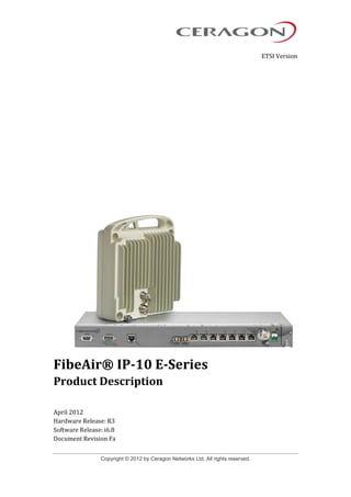
  • 1. Copyright © 2012 by Ceragon Networks Ltd. All rights reserved. ETSI Version FibeAir® IP-10 E-Series Product Description April 2012 Hardware Release: R3 Software Release: i6.8 Document Revision Fa
  • 2. FibeAir® IP-10 E-Series Product Description Ceragon Proprietary and Confidential Page 2 of 167 Notice This document contains information that is proprietary to Ceragon Networks Ltd. No part of this publication may be reproduced, modified, or distributed without prior written authorization of Ceragon Networks Ltd. This document is provided as is, without warranty of any kind. Registered Trademarks Ceragon Networks® is a registered trademark of Ceragon Networks Ltd. FibeAir® is a registered trademark of Ceragon Networks Ltd. CeraView® is a registered trademark of Ceragon Networks Ltd. Other names mentioned in this publication are owned by their respective holders. Trademarks CeraMap™, PolyView™, EncryptAir™, ConfigAir™, CeraMon™, EtherAir™, and MicroWave Fiber™, are trademarks of Ceragon Networks Ltd. Other names mentioned in this publication are owned by their respective holders. Statement of Conditions The information contained in this document is subject to change without notice. Ceragon Networks Ltd. shall not be liable for errors contained herein or for incidental or consequential damage in connection with the furnishing, performance, or use of this document or equipment supplied with it. Open Source Statement The Product may use open source software, among them O/S software released under the GPL or GPL alike license ("GPL License"). Inasmuch that such software is being used, it is released under the GPL License, accordingly. Some software might have changed. The complete list of the software being used in this product including their respective license and the aforementioned public available changes is accessible on http://www.gnu.org/licenses/. Information to User Any changes or modifications of equipment not expressly approved by the manufacturer could void the user’s authority to operate the equipment and the warranty for such equipment.
  • 3. FibeAir® IP-10 E-Series Product Description Ceragon Proprietary and Confidential Page 3 of 167 Revision History Rev Date Author Description Approved by Date A November 8, 2011 Baruch Gitlin First revision for release 6.8. Tomer Carmeli November 8, 2011 B November 17, 2011 Baruch Gitlin Added waveguide flanges table for 1500HP/RFU-HP and revised 1500HP/RFU-HP transmit power specifications. Tomer Carmeli/Rami Lerner November 17, 2011 C November 27, 2011 Baruch Gitlin Added mechanical, environmental, and electrical specifications for RFUs and revised Protection Options section. Tomer Carmeli/Rami Lerner November 27, 2011 D February 8, 2012 Baruch Gitlin Revised RFU-C and 1500HP/RFU- HP specifications. Rami Lerner February 8, 2012 E March 15, 2012 Baruch Gitlin Revise PDV value for PTP optimized transport. Tomer Carmeli March 15, 2012 F April 2, 2012 Baruch Gitlin Revise RFU-C frequency specifications. Rami Lerner April 2, 2012
  • 4. FibeAir® IP-10 E-Series Product Description Ceragon Proprietary and Confidential Page 4 of 167 Table of Contents 1. About This Guide............................................................................................ 14 2. What You Should Know ................................................................................. 14 3. Target Audience ............................................................................................. 14 4. Related Documents........................................................................................ 14 5. Section Summary ........................................................................................... 15 6. Product Overview ........................................................................................... 16 6.1 IP-10E Highlights ......................................................................................................... 17 6.1.1 Best Utilization of Spectrum Assets ............................................................................. 17 6.1.2 Spectral Efficiency........................................................................................................ 17 6.1.3 Radio Link .................................................................................................................... 17 6.1.4 Wireless Network ......................................................................................................... 18 6.1.5 Scalability ..................................................................................................................... 18 6.1.6 Availability .................................................................................................................... 19 6.1.7 Network Level Optimization ......................................................................................... 19 6.1.8 Network Management .................................................................................................. 19 6.1.9 Power Saving Mode High Power Radio....................................................................... 20 6.2 Hardware Description................................................................................................... 21 6.2.1 Dimensions and Voltage Rating................................................................................... 21 6.2.2 Front Panel Interfaces.................................................................................................. 21 6.2.3 Available Assembly Options * ...................................................................................... 22 6.2.4 RFU Options................................................................................................................. 22 6.3 Licensing ...................................................................................................................... 23 6.3.1 Working with License Keys .......................................................................................... 23 6.3.2 Licensed Features........................................................................................................ 23 6.4 Radio Configuration Options........................................................................................ 25 6.5 Feature Overview......................................................................................................... 26 6.5.1 General Features ......................................................................................................... 26 6.5.2 Capacity-Related Features .......................................................................................... 26 6.5.3 Ethernet Features ........................................................................................................ 27 6.5.4 Synchronization Features ............................................................................................ 28 6.5.5 Security Features ......................................................................................................... 28 6.5.6 Management Features ................................................................................................. 29 7. Functional Description................................................................................... 31 7.1 Functional Overview..................................................................................................... 32 7.2 IDU Interfaces .............................................................................................................. 33 7.2.1 Ethernet Interfaces....................................................................................................... 33 7.2.2 Additional Interfaces..................................................................................................... 34 7.2.3 Power Options.............................................................................................................. 34 7.3 Nodal Configuration ..................................................................................................... 35 7.3.1 Nodal Configuration Benefits ....................................................................................... 35 7.3.2 IP-10E Nodal Design.................................................................................................... 35
  • 5. FibeAir® IP-10 E-Series Product Description Ceragon Proprietary and Confidential Page 5 of 167 7.3.3 Nodal Enclosure Design............................................................................................... 36 7.3.4 Nodal Management...................................................................................................... 37 7.3.5 Centralized System Features....................................................................................... 38 7.3.6 Ethernet Connectivity in Nodal Configurations ............................................................ 38 7.4 Protection Options........................................................................................................ 39 7.4.1 1+1 HSB Protection...................................................................................................... 39 7.4.2 2+0 Multi-Radio and 2+0 Multi-Radio with IDU and Line Protection............................ 41 7.4.3 2+2 HSB Protection...................................................................................................... 41 8. Main Features ................................................................................................. 43 8.1 Adaptive Coding and Modulation (ACM)...................................................................... 44 8.1.1 Eight Working Points.................................................................................................... 44 8.1.2 Hitless and Errorless Step-by-Step Adjustments......................................................... 45 8.1.3 Configurable Minimum ACM Profile............................................................................. 45 8.1.4 ACM Benefits ............................................................................................................... 45 8.1.5 ACM and Built-In Quality of Service............................................................................. 46 8.1.6 ACM with Adaptive Transmit Power ............................................................................ 46 8.2 Multi-Radio ................................................................................................................... 48 8.2.1 IDU and Line Protection in Multi-Radio........................................................................ 49 8.3 XPIC Support ............................................................................................................... 50 8.3.1 XPIC Benefits............................................................................................................... 50 8.3.2 XPIC Implementation ................................................................................................... 51 8.3.3 XPIC and Multi-Radio................................................................................................... 52 8.4 Space and Frequency Diversity ................................................................................... 53 8.4.1 Baseband Switching (BBS) Frequency Diversity......................................................... 54 8.4.2 Baseband Switching (BBS) Space Diversity................................................................ 54 8.4.3 IF Combining (IFC)....................................................................................................... 55 8.4.4 Diversity Type Comparison.......................................................................................... 55 8.5 LTE-Ready Latency ..................................................................................................... 56 8.5.1 Benefits of IP-10E’s Top-of-the-Line Low Latency....................................................... 56 8.6 Carrier Grade Ethernet................................................................................................. 57 8.6.1 Carrier Ethernet Services Based on IP-10E ................................................................ 58 8.6.2 Carrier Ethernet Services Based on IP-10E - Node Failure ........................................ 59 8.7 Ethernet Switching ....................................................................................................... 60 8.7.1 Smart Pipe Mode ......................................................................................................... 60 8.7.2 Managed Switch Mode................................................................................................. 61 8.7.3 Metro Switch Mode ...................................................................................................... 61 8.8 Integrated QoS Support ............................................................................................... 62 8.8.1 QoS Overview .............................................................................................................. 62 8.8.2 IP-10E Standard QoS .................................................................................................. 63 8.8.3 QoS Traffic Flow in Smart Pipe Mode.......................................................................... 63 8.8.4 QoS Traffic Flow in Managed Switch and Metro Switch Mode.................................... 64 8.8.5 Enhanced QoS............................................................................................................. 64 8.8.6 Weighted Random Early Detection.............................................................................. 65 8.8.7 Standard and Enhanced QoS Comparison.................................................................. 67 8.8.8 Enhanced QoS Benefits............................................................................................... 67 8.9 Spanning Tree Protocol (STP) Support ....................................................................... 68 8.9.1 RSTP ...................................................................................................................... 68
  • 6. FibeAir® IP-10 E-Series Product Description Ceragon Proprietary and Confidential Page 6 of 167 8.9.2 Carrier Ethernet Wireless Ring-Optimized RSTP ........................................................ 68 8.9.3 Ring-Optimized RSTP Limitations................................................................................ 69 8.9.4 Basic IP-10E Wireless Carrier Ethernet Ring Topology Examples.............................. 70 8.9.4.1 IP-10E Wireless Carrier Ethernet Ring with Dual-Homing .......................... 70 8.9.4.2 IP-10E Wireless Carrier Ethernet Ring - 1+0 .............................................. 71 8.9.4.3 IP-10E Wireless Carrier Ethernet Ring - Aggregation Site.......................... 71 8.10 Ethernet Line Protection............................................................................................... 72 8.10.1Multi-Unit LAG.............................................................................................................. 73 8.10.2Ethernet Line Protection Comparison .......................................................................... 73 8.11 Asymmetrical Scripts.................................................................................................... 74 8.12 Synchronization Support.............................................................................................. 76 8.12.1Wireless IP Synchronization Challenges ..................................................................... 76 8.12.2Precision Timing-Protocol (PTP).................................................................................. 77 8.12.3Synchronous Ethernet (SyncE).................................................................................... 77 8.12.4IP-10E Synchronization Solution ................................................................................. 78 8.12.5Synchronization Using Precision Timing Protocol (PTP) Optimized Transport ........... 79 8.12.6Native Sync Distribution Mode..................................................................................... 80 8.12.6.1 Native Sync Distribution Examples.............................................................. 81 8.12.7SyncE “Regenerator” Mode ......................................................................................... 83 9. RFU Descriptions ........................................................................................... 84 9.1 RFU Selection Guide ................................................................................................... 85 9.2 RFU-C .......................................................................................................................... 86 9.2.1 Main Features of RFU-C.............................................................................................. 86 9.2.2 RFU-C Frequency Bands............................................................................................. 87 9.2.3 RFU-C Mechanical, Electrical, and Environmental Specifications............................... 98 9.2.4 Mediation Device Losses ............................................................................................. 99 9.2.5 RFU-C Antenna Connection ........................................................................................ 99 9.2.6 RFU-C Waveguide Flanges ....................................................................................... 100 9.3 1500HP/RFU-HP........................................................................................................ 101 9.3.1 Main Features of 1500HP/RFU-HP ........................................................................... 101 9.3.2 1500HP/RFU-HP Frequency Bands .......................................................................... 102 9.3.3 1500HP/RFU-HP Mechanical, Electrical, and Environmental Specifications ............ 103 9.3.4 1500HP/RFU-HP Installation Types........................................................................... 104 9.3.5 1500HP/RFU-HP Supported Configurations.............................................................. 104 9.3.6 1500HP/RFU-HP All-Indoor Configurations............................................................... 105 9.3.7 Branching Networks ................................................................................................... 105 9.3.7.1 Split Mount Branching Loss....................................................................... 106 9.3.7.2 All-Indoor Branching Loss ......................................................................... 107 9.3.8 1500HP/RFU-HP Waveguide Flanges....................................................................... 108 9.4 RFH-HS...................................................................................................................... 109 9.4.1 Main Features of RFU-HS.......................................................................................... 109 9.4.2 RFU-HS Frequency Bands ........................................................................................ 110 9.4.3 RFU-HS Mechanical, Electrical, and Environmental Specifications .......................... 111 9.4.4 RFU-HS Antenna Types ............................................................................................ 112 9.4.5 RFU-HS Antenna Connection.................................................................................... 112 9.4.6 RFU-HS Mediation Device Losses............................................................................. 113
  • 7. FibeAir® IP-10 E-Series Product Description Ceragon Proprietary and Confidential Page 7 of 167 9.5 RFU-SP...................................................................................................................... 114 9.5.1 Main Features of RFU-SP.......................................................................................... 114 9.5.2 RFU-SP Frequency Bands......................................................................................... 114 9.5.3 RFU-SP Mechanical, Electrical, and Environmental Specifications .......................... 115 9.5.4 RFU-SP Direct Mount Installation .............................................................................. 116 9.5.5 RFU-SP Antenna Connection .................................................................................... 116 9.5.6 RFU-SP Mediation Device Losses............................................................................. 117 9.6 RFU-P ........................................................................................................................ 118 9.6.1 RFU-P Mechanical, Electrical, and Environmental Specifications............................. 118 9.6.2 RFU-P Mediation Device Losses ............................................................................... 118 10. Typical Configurations................................................................................. 119 10.1 Point to point configurations....................................................................................... 119 10.1.11+0 119 10.1.21+1 HSB120 10.1.32+0/XPIC Link, “no Multi-Radio” Mode ...................................................................... 120 10.1.42+0/XPIC Link, “Multi-Radio” Mode ........................................................................... 121 10.1.52+2/XPIC/Multi-Radio MW Link ................................................................................. 121 10.2 Nodal Configurations.................................................................................................. 122 10.2.1Chain with 1+0 Downlink and 1+1 HSB Uplink .......................................................... 122 10.2.2Node with 2 x 1+0 Downlinks and 1 x 1+1 HSB Uplink ............................................. 123 10.2.3Chain with 1+1 Downlink and 1+1 HSB Uplink .......................................................... 123 10.2.4Ring with 3 x 1+0 Links at Main Site .......................................................................... 124 10.2.5Ring with 3 x 1+1 HSB Links at Main Site.................................................................. 124 10.2.6Node with 1 x 1+1 HSB Downlink and 1 x 1+1 HSB Uplink....................................... 125 10.2.7Ring with 4 x 1+0 Links .............................................................................................. 125 10.2.8Ring with 3 x 1+0 Links + Spur Link 1+0.................................................................... 126 10.2.9Ring with 4 x 1+0 MW Links and 1 x Fiber Link (5 hops total)................................... 126 10.2.10Ring with 2 x 2+0/XPIC MW Links and 1 x Fiber Link (3 hops total) ....................... 127 11. Management and System Security.............................................................. 128 11.1 PolyView End-To-End Network Management System .............................................. 130 11.1.1PolyView Main Features ............................................................................................ 130 11.1.2PolyView User Interface............................................................................................. 131 11.1.3PolyView Security Features ....................................................................................... 131 11.1.4PolyView Advantages ................................................................................................ 132 11.1.5PolyView Server Components ................................................................................... 134 11.1.5.1 MySQL Database ...................................................................................... 134 11.1.5.2 FTP/ SFTP Server ..................................................................................... 134 11.1.5.3 XML & HTTP Proxy ................................................................................... 134 11.1.5.4 Server Redundancy................................................................................... 134 11.2 Web-Based Element Management System (Web EMS) ........................................... 135 11.3 CeraBuild ................................................................................................................... 136 11.4 System Security Features.......................................................................................... 137 11.4.1Ceragon’s Layered Security Concept ........................................................................ 137 11.4.2Defenses in management communication channels ................................................. 138 11.4.3Defenses in user and system authentication procedures .......................................... 139 11.4.4Monitoring tools.......................................................................................................... 139
  • 8. FibeAir® IP-10 E-Series Product Description Ceragon Proprietary and Confidential Page 8 of 167 11.4.5Secure communication channels ............................................................................... 140 11.4.5.1 HTTPS ....................................................................................................... 140 11.4.5.2 SNMP ........................................................................................................ 140 11.4.5.3 Server authentication (SSL / SLLv3) ......................................................... 140 11.4.5.4 Encryption.................................................................................................. 141 11.4.5.5 SSH............................................................................................................ 141 11.4.5.6 SFTP.......................................................................................................... 141 11.4.6Security log................................................................................................................. 141 11.5 End to End Multi-Layer OAM ..................................................................................... 143 11.5.1Configurable RSL Threshold Alarms and Traps ........................................................ 143 11.5.2Connectivity Fault Management (CFM) ..................................................................... 143 11.5.3Ethernet Statistics (RMON)........................................................................................ 144 11.5.3.1 Ingress Line Receive Statistics.................................................................. 144 11.5.3.2 Ingress Radio Transmit Statistics .............................................................. 145 11.5.3.3 Egress Radio Receive Statistics................................................................ 145 11.5.3.4 Egress Line Transmit Statistics ................................................................. 145 12. Specifications............................................................................................... 146 12.1 General Specifications ............................................................................................... 146 12.1.16-18 GHz146 12.1.223-38 GHz.................................................................................................................. 147 12.2 RFU Support .............................................................................................................. 148 12.3 Radio Capacity........................................................................................................... 149 12.3.13.5 MHz .................................................................................................................... 149 12.3.27 MHz .................................................................................................................... 149 12.3.314 MHz .................................................................................................................... 150 12.3.428 MHz .................................................................................................................... 150 12.3.540 MHz .................................................................................................................... 151 12.3.656 MHz .................................................................................................................... 151 12.3.7Transmit Power with RFU-C(dBm)............................................................................. 152 12.3.8Transmit Power with RFU-SP/HS/HP (dBm).............................................................. 152 12.3.9Transmit Power with RFU-P (dBm)............................................................................ 153 12.3.10Receiver Threshold (RSL) with RFU-C (dBm @ BER = 10-6)................................. 154 12.3.11Receiver Threshold (RSL) with RFU-SP/HS/HP/1500HP (dBm @ BER = 10-6) .... 156 12.3.12Receiver Threshold (RSL) with RFU-P (dBm @ BER = 10-6)................................. 158 12.4 Ethernet Latency Specifications................................................................................. 160 12.4.1Latency – 3.5MHz Channel Bandwidth...................................................................... 160 12.4.2Latency – 7MHz Channel Bandwidth......................................................................... 160 12.4.3Latency – 14MHz Channel Bandwidth....................................................................... 161 12.4.4Latency – 28MHz Channel Bandwidth....................................................................... 161 12.4.5Latency – 40MHz Channel Bandwidth....................................................................... 162 12.4.6Latency – 56MHz Channel Bandwidth....................................................................... 162 12.5 Interface Specifications.............................................................................................. 163 12.5.1Ethernet Interface Specifications ............................................................................... 163 12.5.2Carrier Ethernet Functionality .................................................................................... 163 12.6 Network Management, Diagnostics, Status, and Alarms........................................... 165
  • 9. FibeAir® IP-10 E-Series Product Description Ceragon Proprietary and Confidential Page 9 of 167 12.7 Mechanical Specifications.......................................................................................... 165 12.8 Standard compliance ................................................................................................. 166 12.9 Environmental ............................................................................................................ 166 12.10 Power Input Specifications......................................................................................... 166 12.11 Power Consumption Specifications ........................................................................... 167 12.12 Power Consumption with RFU-HP in Power Saving Mode ....................................... 167
  • 10. FibeAir® IP-10 E-Series Product Description Ceragon Proprietary and Confidential Page 10 of 167 List of Figures IP-10E Front Panel and Interfaces ...................................................................... 21 IP-10E Front Panel with Dual Feed Power.......................................................... 21 Functional Block Diagram................................................................................... 31 FibeAir IP-10E Block Diagram............................................................................. 32 Main Nodal Enclosure.......................................................................................... 36 Extension Nodal Enclosure................................................................................. 36 Scalable Nodal Enclosure ................................................................................... 37 1+1 HSB Protection – Connecting the IDUs....................................................... 40 1+1 HSB Node with BBS Space Diversity........................................................... 40 3 x 1+1 Aggregation Site ..................................................................................... 41 2+2 with XPIC and Multi-Radio............................................................................ 42 Adaptive Coding and Modulation with Eight Working Points........................... 44 Adaptive Coding and Modulation ....................................................................... 45 IP-10E ACM with Adaptive Power Contrasted to Other ACM Implementations47 Typical 2+0 Multi-Radio Link Configuration....................................................... 48 Typical 2+2 Multi-Radio Terminal Configuration with HSB Protection............. 48 Dual Polarization.................................................................................................. 50 XPIC - Orthogonal Polarizations ......................................................................... 51 XPIC – Impact of Misalignments and Channel Degradation ............................. 51 XPIC – Impact of Misalignments and Channel Degradation ............................. 52 Direct and Reflected Signals............................................................................... 53 Diversity Signal Flow........................................................................................... 54 Carrier Grade Ethernet Feature Summary.......................................................... 57 Carrier Ethernet Services Based on IP-10E ....................................................... 58 Carrier Ethernet Services Based on IP-10E - Node Failure............................... 59 Carrier Ethernet Services Based on IP-10E - Node Failure (continued)........... 59 Ethernet Switching............................................................................................... 60 Smart Pipe Mode QoS Traffic Flow..................................................................... 63 Managed Switch and Metro Switch QoS Traffic Flow........................................ 64
  • 11. FibeAir® IP-10 E-Series Product Description Ceragon Proprietary and Confidential Page 11 of 167 IP-10E Enhanced QoS.......................................................................................... 65 Synchronized Packet Loss.................................................................................. 66 Random Packet Loss with Increased Capacity Utilization Using WRED ......... 66 Ring-Optimized RSTP Solution........................................................................... 69 Basic IP-10E Wireless Carrier Ethernet Ring ..................................................... 70 IP-10E Wireless Carrier Ethernet Ring with Dual-Homing................................. 70 IP-10E Wireless Carrier Ethernet Ring - 1+0 ...................................................... 71 IP-10E Wireless Carrier Ethernet Ring - Aggregation Site ................................ 71 Hardware Protection with Single Interface Using Optical Splitter.................... 72 Full protection with Dual Interface Using Optical Splitters and LAG ............... 72 Full Protection Using Multi-Unit LAG ................................................................. 72 Symmetrical Chain Example ............................................................................... 74 Asymmetrical Chain Example ............................................................................. 74 Symmetrical Aggregation Site Example............................................................. 75 Asymmetrical Aggregation Site Example........................................................... 75 Precision Timing Protocol (PTP) Synchronization ............................................ 77 Synchronous Ethernet (SyncE)........................................................................... 78 PTP Optimized Transport .................................................................................... 79 Native Sync Distribution Mode ........................................................................... 80 Native Sync Distribution Mode Usage Example ................................................ 81 Native Sync Distribution Mode – Tree Scenario ................................................ 82 Native Sync Distribution Mode – Ring Scenario (Normal Operation)............... 82 Native Sync Distribution Mode – Ring Scenario (Link Failure)......................... 83 RFU-C – Waveguide Flanges............................................................................. 100 All-Indoor Vertical Branching............................................................................ 106 Split Mount Branching and All-Indoor Compact.............................................. 106 FibeAir IP-10E Typical Configurations – 1+0 ................................................... 119 FibeAir IP-10E Typical Configurations 1+1 HSB.............................................. 120 2+0/XPIC Link, “no Multi-Radio” Mode............................................................. 120 2+0/XPIC Link, “Multi-Radio” Mode .................................................................. 121
  • 12. FibeAir® IP-10 E-Series Product Description Ceragon Proprietary and Confidential Page 12 of 167 2+2/XPIC/Multi-Radio MW Link.......................................................................... 121 Chain with 1+0 Downlink and 1+1 HSB Uplink................................................. 122 Node with 2 x 1+0 Downlinks and 1 x 1+1 HSB Uplink.................................... 123 Chain with 1+1 Downlink and 1+1 HSB Uplink................................................. 123 Ring with 3 x 1+0 Links at Main Site................................................................. 124 Ring with 3 x 1+1 HSB Links at Main Site......................................................... 124 Node with 1 x 1+1 HSB Downlink and 1 x 1+1 HSB Uplink ............................. 125 Ring with 4 x 1+0 Links...................................................................................... 125 Ring with 3 x 1+0 Links + Spur Link 1+0 .......................................................... 126 Ring with 4 x 1+0 MW Links and 1 x Fiber Link (5 hops total) ........................ 126 Ring with 2 x 2+0/XPIC MW Links and 1 x Fiber Link (3 hops total)............... 127 Integrated IP-10E Management Tools............................................................... 129 Security Solution Architecture Concept........................................................... 137 OAM Functionality ............................................................................................. 143
  • 13. FibeAir® IP-10 E-Series Product Description Ceragon Proprietary and Confidential Page 13 of 167 List of Tables Section Summary................................................................................................. 15 Intelligent Ethernet Header Compression.......................................................... 27 Ethernet Interface Functionality.......................................................................... 33 Comparison of IP-10E Protection Options ......................................................... 39 ACM Working Points (Profiles) ........................................................................... 44 BBS and IFC Comparison.................................................................................... 55 Managed Switch Mode......................................................................................... 61 Metro Switch Mode .............................................................................................. 61 IP-10E Standard and Enhanced QoS Features .................................................. 67 Ethernet Line Protection Comparison................................................................ 73 RFU Selection Guide............................................................................................ 85 RFU-C Mechanical, Electrical, and Environmental Specifications ................... 98 RFU-C Mediation Device Losses......................................................................... 99 1500HP/RFU-HP Mechanical, Electrical, and Environmental Specifications . 103 1500HP/RFU-HP – Waveguide Flanges............................................................. 108 RFU-HS Mechanical, Electrical, and Environmental Specifications............... 111 RFU-SP Frequency Bands................................................................................. 114 RFU-SP Mechanical, Electrical, and Environmental Specifications ............... 115 RFU-HS-SP Antennas ........................................................................................ 116 RFU-P Mechanical, Electrical, and Environmental Specifications ................. 118 RFU-P Mediation Device Losses....................................................................... 118
  • 14. FibeAir® IP-10 E-Series Product Description Ceragon Proprietary and Confidential Page 14 of 167 1. About This Guide This document describes the main features, components, and specifications of the FibeAir IP-10 E-Series high capacity IP network solution. This document also describes a number of typical FibeAir IP-10E configuration options. This document applies to hardware version R3 and software version I6.8. 2. What You Should Know This document describes applicable ETSI standards and specifications. A North America version of this document (ANSI, FCC) is also available. 3. Target Audience This manual is intended for use by Ceragon customers, potential customers, and business partners. The purpose of this manual is to provide basic information about the FibeAir IP-10E for use in system planning, and determining which FibeAir IP-10E configuration is best suited for a specific network. 4. Related Documents  FibeAir IP-10 System Installation Guide - DOC-00023199  FibeAir IP-10 License Management System - DOC-00019183  FibeAir IP-10 Web Based Management User Guide, DOC-00018688  PolyView User Guide – DOC-00008492  FibeAir CeraBuild Commission Reports Guide, DOC-00028133  FibeAir RFU-HP Product Description  FibeAir RFU-HP Installation Guide - DOC-00015514  FibeAir RFU-C Product Description  FibeAir RFU-C Installation Guide - DOC-00017708  FibeAir RFU-HS Product Description  FibeAir RFU-HS Installation Guide - DOC-00022617  FibeAir RFU-SP Product Description  FibeAir RFU-SP Installation Guide - DOC-00015515  RFU-P Installation Guide - DOC-00015520
  • 15. FibeAir® IP-10 E-Series Product Description Ceragon Proprietary and Confidential Page 15 of 167 5. Section Summary This Product Description includes the following sections: Section Summary Section Summary of Contents Product Overview Provides an overview of the FibeAir IP-10E, including basic information about IP-10E and its features, a description of some common applications in which IP-10E is used, a description of IP-10E’s hardware and interfaces, and an explanation of the licensing process for certain IP-10E features. Functional Description Includes a functional block diagram of IP-10E, and describes IP-10E’s main components and interfaces, including detailed descriptions of IP-10E’s nodal configuration option, and protected configuration options. Main Features Provides detailed descriptions of IP-10E’s main features. RFU Descriptions Describes the Radio Frequency Units (RFU) that can be used in an IP-10E system, including basic specifications and an RFU comparison chart. Typical Configurations Provides diagrams of several typical IP-10E configurations. Management and System Security Provides an overview of the Ceragon applications used to manage an IP-10E system, including the PolyView™ Network Management System (NMS), the Web-Based Element Management System (Web EMS), and the CeraBuild™ maintenance and provisioning application, and describes IP-10E’s system security features and end to end multi-layer OAM functionality. Specifications Lists the IP-10E specifications, including general specifications, radio capacity, interface, power, mechanical, and other specifications.
  • 16. FibeAir® IP-10 E-Series Product Description Ceragon Proprietary and Confidential Page 16 of 167 6. Product Overview FibeAir IP-10E is a high capacity carrier-grade wireless Ethernet backhaul product. FibeAir IP-10E features a powerful, integrated Ethernet switch for advanced networking functionality. With advanced service management and Operation Administration & Maintenance (OA&M) tools, the IP-10E solution simplifies network design, reduces CAPEX and OPEX, and improves overall network availability and reliability to support services with stringent SLA. FibeAir IP-10E covers the entire licensed frequency spectrum and offers a wide capacity range, from 10 Mbps to 1 Gbps over a single radio carrier, using a single Radio Frequency Unit (RFU), depending on traffic scenario based on payload and header compression. Additional functionality and capacity are enabled via license keys while using the same hardware. By enabling more capacity, at lower latencies to any location, with proper traffic management mechanisms and an optional downstream boost, FibeAir IP-10E is built to enhance end user Quality of Experience. Highlights of FibeAir IP-10E include:  Best utilization of spectrum assets  Reduced number of network elements  Improved network uptime  Future proof  Risk-free solution
  • 17. FibeAir® IP-10 E-Series Product Description Ceragon Proprietary and Confidential Page 17 of 167 6.1 IP-10E Highlights The following are just some of the highlights of IP-10E. 6.1.1 Best Utilization of Spectrum Assets IP-10E provides efficiencies at three levels -- spectral efficiency, radio link, and wireless network. By combining superior radio performance, advanced compression, and an end-to-end holistic approach for capacity, operators can effectively provides up to five times more traffic to their users. In other words, IP-10E enables more revenue generating subscribers in a given RAN. 6.1.2 Spectral Efficiency IP-10E provides unrivaled spectral efficiency in a given spectrum channel by optimizing capacity of a link using adaptive coding and modulation techniques. In addition, IP-10E’s intelligent Ethernet and payload compression mechanisms improves effective Ethernet throughput by up to 5 fold without affecting user traffic. 6.1.3 Radio Link  Latency – IP-10E boasts ultra-low latency features that are essential for 3G and LTE deployments. With low latency, IP-10E enables links to cascade further away from the fiber PoP, allowing wider coverage in a given network cluster. Ultra-low latency also translates into longer radio chains, broader radio rings, and shorter recovery times. Moreover, maintaining low packet delay variation ensures proper synchronization propagation across the network. Spectural Efficiency •Modulation •Header Compression Radio Link •Latency •System Gain •Power Adaptive ACM Wireless Network •QoS Mechanism •Resiliency (ABR, etc.) •OA&M Tools
  • 18. FibeAir® IP-10 E-Series Product Description Ceragon Proprietary and Confidential Page 18 of 167  System Gain – IP-10E’s unrivalled system gain provides higher link availability, smaller antennas, and longer link spans. IP-10E provides higher overall capacity while maintaining critical and real-time traffic saving both on operational and capital expenditures by using smaller antennas for given link budget.  Power Adaptive ACM – IP-10E sets the industry standard for Advanced Adaptive Code and Modulation (ACM), increasing network capacity over an existing infrastructure while reducing sensitivity to environmental interferences. In addition, IP-10E provides a unique technological combination of ACM with Adaptive Power to ensure high availability and unmatched link utilization. IP-10E’s ACM implementation includes an option to set a minimum modulation profile below which the system may not step down. 6.1.4 Wireless Network  Enhanced QoS – IP-10E enables operators to deploy differentiated services with stringent service level agreements while maximizing the utilization of network resources. IP-10E enables granular CoS classification and traffic management, network utilization monitoring, and support of EIR traffic without affecting CIR traffic. Enhanced QoS enables traffic shaping per queue and port in order to limit and control packet bursts, and improves the utilization of TCP flows using WRED protocols.  OA&M – With advanced service management and Operation Administration & Maintenance (OA&M) tools, IP-10E simplifies network design, reduces operational and capital expenditures, and improves overall network availability and reliability to support services with stringent SLA. 6.1.5 Scalability FibeAir IP-10E is a scalable solution that is based on a common hardware that supports any channel size, modulation scheme, capacity, network topology, and configuration. Scalability and hardware efficiency simplify logistics and allow for commonality of spare parts. A common hardware platform enables customers to upgrade the feature set as the need arises - Pay As You Grow - without requiring hardware replacement.
  • 19. FibeAir® IP-10 E-Series Product Description Ceragon Proprietary and Confidential Page 19 of 167 6.1.6 Availability  MTBF.– FibeAir IP-10E provides an unrivaled reliability benchmark, with radio MTBF exceeding 112 years, and average annual return rate around 1%. Ceragon radios are designed in-house and employ cutting-edge technology with unmatched production yield, and a mature installed-base exceeding 100,000 radios. In addition, advanced radio features such as multi-radio and cross polarization achieves 100% utilization of radio resources by load balancing based on instantaneous capacity per carrier. Important resulting advantages are reduction in capital expenditures due to less spare parts required for roll-out, and reduction in operating expenditures, as maintenance and troubleshooting occurrence is infrequent.  ACM – Adaptive Modulation has a remarkable synergy with FibeAir IP-10E’s built-in Layer 2 Quality of Service mechanism. Since QoS provides priority support for different classes of service, according to a wide range of criteria, it is possible to configure the system to discard only low priority packets as conditions deteriorate. Adaptive Power and Adaptive Coding & Modulation provides maximum availability and spectral efficiency in any deployment scenario. 6.1.7 Network Level Optimization FibeAir IP-10E optimizes overall network performance, scalability, resilience, and survivability by using hot-standby (HSB) configuration with no single point of failure. In addition, ring and mesh deployments increase resiliency with standard xSTP as well as with a proprietary enhancement to the industry standard RSTP, resulting in faster recovery time. FibeAir IP-10E helps create a more robust network, with minimum downtime and maximum service grade, ensuring better user experience, better immunity to failures, lower churn, and reduced expenditures. 6.1.8 Network Management Each IP-10 Network Element includes an HTTP web-based element manager (CeraWeb) that enables the operator to perform element configuration, RF, Ethernet, and PDH performance monitoring, remote diagnostics, alarm reports, and more. In addition, FibeAir IP-10E provides an SNMP-based northbound interface. Ceragon’s network management system, PolyView, offers best-in-class end-to- end Ethernet service management, network monitoring, and NMS survivability by using advanced OAM. PolyView, Ceragon’s network management solution, provides simplified network provisioning, configuration error prevention, monitoring, and troubleshooting tools that ensure better user experience, minimal network downtime and reduced expenditures on network level maintenance.
  • 20. FibeAir® IP-10 E-Series Product Description Ceragon Proprietary and Confidential Page 20 of 167 6.1.9 Power Saving Mode High Power Radio FibeAir IP-10E offers an optional ultra-high power radio solution that transmits the highest power in the industry, while employing an innovative Power Saving Mode that saves up to 30% power consumption. Power Saving Mode enables the deployment of smaller antennas, and reduces the need for repeater stations. Moreover, installation labor cost and electricity consumption are reduced, achieving an overall diminished carbon footprint.
  • 21. FibeAir® IP-10 E-Series Product Description Ceragon Proprietary and Confidential Page 21 of 167 6.2 Hardware Description FibeAir IP-10E features split-mount architecture consisting of an indoor unit (IDU) and a Radio Frequency Unit (RFU). For more information on RFU options, refer to RFU Descriptions on page 84. 6.2.1 Dimensions and Voltage Rating This section sets forth basic system specifications. For a more extensive description of IP-10E’s specifications, refer to Mechanical Specifications on page 165and Power Input Specifications on page 166.  Dimensions Height: 42.6 mm (1RU) Width: 439 mm Depth: 188 mm (fits in ETSI rack)  DC input voltage nominal rating: -48V 6.2.2 Front Panel Interfaces This section describes the IP-10E’s main interfaces. For a fuller description of the IP-10E’s interfaces, refer to IDU Interfaces on page 33. IP-10E Front Panel and Interfaces IP-10E Front Panel with Dual Feed Power
  • 22. FibeAir® IP-10 E-Series Product Description Ceragon Proprietary and Confidential Page 22 of 167 Main Interfaces:  5 x 10/100Base-T  2 x GbE combo ports: 10/100/1000Base-T or SFP 1000Base-X  RFU interface: N-type connector Additional Interfaces:  Terminal console  External alarms (4 inputs & 1 output)  PROT: Ethernet protection control interface (for 1+1 HSB mode support) In addition, each of the FE interfaces can be configured to support an alternate mode of operation:  MGT: Ethernet out-of-band management (up to 3 interfaces)  WS: Ethernet wayside 6.2.3 Available Assembly Options *  With or without XPIC support  With or without dual-feed power option 6.2.4 RFU Options FibeAir IP-10E is based on the latest Ceragon technology, and can be installed together with any FibeAir RFU, including:  FibeAir 1500HP (FibeAir RFU-HP-1rx or FibeAir RFU-HP-2rx)  FibeAir 1500HS (FibeAir RFU-HS)  FibeAir 1500SP (FibeAir RFU-SP)  FibeAir 1500P (FibeAir RFU-P)  FibeAir RFU-C FibeAir RFUs support multiple capacities, frequencies, modulation schemes, and configurations for various network requirements. The RFUs operate in the frequency range of 6-42 GHz, and support capacities of from 10 Mbps to 500 Mbps. For more detailed information on the RFU options for your IP-10E system, refer to RFU Descriptions on page 84.
  • 23. FibeAir® IP-10 E-Series Product Description Ceragon Proprietary and Confidential Page 23 of 167 6.3 Licensing This section describes FibeAir IP-10E’s licensing structure. FibeAir IP-10E offers a pay-as-you-grow concept to reduce network costs. Future capacity growth and additional functionality is enabled with license keys and an innovative stackable nodal solution using the same hardware. Licenses are divided into two categories:  Per Radio – Each IDU (both sides of the link) require a license.  Per Configuration – Only one license is required for the system. A 1+1 configuration requires the same set of licenses for both the active and the protected IDU. In nodal configuration for licenses that are not per radio, licenses should be assigned to the main (bottom) IDU in the enclosure. 6.3.1 Working with License Keys Ceragon provides a web-based License Management System (LMS). The LMS enables authorized users to generate license keys, which are generated per IDU serial number. In order to upgrade a license, the license-key must be entered into the IP-10E, followed by a cold reset. When the system returns online following the reset, its license key is checked, enabling access to new capacities and/or features. For more detailed information, refer to FibeAir IP- 10 License Management System, DOC-00019183. 6.3.2 Licensed Features As your network expands and additional functionality is desired, license keys can be purchased for the following features: Adaptive Coding and Modulation (ACM) Enables the Adaptive Coding and Modulation (ACM) feature. An ACM license is required per radio. If additional IDUs are required for non-radio functionality, no license is required for these units. Refer to Adaptive Coding and Modulation (ACM) on page 44. L2 Switch Enables Managed Switch and Metro Switch. A license is required for any IDU that requires the use of two or more Ethernet ports. Refer to Ethernet Switching on page 60. Capacity Upgrade Enables you to increase your system’s radio capacity in gradual steps by upgrading your capacity license.
  • 24. FibeAir® IP-10 E-Series Product Description Ceragon Proprietary and Confidential Page 24 of 167 Network Resiliency Enables Ring RSTP for improving network resiliency. Only one Network Resiliency license is required for an east-west configuration. An L2 Switch license must also be purchased to enable this feature. Refer to Carrier Ethernet Wireless Ring-Optimized RSTP on page 68. Ethernet Synchronization Enables configuration of an external source as a clock source for synchronous Ethernet output. Without this license, only a local (internal) clock can be used for Ethernet synchronization. Every node that is part of the sync path requires one license for 1+0 configurations or two licenses for 1+1 configurations. Refer to Synchronization Support on page 76. Enhanced QoS Enables the Enhanced QoS feature, including:  WRED  Eight queues  Shaping per queue A license is required per radio. Refer to Enhanced QoS on page 64. Asymmetrical Scripts Enables the use of asymmetrical scripts. Refer to Asymmetrical Scripts on page 74.
  • 25. FibeAir® IP-10 E-Series Product Description Ceragon Proprietary and Confidential Page 25 of 167 6.4 Radio Configuration Options The following are some of the typical configurations supported by the FibeAir IP-10E.  1+0  1+1 HSB  1+1 Space Diversity (BBS)  1+1 Frequency Diversity (BBS)  2+0/4+0 XPIC – optional Multi-Radio - optional Line/IDU/switch protection - optional  2+2/4+4 HSB XPIC – optional Multi-Radio - optional For more details about these configuration options, refer to Typical Configurations on page 119.
  • 26. FibeAir® IP-10 E-Series Product Description Ceragon Proprietary and Confidential Page 26 of 167 6.5 Feature Overview This section provides an overview of FibeAir IP-10E’s features. The main features are described in more detail in Main Features on page 43. 6.5.1 General Features  Nodal Configuration – In addition to the standard standalone configuration, FibeAir IP-10E can be set up in a nodal configuration in which several IP-10E IDUs are stacked in a dedicated modular shelf and act as a single network element with multiple radio links. For more information, refer to Nodal Configuration on page 35.  Protection – FibeAir IP-10E offers a number of protection options in both nodal and standalone configurations. For more information, refer to Protection Options on page 39.  Latency – FibeAir IP-10E provides best-in-class latency for all channels. For more information, refer to LTE-Ready Latency on page 56.  Dual-Feed Power Connection – Assembly options include dual-feed power for increased protection against outages. For more information, refer to Power Options on page 34. 6.5.2 Capacity-Related Features  High Spectral Efficiency: Modulations – QPSK to 256 QAM Radio capacity (ETSI) – Up to 20/50/100/220/280/500 Mbps over 3.5/7/14/28/40/56 MHz channels All licensed bands – L6, U6, 7, 8, 10, 11, 13, 15, 18, 23, 26, 28, 32, 38, 42 GHz Highest scalability – From 10 Mbps to 500 Mbps, using the same hardware, including the same RFU.  Adaptive Coding and Modulation (ACM) – FibeAir IP-10E employs the most advanced ACM technique for maximization of spectrum utilization and capacity over any given bandwidth and changing environmental conditions. For more information, refer to Adaptive Coding and Modulation (ACM) on page 44. Note: ACM cannot be used together with BBS Frequency and Space Diversity.  Cross Polarization Interference Canceller (XPIC) – FibeAir IP-10E’s implementation of XPIC enables two radio carriers to use the same frequency with a polarity separation between them by adaptively subtracting from each carrier the interfering cross carrier at the proper phase and level, with the ability to detect both streams even under the worst levels of cross polar discrimination interference such as 10 dB. For more information, refer to XPIC Support on page 50.
  • 27. FibeAir® IP-10 E-Series Product Description Ceragon Proprietary and Confidential Page 27 of 167  Multi-Radio – IP-10E offers Multi-Radio in 2+0 configurations, with an option for IDU and line protection to ensure continued service with graceful degradation in the event of IDU failure. Multi-Radio can also be used in a fully protected 2+2 configuration. Multi-Radio enables two separate radio links to be shared by a single Ethernet port. This provides an Ethernet link over the radio with double capacity, while still behaving as a single Ethernet interface. For more information, refer to Multi-Radio on page 48.  Diversity –FibeAir IP-10E supports Frequency Diversity through Baseband Switching (BBS). IP-10E also supports Space Diversity through Baseband Switching (BBS) and IF combining (IFC). Diversity provides an added level of protection to negate the effects of multipath phenomenon by providing for signal diversity such that if one signal is impaired, the other signal can replace or compensate for the impaired signal. For more information, refer to Space and Frequency Diversity on page 53. Note: BBS Frequency and Space Diversity cannot be used together with ACM.  Intelligent Ethernet Header Compression (patent-pending) – Improves effective throughput by up to 45% without affecting user traffic. Intelligent Ethernet Header Compression Ethernet Packet Size (Bytes) Capacity Increase by Compression 64 45% 96 29% 128 22% 256 11% 512 5% 6.5.3 Ethernet Features  MEF-Certified Carry Grade Ethernet – FibeAir IP-10E is fully MEF-9 and MEF-14 certified for all Carrier Ethernet services (E-Line and E-LAN). For more information, refer to Carrier Grade Ethernet on page 57.  Enhanced Ethernet Switching – FibeAir IP-10E supports three modes for Ethernet switching: Smart Pipe – Ethernet switching functionality is disabled and only a single Ethernet interface is enabled for user traffic. The unit effectively operates as a point-to-point Ethernet microwave radio. Managed Switch – Ethernet switching functionality is enabled based on VLANs. Metro Switch – Ethernet switching functionality is enabled based on an S-VLAN-aware bridge. For more information about Ethernet switching in FibeAir IP-10E, refer to Ethernet Switching on page 60.
  • 28. FibeAir® IP-10 E-Series Product Description Ceragon Proprietary and Confidential Page 28 of 167  Integrated QoS Support – FibeAir IP-10E offers integrated QoS functionality in all switching modes. In addition to its standard QoS functionality, IP-10E offers an enhanced QoS feature that includes eight queues instead of four, enhanced classification criteria, and WRED for congestion management. For more information, refer to Integrated QoS Support on page 62.  Spanning Tree Protocol – FibeAir IP-10E supports Rapid Spanning Tree Protocol (RSTP) to ensure a loop-free topology for any bridged LAN. IP- 10E also includes a proprietary implementation of RSTP that is optimized for ring topologies. For more information, refer to Spanning Tree Protocol (STP) Support on page 68.  Ethernet Line Protection – Multi-Unit LAG provides line protection for both the optical and electrical GbE interfaces in Smart Pipe mode. Multi- Unit LAG can be used in all of IP-10E’s HSB protection and diversity configurations. In Managed Switch and Metro Switch modes, GbE line protection can be provided for Fast Ethernet and optical GbE ports by using optical splitters. For more information, refer to Ethernet Line Protection on page 72. 6.5.4 Synchronization Features  Combinations of the following techniques can be used: PTP optimized transport Native sync distribution for nodal configurations, with SSM message support for path protection in ring topologies “SyncE regenerator" mode for pipe configurations For more information about IP-10E synchronization, refer to Synchronization Support on page 76. 6.5.5 Security Features  Timeout – FibeAir IP-10E includes a configurable inactivity time-out for closing management channels.  Password Security – FibeAir IP-10E enforces password strength and aging rules.  User Suspension and Expiration – Users can be suspended after a configurable number of unsuccessful login attempts and to expire at a certain, configurable date.  SSH Support – FibeAir IP-10E supports SHHv1 and SSHv2.  HTTPS Support – FibeAir IP-10E can be managed using HTTPS protocol.  Secure FTP (SFTP) – FibeAir IP-10E supports SFTP for certain management operations, such as uploading and downloading configuration files and downloading software updates. For more information about IP-10E security features, refer to System Security Features on page 137.
  • 29. FibeAir® IP-10 E-Series Product Description Ceragon Proprietary and Confidential Page 29 of 167 6.5.6 Management Features  Network Management System (NMS) – PolyView provides management functions for FibeAir IP-10E at the network level, as well as at the individual network element level. Using PolyView, you can perform the following for Ceragon elements in the network: Performance Reporting Inventory Reporting Software Download Configuration Management Trail Management View Current Alarms (with alarm synchronization) View an Alarm Log Create Alarm Triggers For more information about PolyView, refer to PolyView End-To-End Network Management System on page 130.  Web-Based Element Management –FibeAir IP-10 web-based element management is used to perform configuration operations and obtain statistical and performance information related to the system. For more information, refer to Web-Based Element Management System (Web EMS) on page 130.  Extensive Radio Capacity/Utilization Statistics: Statistics are collected at 15-minute and 24-hour intervals. Historical statistics are stored and made available when needed. Capacity/ACM statistics include: Maximum modulation in interval Minimum modulation in interval Number of seconds in an interval, during which active modulation was below the user-configured threshold Utilization statistics include: Maximal radio link utilization in an interval Average radio link utilization in an interval Number of seconds in an interval, during which radio link utilization was above the user-configured threshold  SNMP Support – FibeAir IP-10E supports SNMPv1, SNMPV2c, and SNMPv3.  RMON Support for Ethernet Statistics – FibeAir IP-10E supports RMON Ethernet statistic counters. For more information, refer to Ethernet Statistics (RMON) on page 144.
  • 30. FibeAir® IP-10 E-Series Product Description Ceragon Proprietary and Confidential Page 30 of 167  LLDP Support – FibeAir IP-10E supports the Link Layer Discovery Protocol (LLDP), a vendor-neutral layer 2 protocol that can be used by a station attached to a specific LAN segment to advertise its identity and capabilities and to receive identity and capacity information from physically adjacent layer 2 peers. LLDP significantly enhances PolyView’s auto-discovery capabilities. For more information, refer to PolyView Main Features on page 130.  In-Band Management – FibeAir IP-10E can optionally be managed in- band, via its radio and Ethernet interfaces. This method of management eliminates the need for a dedicated interface and network. In-band management uses a dedicated management VLAN, which is user- configurable.  Operations Administration and Maintenance (OAM) – FibeAir IP-10E supports complete OAM functionality at multiple layers, including: Alarms and events Maintenance signaling, including LOS and AIS Performance monitoring Maintenance commands, such as Loopbacks and APS commands For more information about OAM in IP-10E, refer to End to End Multi-Layer OAM on page 143.  Configurable RSL Alarms and Traps – Software Release i6.8 introduces a user-configurable RSL threshold. If the RSL falls beneath this threshold for at least five seconds, the system generates an alarm and trap. For more information, refer to Configurable RSL Threshold Alarms and Traps on page 143.  Ethernet Connectivity Fault Management (CFM) – FibeAir IP-10E utilizes IEEE 802.1ag CFM protocols to maintain smooth system operation and non-stop data flow. For more information, refer to Connectivity Fault Management (CFM) on page 143.
  • 31. FibeAir® IP-10 E-Series Product Description Ceragon Proprietary and Confidential Page 31 of 167 7. Functional Description Featuring an advanced architecture, FibeAir IP-10E uniquely integrates the latest radio technology with Ethernet networking. The FibeAir IP-10E radio core engine is designed to support native Ethernet over the air interface enhanced with Adaptive Power and Adaptive Coding & Modulation (ACM) for maximum spectral efficiency in any deployment scenario. The modular design is easily scalable with the addition of units or license keys. IP-10E supports the following modes for Ethernet switching:  Smart Pipe – Ethernet interface is enabled for user traffic. The unit effectively operates as a point-to-point Ethernet microwave radio.  Managed Switch – Ethernet switching functionality is enabled based on VLANs.  Metro Switch – Ethernet switching functionality is enabled based on an S- VLAN-aware bridge. For more information on IP-10E’s switching options, refer to Ethernet Switching on page 60. Functional Block Diagram
  • 32. FibeAir® IP-10 E-Series Product Description Ceragon Proprietary and Confidential Page 32 of 167 7.1 Functional Overview IP-10E can be installed in a standalone or a nodal configuration. The nodal configuration adds a backplane, which is required for certain functionality such as the XPIC, and which enables unified management of the system as a single network element with multiple radio links. For more information on the nodal configuration option and its benefits, refer to Nodal Configuration on page 35. FibeAir IP-10E Block Diagram The CPU acts as the IDU’s central controller, and all management frames received from or sent to external management applications must pass through the CPU. In a nodal configuration, the main unit’s CPU serves as the central controller for the entire node. The Mux assembles the radio frames, and holds the logic for protection, as well as Frequency and Space Diversity. The modem represents the physical layer, modulating, transmitting, and receiving the data stream.
  • 33. FibeAir® IP-10 E-Series Product Description Ceragon Proprietary and Confidential Page 33 of 167 7.2 IDU Interfaces This section describes in detail the IP-10E’s interfaces, including optional interface options. 7.2.1 Ethernet Interfaces FibeAir IP-10E contains two GbE Ethernet interfaces and six FE interfaces on the front panel. For the GbE interfaces, you can choose between two optical and two electrical physical interfaces. Both pairs of GbE interfaces are labeled Eth1 and Eth2. The optical interfaces are located to the left of the electrical interfaces. The remaining Ethernet interfaces (Eth3 through Eth7) are FE ports. All except Eth3 are dual function interfaces. They can be configured as traffic ports or functional ports for wayside or management, as shown in the following table. Eth8 is the radio interface. Ethernet Interface Functionality Interface Name Interface Rate Functionality Smart Pipe Carrier Ethernet Switching Protection FE 10/100 External protection/disabled External protection/disabled Eth1 Electrical GbE 10/100/1000 OR Optical GbE – 1000 Disabled/Traffic Disabled/Traffic Eth2 Electrical GbE 10/100/1000 OR Optical GbE – 1000 Disabled Disabled/Traffic Eth3 FE 10/100 Disabled/Traffic Disabled/Traffic Eth4 FE 10/100 Disabled/Wayside Disabled/Traffic/Wayside Eth5 FE 10/100 Disabled/Management Disabled/Traffic/Management Eth6 FE 10/100 Disabled/Management Disabled/Traffic/Management Eth7 FE 10/100 Disabled/Management Disabled/Traffic/Management Eth8 (Radio –N-type) According to Radio script Disabled/Traffic Disabled/Traffic IP-10E also includes an FE protection interface (RJ-45) for external protection. The protection interface is located towards the left side of the front panel, and is for use in standalone configurations. In Smart Pipe mode, only a single Ethernet interface can be used. Options are:  Eth1: Electrical GbE or Optical GbE  Eth 3: Electrical FE
  • 34. FibeAir® IP-10 E-Series Product Description Ceragon Proprietary and Confidential Page 34 of 167 7.2.2 Additional Interfaces  Terminal Console – A local craft terminal can be connected to the terminal console for local CLI management of the individual IDU. If the IDU is the main unit, access to other units in the configuration is also available through the Terminal Console.  External Alarms – IP-10E supports five external alarms, located towards the left of the front panel. There are five inputs, with configurable triggers, alarm texts, and alarm severity, and one output.  Backplane Connector – IP-10E has an extra connector on the back panel for connection to the backplane used in nodal configurations. Refer to Nodal Configuration on page 35. 7.2.3 Power Options IP-10E has a DC input voltage nominal rating of -48V. Some hardware versions include a dual-feed power connection for increased protection. In dual power units, the system will indicate whether received voltage in each connection is above or below the threshold power of approximately 40.5V, as follows:  The LED (and its WEB representation) will only be on if the voltage is above the threshold.  An alarm is raised if voltage is below the threshold.
  • 35. FibeAir® IP-10 E-Series Product Description Ceragon Proprietary and Confidential Page 35 of 167 7.3 Nodal Configuration IP-10E can be used in two distinct modes of operation:  Standalone configuration – Each IP-10E IDU is managed individually.  Nodal configuration – Up to six IP-10E IDUs are stacked in a dedicated modular shelf, and act as a single network element with multiple radio links. The following features are centralized in a nodal configuration:  Management  Ethernet Switching A nodal setup supports any combination of 1+0, 1+1, and 2+0/XPIC configurations. 7.3.1 Nodal Configuration Benefits The stackable nodal configuration offers many advantages. For new systems, the nodal configuration offers:  Low initial investment without compromising future growth potential  Risk-free deployment in light of unknown future growth patterns: Additional capacity Additional sites Additional redundancy For migration and replacement scenarios, the nodal configuration offers:  Optimized tail-site solution  Low initial footprint that can be increased gradually as legacy equipment is swapped 7.3.2 IP-10E Nodal Design Each IP-10E IDU in a nodal configuration operates as either the main unit or an extension unit. The IDU’s role is determined by its position in the nodal enclosure, with the lowest unit in the enclosure (Unit Number 1) always serving as the main unit. The main unit performs the following functions:  Provides a central controller for management  Provides radio and line interfaces Extension units provide radio and line interfaces, and are accessed through the main unit.
  • 36. FibeAir® IP-10 E-Series Product Description Ceragon Proprietary and Confidential Page 36 of 167 7.3.3 Nodal Enclosure Design Two types of shelves are available for a nodal configuration:  Main Nodal Enclosure – Each node must have a main nodal enclosure, which can hold two IP-10E IDUs.  Extension Nodal Enclosure –Up to two extension nodal enclosures can be stacked on top of the main nodal enclosure. Each extension nodal enclosure can contain two IP-10E IDUs. Main Nodal Enclosure Extension Nodal Enclosure Each nodal enclosure includes a backplane. The rear panel of an IP-10E IDU includes an extra connector for connection to the backplane. The following interfaces are implemented through the backplane:  Multi-Radio  Protection  XPIC IP-10E IDUs are hot-swappable, and additional extension nodal enclosures and IDUs can be added in the field as required, without affecting traffic.
  • 37. FibeAir® IP-10 E-Series Product Description Ceragon Proprietary and Confidential Page 37 of 167 Scalable Nodal Enclosure Using the stacking method, units in the bottom nodal enclosure act as main units, whereby a mandatory active main unit can be located in either of the two slots, and an optional standby main unit can be installed in the other slot. The switchover time is <50 msecs for all traffic-affecting functions. Units located in nodal enclosures other than the one on the bottom act as expansion units. Radios in each pair of units can be configured as either dual independent 1+0 links, or single fully-redundant 1+1 HSB links. 7.3.4 Nodal Management In a nodal configuration, all management is performed through the main unit. The main unit communicates with the extension units through the nodal backplane. The main unit’s CPU operates as the node’s central controller, and all management frames received from or sent to external management applications must pass through the CPU. A nodal configuration has a single IP management address, which is the address of the main unit. In a protected 1+1 configuration, the node has two IP addresses, those of each of the main units. The IP address of the active main unit is used to manage the node. Several methods can be used for IP-10E node management:  Local terminal CLI  CLI via telnet  Web-based management  SNMP
  • 38. FibeAir® IP-10 E-Series Product Description Ceragon Proprietary and Confidential Page 38 of 167 The PolyView NMS represents the node as a single unit. The Web-Based EMS enables access to all IDUs in the node from its main window. In addition, the management system provides access to other network equipment through in-band or out-of-band network management. To ease the reading and analysis of several IDU alarms and logs, the system time should be synchronized to the main unit’s time. 7.3.5 Centralized System Features The following IP-10E functions are configured centrally through the main unit in a nodal configuration:  IP Communications – All communication channels are opened through the main unit’s IP address.  User Management – Login, adding users, and deleting users are performed centrally.  Nodal Time Synchronization – System time is automatically synchronized for all IDUs in the node.  Nodal Software Version Management – Software can be upgraded or downgraded in all IDUs in the node from the main unit.  Nodal Configuration Backup – Configuration files can be created, downloaded, and uploaded from the main unit.  Nodal Reset – Extension units can be reset individually or collectively both from the main unit and locally. All other functions are performed for each IDU individually. 7.3.6 Ethernet Connectivity in Nodal Configurations Ethernet traffic in a nodal configuration is supported by interconnecting IDU switches with external cables. Traffic flow (dropping to local ports, sending to radio) is performed by the switches, in accordance with learning tables. Each IDU in the stack can be configured individually for Smart Pipe or Carrier Ethernet Switching modes. For more information about Ethernet switching, refer to Ethernet Switching on page 60.
  • 39. FibeAir® IP-10 E-Series Product Description Ceragon Proprietary and Confidential Page 39 of 167 7.4 Protection Options Equipment protection is possible in both standalone and nodal configurations. The following protected configurations are available:  1+1 HSB (with optional SD/FD using BBS)  2+0 Multi-Radio  2+0 Multi-Radio with IDU and Line Protection  2+2 HSB and Multi-Radio The following table summarizes the degree of protection provided by the various IP-10E configuration options: Comparison of IP-10E Protection Options Configuration # of IDUs per Terminal # of RFUs per Terminal Radio Capacity – Normal Radio Capacity – Unit Failure XPIC Support ACM Support BBS (SD/FD) Support 1+0 1 1 1 0 No Optional No 1+1 HSB 2 2 1 1 No Optional1 Optional 2+0 Multi-Radio 2 2 2 RFU Failure – 12 IDU (Slave) Failure – 13 IDU (Master) Failure - 0 Optional Optional No 2+0 Multi-Radio with IDU and Line Protection 2 2 2 RFU Failure – 14 IDU (Slave or Master) Failure - 15 Optional Optional6 No 2+2 HSB with Multi- Radio 4 4 2 2 Optional Optional No 7.4.1 1+1 HSB Protection A 1+1 configuration scheme can be used to provide full protection in the event of IDU or RFU failure. The two IDUs operate in active and standby mode. If there is a failure in the active IDU or RFU, the standby IDU and RFU pair switches to active mode. In a 1+1 configuration, the protection options are as follows:  Standalone – The IDUs must be connected by a dedicated Ethernet protection cable. Each IDU has a unique IP address.  Nodal – The IDUs are connected by the backplane of the nodal enclosure. There is one IP address for each of the main units. 1 ACM is not supported when BBS (SD/FD) is used. 2 With graceful degradation. 3 With graceful degradation. 4 With graceful degradation. 5 With graceful degradation. 6 ACM support is only provided for Ethernet traffic, not for TDM trails.
  • 40. FibeAir® IP-10 E-Series Product Description Ceragon Proprietary and Confidential Page 40 of 167 1+1 HSB can be used with BBS Space or Frequency Diversity. The following figure illustrates a 1+1 HSB configuration in a standalone setup, with an Ethernet protection cable connecting the two IDUs via their Protection ports. 1+1 HSB Protection – Connecting the IDUs The following figure illustrates a 1+1 HSB Space Diversity configuration in a standalone setup, with an Ethernet protection cable connecting the two IDUs via their Protection ports. 1+1 HSB Node with BBS Space Diversity The following figure shows an example of a 1+1 HSB nodal configuration used in an IP-10E 3 x 1+1 aggregation site. In this example, the node includes the following components:  One main nodal enclosure with two IDUs One configured as Main The other configured as Protected  One extension nodal enclosure with two IDUs configured as Extension  One extension nodal enclosure with one IDU configured as Extension
  • 41. FibeAir® IP-10 E-Series Product Description Ceragon Proprietary and Confidential Page 41 of 167 3 x 1+1 Aggregation Site 7.4.2 2+0 Multi-Radio and 2+0 Multi-Radio with IDU and Line Protection 2+0 Multi-Radio provides a significant degree of protection, in addition to doubling capacity by enabling two separate radio carriers to be shared by a single Ethernet port. In the event of RFU failure, or failure of the slave IDU, one RFU and IDU remain in operation, with graceful degradation of service to ensure that not all data is lost, but rather, a reduction of bandwidth occurs. However, if there is a failure of the master IDU, traffic and management access is lost. The IDU and line protection option eliminates this potential point of failure by providing for the standby IDU to assume the role of master IDU in the event of failure in the master IDU. Thus, Ethernet traffic is maintained with reduced bandwidth in the event of any single unit failure. Graceful degradation is provided with the help of IP-10E’s integrated QoS mechanism, which ensures that high-priority traffic is maintained in the event of reduced bandwidth. For further details about Multi-Radio, refer Multi-Radio on page 48. Note: A nodal enclosure is required for 2+0 Multi-Radio, both with and without IDU and line protection. 7.4.3 2+2 HSB Protection 2+2 HSB protection provides full redundancy between two pairs of IDUs. Each pair is a 2+0 link, which can be configured for XPIC or in different frequencies. If there is a failure in one of these pairs, the other pair takes over. A 2+2 protection scheme must be implemented by means of a nodal configuration. A 2+2 configuration consists of two pairs of IP-10E IDUs, each inserted in its own main nodal enclosure, with a protection cable to connect the main IDUs in each node. Protection is performed between the pairs. At any given time, one pair is active and the other is standby.
  • 42. FibeAir® IP-10 E-Series Product Description Ceragon Proprietary and Confidential Page 42 of 167 A 2+2 scheme is only possible between units in the main nodal enclosure. Extension nodal enclosures cannot be used in a 2+2 configuration. 2+2 protection can be used together with XPIC and/or Multi-Radio. The following figure illustrates a 2+2 configuration with both XPIC and Multi- Radio. The RFUs marked V are set to vertical polarization, while the RFUs marked H are set to horizontal polarization. 2+2 with XPIC and Multi-Radio
  • 43. FibeAir® IP-10 E-Series Product Description Ceragon Proprietary and Confidential Page 43 of 167 8. Main Features This section describes some of the most important IP-10E features, including:  Adaptive Coding and Modulation (ACM)  Multi-Radio  XPIC Support  Space and Frequency Diversity  LTE-Ready Latency  Carrier Grade Ethernet  Ethernet Switching  Integrated QoS Support  Spanning Tree Protocol (STP) Support  Ethernet Line Protection  Asymmetrical Scripts  Synchronization Support
  • 44. FibeAir® IP-10 E-Series Product Description Ceragon Proprietary and Confidential Page 44 of 167 8.1 Adaptive Coding and Modulation (ACM) FibeAir IP-10E employs full-range dynamic ACM. IP-10E’s ACM mechanism copes with 90 dB per second fading in order to ensure high transmission quality. IP-10E’s ACM mechanism is designed to work with IP-10E’s QoS mechanism to ensure that high priority voice and data packets are never dropped, thus maintaining even the most stringent service level agreements (SLAs). The hitless and errorless functionality of IP-10E’s ACM has another major advantage in that it ensures that TCP/IP sessions do not time-out. Without ACM, even interruptions as short as 50 milliseconds can lead to timeout of TCP/IP sessions, which are followed by a drastic throughout decrease while these sessions recover. Note: ACM cannot be used together with BBS Frequency and Space Diversity. It can be and often is used with Multi-Radio, but cannot be used with 2+0 Multi-Radio with IDU and line protection. 8.1.1 Eight Working Points IP-10E implements ACM with eight available working points, as follows: ACM Working Points (Profiles) Working Point (Profile) Modulation Profile 0 QPSK Profile 1 8 PSK Profile 2 16 QAM Profile 3 32 QAM Profile 4 64 QAM Profile 5 128 QAM Profile 6 256 QAM – Strong FEC Profile 7 256 QAM – Light FEC Adaptive Coding and Modulation with Eight Working Points
  • 45. FibeAir® IP-10 E-Series Product Description Ceragon Proprietary and Confidential Page 45 of 167 8.1.2 Hitless and Errorless Step-by-Step Adjustments ACM works as follows. Assuming a system configured for 128 QAM with ~170 Mbps capacity over a 28 MHz channel, when the receive signal Bit Error Ratio (BER) level reaches a predetermined threshold, the system preemptively switches to 64 QAM and the throughput is stepped down to ~140 Mbps. This is an errorless, virtually instantaneous switch. The system continues to operate at 64 QAM until the fading condition either intensifies or disappears. If the fade intensifies, another switch takes the system down to 32 QAM. If, on the other hand, the weather condition improves, the modulation is switched back to the next higher step (e.g., 128 QAM) and so on, step by step .The switching continues automatically and as quickly as needed, and can reach all the way down to QPSK during extreme conditions. Adaptive Coding and Modulation 8.1.3 Configurable Minimum ACM Profile When using ACM, the user can configure a minimum ACM profile. When a minimum ACM profile is configured, the system will not step down to any modulation below the minimum. For example, if the configured minimum ACM profile is 3 (32 QAM), stepping down below 32 QAM is not allowed. If the channel’s SNR degrades below the 32 QAM threshold, the radio will lose carrier synchronization, and will report loss of frame. 8.1.4 ACM Benefits The advantages of IP-10E’s dynamic ACM include:  Maximized spectrum usage  Increased capacity over a given bandwidth  Eight modulation/coding work points (~3 db system gain for each point change)  Hitless and errorless modulation/coding changes, based on signal quality 16 QAM QPSK 99.995 % 200 Unavailability Rx level Capacity (@ 28 MHz channel) 32 QAM 64 QAM 128 QAM 256 QAM 99.999 % 99.99 % 99.95 % 99.9 % Mbps170 200 140 100 200 120 200
  • 46. FibeAir® IP-10 E-Series Product Description Ceragon Proprietary and Confidential Page 46 of 167  Adaptive Radio Tx Power per modulation for maximal system gain per working point  An integrated QoS mechanism enables intelligent congestion management to ensure that high priority traffic is not affected during link fading 8.1.5 ACM and Built-In Quality of Service IP-10E’s ACM mechanism is designed to work with IP-10E’s QoS mechanism to ensure that high priority voice and data packets are never dropped, thus maintaining even the most stringent SLAs. Since QoS provides priority support for different classes of service, according to a wide range of criteria, you can configure IP-10E to discard only low priority packets as conditions deteriorate. For more information on IP-10E’s QoS and Enhanced QoS functionality, refer to Integrated QoS Support on page 61. If you want to rely on an external switch’s QoS, ACM can work with them via the flow control mechanism supported in the radio. 8.1.6 ACM with Adaptive Transmit Power When planning ACM-based radio links, the radio planner attempts to apply the lowest transmit power that will perform satisfactorily at the highest level of modulation. During fade conditions requiring a modulation drop, most radio systems cannot increase transmit power to compensate for the signal degradation, resulting in a deeper reduction in capacity. IP-10E is capable of adjusting power on the fly, and optimizing the available capacity at every modulation point, as illustrated in the figure below. This figure shows how operators that want to use ACM to benefit from high levels of modulation (e.g., 256 QAM) must settle for low system gain, in this case, 18 dB, for all the other modulations as well. With FibeAir IP-10E, operators can automatically adjust power levels, achieving the extra 4 dB system gain that is required to maintain optimal throughput levels under all conditions.
  • 47. FibeAir® IP-10 E-Series Product Description Ceragon Proprietary and Confidential Page 47 of 167 IP-10E ACM with Adaptive Power Contrasted to Other ACM Implementations
  • 48. FibeAir® IP-10 E-Series Product Description Ceragon Proprietary and Confidential Page 48 of 167 8.2 Multi-Radio Multi-Radio enables two separate radio carriers to be shared by a single Ethernet port. This provides an Ethernet link over the radio with double capacity, while still behaving as a single Ethernet interface. The IDUs in a Multi-Radio setup operate in master and slave mode. In Multi-Radio mode, traffic is divided among the two carriers optimally at the radio frame level without requiring Ethernet Link Aggregation, and is not dependent on the number of MAC addresses, the number of traffic flows, or momentary traffic capacity. During fading events which cause ACM modulation changes, each carrier fluctuates independently with hitless switchovers between modulations, increasing capacity over a given bandwidth and maximizing spectrum utilization. The result is 100% utilization of radio resources in which traffic load is balanced based on instantaneous radio capacity per carrier and is independent of data/application characteristics, such as the number of flows or capacity per flow. Typical 2+0 Multi-Radio Link Configuration Typical 2+2 Multi-Radio Terminal Configuration with HSB Protection Note: 2+0 Multi-Radio requires a nodal configuration.
  • 49. FibeAir® IP-10 E-Series Product Description Ceragon Proprietary and Confidential Page 49 of 167 8.2.1 IDU and Line Protection in Multi-Radio Basic 2+0 Multi-Radio provides for protection and graceful degradation of service in the event of failure of an RFU or the slave IDU. This ensures that if one link is lost, not all data is lost. Instead, bandwidth is simply reduced until the link returns to service. There is also an option for additional IDU and line protection with 2+0 Multi Radio. With the IDU and line protection option, the master IDU is also protected in the event of failure. If there is a failure in the master IDU, the slave IDU becomes the master, and continues to provide service. Thus, a 2+0 Multi-Radio configuration with IDU and line protection provides protection for the failure of any IDU or RFU in the node. Graceful degradation is provided with the help of IP-10E’s integrated QoS mechanism, which ensures that high- priority traffic is maintained in the event of reduced bandwidth. The IDU and line protection feature protects Ethernet traffic. It also protects management of the node, since node management is handled by the master IDU. Note: 2+0 Multi-Radio, both with and without IDU and line protection, requires a nodal configuration. Multi-Radio can also be used in a 2+2 configuration. As in any 2+2 configuration, this provides full protection.
  • 50. FibeAir® IP-10 E-Series Product Description Ceragon Proprietary and Confidential Page 50 of 167 8.3 XPIC Support Cross Polarization Interference Canceller (XPIC) is one of the best ways to break the barriers of spectral efficiency. Using dual-polarization radio over a single-frequency channel, a dual polarization radio transmits two separate carrier waves over the same frequency, but using alternating polarities. Despite the obvious advantages of dual-polarization, one must also keep in mind that typical antennas cannot completely isolate the two polarizations. In addition, propagation effects such as rain can cause polarization rotation, making cross-polarization interference unavoidable. Dual Polarization The relative level of interference is referred to as cross-polarization discrimination (XPD). While lower spectral efficiency systems (with low SNR requirements such as QPSK) can easily tolerate such interference, higher modulation schemes cannot and require XPIC. IP-10E’s XPIC algorithm enables detection of both streams even under the worst levels of XPD such as 10 dB. IP-10E accomplishes this by adaptively subtracting from each carrier the interfering cross carrier, at the right phase and level. For high-modulation schemes such as 256 QAM, an improvement factor of more than 20 dB is required so that cross-interference does not adversely affect performance. 8.3.1 XPIC Benefits The advantages of FibeAir IP-10E’s XPIC option include:  BER of 10e-6 at a co-channel sensitivity of 5 dB  Multi-Radio Support
  • 51. FibeAir® IP-10 E-Series Product Description Ceragon Proprietary and Confidential Page 51 of 167 8.3.2 XPIC Implementation In a single channel application, when an interfering channel is transmitted on the same bandwidth as the desired channel, the interference that results may lead to BER in the desired channel. IP-10E supports a co-channel sensitivity of 33 dB at a BER of 10e-6. When applying XPIC, IP-10E transmits data using two polarizations: horizontal and vertical. These polarizations, in theory, are orthogonal to each other, as shown in the figure below XPIC - Orthogonal Polarizations In a link installation, there is a separation of 30 dB of the antenna between the polarizations, and due to misalignments and/or channel degradation, the polarizations are no longer orthogonal. This is shown in the figure below. XPIC – Impact of Misalignments and Channel Degradation Note that on the right side of the figure you can see that CarrierR receives the H+v signal, which is the combination of the desired signal H (horizontal) and the interfering signal V (in lower case, to denote that it is the interfering signal). The same happens in CarrierL = “V+h. The XPIC mechanism takes the data from CarrierR and CarrierL and, using a cost function, produces the desired data.
  • 52. FibeAir® IP-10 E-Series Product Description Ceragon Proprietary and Confidential Page 52 of 167 XPIC – Impact of Misalignments and Channel Degradation IP-10E’s XPIC reaches a BER of 10e-6 at a co-channel sensitivity of 5 dB! The improvement factor in an XPIC system is defined as the SNR@threshold of 10e-6, with or without the XPIC mechanism. 8.3.3 XPIC and Multi-Radio XPIC radio may be used to deliver two separate data streams, such as 2xSTM1 or 2xFE. But it can also deliver a single stream of information such as Gigabit Ethernet, or STM-4. The latter requires a de-multiplexer to split the stream into two transmitters, as well as a multiplexer to join it again in the right timing because the different channels may experience a different delay. This feature is called Multi-Radio.
  • 53. FibeAir® IP-10 E-Series Product Description Ceragon Proprietary and Confidential Page 53 of 167 8.4 Space and Frequency Diversity In long distance wireless links, multipath phenomena are common. Both direct and reflected signals are received, which can cause distortion of the signal resulting in signal fade. The impact of this distortion can vary over time, space, and frequency. This fading phenomenon depends mainly on the link geometry and is more severe at long distance links and over flat surfaces or water. It is also affected by air turbulence and water vapor, and can vary quickly during temperature changes due to rapid changes in the reflections phase. Fading can be flat or dispersive. In flat fading, all frequency components of the signal experience the same magnitude of fading. In dispersive, or frequency- selective fading, different frequency components of the signal experience decorrelated fading. Direct and Reflected Signals Space Diversity and Frequency Diversity are common ways to negate the effects of fading caused by multipath phenomena. Space Diversity is implemented by placing two separate antennas at a distance from one another that makes it statistically likely that if one antenna suffers from fading caused by signal reflection, the other antenna will continue to receive a viable signal. Frequency Diversity is implemented by configuring two RFUs to separate frequencies. The IDU selects and transmits the better signal. IP-10E offers Frequency Diversity and two methods of Space Diversity:  Baseband Switching (BBS) Frequency and Space Diversity – Each IDU receives a separate signal from a separate antenna. Each IDU compares each of the received signals, and enables the bitstream coming from the receiver with the best signal. Switchover is errorless (“hitless switching”).  IF Combining (IFC) Space Diversity – Signals from two separate antennas are combined in phase with each other to maximize the signal to noise ratio. IF Combining is performed in the RFU. Note: BBS Frequency and Space Diversity cannot be used together with ACM.