
Recommended
Recommended
More Related Content
What's hot
What's hot (8)
Similar to Supernova user manual-rev_a0
Similar to Supernova user manual-rev_a0 (20)
Recently uploaded
Recently uploaded (20)
Supernova user manual-rev_a0
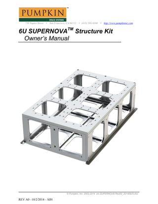
- 1. 750 Naples Street • San Francisco, CA 94112 • (415) 584-6360 • http://www.pumpkininc.com © Pumpkin, Inc. 2003-2014 src:SUPERNOVA-Rev00_20140925.doc REV A0 –10/2/2014 – SJH 6U SUPERNOVATM Structure Kit Owner’s Manual
- 2. SUPERNOVATM Structure Kit User Manual © Pumpkin, Inc. 2003-2014 src:SUPERNOVA-Rev00_20140925.doc 2 REV A0 – 10/2/2014 Contents Applications ..............................................................................................3 Features.....................................................................................................3 1 SUPERNOVA System Overview..........................................................4 1.1 Introduction.........................................................................4 1.2 Specifications......................................................................4 1.3 Components List .................................................................5 1.4 Tools....................................................................................5 1.5 Chassis External Dimensions..............................................6 1.6 Chassis Internal Dimensions ...............................................7 1.7 The CSD..............................................................................8 1.8 Flight Configurations & Deployables .................................9 2 Chassis Assembly ................................................................................10 2.1 Assembly Overview..........................................................10 2.2 Preliminary Assembly.......................................................11 2.3 Final Assembly..................................................................12 3 Stack Assembly ...................................................................................13 3.1 The Unit Cube...................................................................13 3.2 Assembling Instrument Stacks..........................................14 3.3 Uniquely Shaped Equipment.............................................15 4 Care and Cleaning................................................................................16 5 References & Additional Resources....................................................17
- 3. SUPERNOVATM Structure Kit User Manual © Pumpkin, Inc. 2003-2014 src:SUPERNOVA-Rev00_20140925.doc 3 REV A0 – 10/2/2014 APPLICATIONS Highly configurable 6U CubeSat structure for rapid integration of enhanced CubeSat missions FEATURES 6U-size CubeSat Structure 7000cc payload volume Compatible with Planetary Systems Corporation (PSC) Canisterized Satellite DispenserTM Anodized 7071 base plate provides a predictable load path within launcher Modular architecture allows a wide range of bus configurations and flight orientations Structure can accommodate 6 full-sized 10x10x10cm CubeSats with additional room available for cable routing, external instruments, solar panels, etc. Accommodates PSC Separation Connector for passing power & data to CubeSat bus while inside dispenser Over 10kg allowable mass in addition to structure Included covers allow for easy RF shielding
- 4. SUPERNOVATM Structure Kit User Manual © Pumpkin, Inc. 2003-2014 src:SUPERNOVA-Rev00_20140925.doc 4 REV A0 – 10/2/2014 1 SUPERNOVA SYSTEM OVERVIEW 1.1 Introduction Pumpkin’s SUPERNOVATM series 6U CubeSat structure kit provides a platform for rapid integration of mission hardware into a flight ready CubeSat spacecraft. The precision machined chassis allows a high level of configurability while maximizing the available mass and volume for payload. The SUPERNOVATM structure has been thoroughly tested for shock and vibration durability and each chassis fully conforms to the specifications required for use with Planetary Systems Corporation’s 6U Canisterized Satellite DispenserTM (hereon referred to as CSD). The modular nature of the SUPERNOVATM enables satellite subsystems to be assembled and tested in units, or stacks, external to the flight chassis. This allows for distributed development and ease of re-configuration in response to mission demands. In addition to the basic chassis assembly, the SUPERNOVATM structure kit comes with a selection of mounting hardware, covers, and adapters to accommodate a range of possible layouts. 1.2 Specifications All references to coordinates with regard to the SUPERNOVATM structure follow the position and orientation set out by the CSD specification. The XZ plane is coincident with the lower surface of the tabs. The ZY plane is centered between the outer edges of the tabs. The XY plane lies 8.5mm from the outer surface of the rear (-Z) panel with separation connector. FIGURE 1: REFERENCE COORDINATES TABLE 1: STRUCTURE PARAMETERS (W/O COVERS) PARAMETER VALUE UNITS Empty chassis mass 1.64 kg Total allowable mass in CSD 12.00 kg Internal volume 7000 cc Overall width (-X, +X) 239.2 mm Overall height (-Y, +Y) 105.6 mm Overall length (+Z) 365 mm Center of mass, X 0 mm Center of mass, Y 51 mm Center of mass, Z 183 mm
- 5. SUPERNOVATM Structure Kit User Manual © Pumpkin, Inc. 2003-2014 src:SUPERNOVA-Rev00_20140925.doc 5 REV A0 – 10/2/2014 1.3 Components List TABLE 2: CHASSIS ASSEMBLY COMPONENTS QTY COMPONENT PUMPKIN P/N MATERIAL 1 Base Plate 703-01040 Al-7075 1 Top Plate 703-01041 Al-6061 1 Y Wall 703-01042 Al-6061 1 Z Wall 703-01043 Al-6061 1 Y Wall Sep Conn 703-01049 Al-6061 1 Z Wall Sep Conn 703-01050 Al-6061 1 Separation Connector Bracket 703-01051 Al-6061 29 Screw, M3x12mm Flat Socket Head N/A 18-8 SS TABLE 3: ADDITIONAL COMPONENTS & SPARES QTY COMPONENT PUMPKIN P/N MATERIAL 5 Stack Adapter A 703-01044 Al-6061 5 Stack Adapter B 703-01045 Al-6061 3 Stack Extender 703-01046 Al-6061 10 Side Cover 703-01047 Al-6061 12 Extended Cover 703-01048 Al-6061 16 Threaded Rod, M3 x 75mmL 631-00884 Steel 8 Threaded Rod, M3 x 180mmL 631-00885 Steel 4 Threaded Rod, M3 x 286mmL 631-00977 Steel 40 Threaded F/F Standoff, M3 x 15mmL, 6mm Hex N/A Aluminum 72 Spacer, M3-Thru, 15.24 (0.600”) x 6mm OD N/A Aluminum 4 Screw, M3x12mm Flat Socket Head N/A 18-8 SS 96 Screw, M3x8mm Flat Socket Head N/A 18-8 SS 92 Screw, M2.5x4mm Flat Socket Head N/A 18-8 SS 1.4 Tools A 1.5mm and 2mm hex driver are included with the structure kit for preliminary assembly and disassembly. It is recommended that an electronic torque wrench is used for final assembly.
- 6. SUPERNOVATM Structure Kit User Manual © Pumpkin, Inc. 2003-2014 src:SUPERNOVA-Rev00_20140925.doc 6 REV A0 – 10/2/2014 1.5 Chassis External Dimensions FIGURE 2: EXTERNAL DIMENSIONS - SIDE FIGURE 3: EXTERNAL DIMENSIONS – TOP FIGURE 4: ALLOWABLE VOLUME OUTSIDE CHASSIS
- 7. SUPERNOVATM Structure Kit User Manual © Pumpkin, Inc. 2003-2014 src:SUPERNOVA-Rev00_20140925.doc 7 REV A0 – 10/2/2014 1.6 Chassis Internal Dimensions FIGURE 5: CELL LAYOUT & MOUNTING HOLE PATTERN FIGURE 6: INTERNAL DIMENSIONS - TOP VIEW FIGURE 7: CUTAWAY - CELL CROSS SECTION
- 8. SUPERNOVATM Structure Kit User Manual © Pumpkin, Inc. 2003-2014 src:SUPERNOVA-Rev00_20140925.doc 8 REV A0 – 10/2/2014 1.7 The CSD SUPERNOVATM is designed specifically for use with Planetary Systems Corporation’s Canisterized Satellite DispenserTM (CSD) & meets all payload dimensional specifications outlined in the CSD payload specification (2002367 Rev A). Note that the CSD specification also requires a set of contact points and inhibit switches which are not included in the base SUPERNOVATM structure kit. A Pumpkin CSD inhibit switch module is forthcoming. FIGURE 8: SUPERNOVA TM SPACECRAFT DEPLOYING FROM CSD SUPERNOVATM supports the use of Planetary Systems Corporation’s Separation Connector for signal and power routing while in the dispenser. The PSC Separation Connector is optional and not included with the SUPERNOVATM Structure Kit. It is available for purchase from Planetary Systems Corporation. FIGURE 9: PSC SEPARATION CONNECTOR & MOUNTING BRACKET
- 9. SUPERNOVATM Structure Kit User Manual © Pumpkin, Inc. 2003-2014 src:SUPERNOVA-Rev00_20140925.doc 9 REV A0 – 10/2/2014 1.8 Flight Configurations & Deployables SUPERNOVATM enables flexibility in flight orientation and deployable solar panel configuration. Shown below are 3 possible configurations. Deployable solar panels and bus electronics can be purchased separately from Pumpkin Inc. FIGURE 10: EXAMPLE FLIGHT CONFIGURATIONS
- 10. SUPERNOVATM Structure Kit User Manual © Pumpkin, Inc. 2003-2014 src:SUPERNOVA-Rev00_20140925.doc 10 REV A0 – 10/2/2014 2 CHASSIS ASSEMBLY 2.1 Assembly Overview A high level of symmetry and minimal number of fastener types ensures that SUPERNOVATM assembly is quite straightforward. The chassis is composed of seven main components, which are fastened together by 29 M3-0.5 x 12mm long flat-head screws, as well as up to 22 cover panels fastened by M2.5-0.4 x 4mm long flat head screws. FIGURE 11: SUPERNOVA TM CHASSIS ASSEMBLY TABLE 4: FIGURE 11 KEY ITEM # PART NUMBER DESCRIPTION QTY. 1 703-01040 Base Plate 1 2 703-01042 Y Wall 1 3 703-01049 Y Wall Sep Conn 1 4 703-01043 Z Wall 1 5 703-01050 Z Wall Sep Conn 1 6 703-01041 Top Plate 1 7 703-01051 Sep Conn Bracket 1 8 703-01047 Side Cover 10 9 703-01048 Extended Cover 12 10 N/A Screw, M2.5 FlatPhil 88 11 N/A Screw, M3 Flat Socket 29
- 11. SUPERNOVATM Structure Kit User Manual © Pumpkin, Inc. 2003-2014 src:SUPERNOVA-Rev00_20140925.doc 11 REV A0 – 10/2/2014 Parts 703-01040, 703-01042, 703-01043, & 703-01041 are symmetric in 2 planes so their assembly orientation doesn’t matter as long as the correct side is facing outward. Parts 703-01049 & 703-01050 have cutout features to allow for a PSC separation connector. The cutouts must be oriented such that they are closer to the base plate than the top plate. Part 703-01051 is a removable bracket for mounting the separation connector. It is externally removable to make wiring easier. In general, the spacecraft should be built up from the tabbed base plate since this is the part that is most critical with regards to dispenser compatibility. The general process for building up a SUPERNOVATM based 6U satellite is as follows: 1. Build up subsystem stacks externally to chassis (see section 3 – Payload Integration). 2. Orient and fasten stacks loosely to Base Plate. 3. Route cabling between stacks. 4. Mount Y and Z Walls. 5. Attach wall mounted instruments, etc. and route cabling. 6. Attach Top Plate. 7. Attach external panels, covers, deployable panels, antennas etc. 8. Follow procedure in section 2.3 Final Assembly to prep and torque fasteners for flight. FIGURE 12: ‘3U’ STACK MOUNTED TO BASEPLATE 2.2 Preliminary Assembly For preliminary assembly, it is recommended that all M3 fasteners to be used are inserted and loosely engaged before tightening any of them, then, gently hand-tighten each screw. Every component and screw should come together easily during assembly– avoid using force to engage fasteners or align components.
- 12. SUPERNOVATM Structure Kit User Manual © Pumpkin, Inc. 2003-2014 src:SUPERNOVA-Rev00_20140925.doc 12 REV A0 – 10/2/2014 2.3 Final Assembly To ensure that fasteners do not vibrate loose during launch, it’s important that during final assembly, the following procedures are followed. Check each threaded hole for residue or contamination Clean all bolts and threaded holes with isopropyl alcohol Clear and dry each threaded hole with compressed air Apply Loctite® 222MS thread locking compound to screw threads* Insert screw and use electronic torque wrench to tighten according to table 5 below. TABLE 5: FINAL ASSEMBLY TORQUE SPECIFICATIONS SCREW THREAD SIZE TORQUE (NM) M3-0.5 0.45(1) *The use of Loctite® thread-locking compounds in space equipment is not universally accepted. Pumpkin has successfully used this method to lock fasteners on multiple successful nanosatellite missions. SUPERNOVA end-users are ultimately responsible for the proper application of locking compounds and tightening torques to fasteners.
- 13. SUPERNOVATM Structure Kit User Manual © Pumpkin, Inc. 2003-2014 src:SUPERNOVA-Rev00_20140925.doc 13 REV A0 – 10/2/2014 3 STACK ASSEMBLY 3.1 The Unit Cube SUPERNOVATM is based around the idea of a 10x10x10 cm ‘Unit Cube’ similar to the original CubeSat specification. This allows any equipment that is CubeSat compatible to fit within the SUPERNOVATM chassis. FIGURE 13: '1U' STACK OF PC104 BOARDS Included with the SUPERNOVATM structure kit are adaptor brackets that allow PC-104 compatible instrument boards to be built up into stacks and mounted to the chassis structure. These stacks can extend from 1 Unit Cube (‘1U’) up to 310+mm (‘3U’) in length. FIGURE 14: '1U', '2U', AND '3U' STACKS
- 14. SUPERNOVATM Structure Kit User Manual © Pumpkin, Inc. 2003-2014 src:SUPERNOVA-Rev00_20140925.doc 14 REV A0 – 10/2/2014 3.2 Assembling Instrument Stacks Begin with either Stack Adapter A or B (# 703-01044 or 703-01045). These are mirror images of one another and are designed to go on either end of a stack. With 4 M3 x 8mm screws and 4 threaded hex standoffs, attach the hex standoffs to the adapter as shown. The appropriately sized threaded rods can then be screwed into the hex standoffs to form a base and rails for sliding on PC-104 boards and standoffs. Next, PC-104 boards can be slid on to the assembly, adding thru- hole spacers between boards as needed. When desired stack height is reached, use 4 more hex standoffs to secure the stack, then fasten the opposite stack adapter onto the remaining end. FIGURE 15: STACK ASSEMBLY VIEW TABLE 6: FIGURE 15 KEY ITEM NO. PART NUMBER DESCRIPTION 1U/QTY. 1 703-01044 Stack Adapter A 1 2 703-01045 Stack Adapter B 1 3 N/A Standoff, Hex, F-F, M3 x 15 8 4(1) N/A Standoff, Round, Thru, M3 Varies 5(2) 631-00258 1U Threaded Rod 4 6 N/A Screw, M3 Flat Socket 8 Note (1): For stacks longer than 1U, #703-01046 Stack Extender, needs to be employed as a spacer, aligned with cell mounting holes. Note (2): For stacks longer than 1U, use the appropriate 2U or 3U threaded rod.
- 15. SUPERNOVATM Structure Kit User Manual © Pumpkin, Inc. 2003-2014 src:SUPERNOVA-Rev00_20140925.doc 15 REV A0 – 10/2/2014 For stacks longer than 1U, one or more Stack Extenders (#703-01046) must be used in place of thru-hole spacers to secure the center of the stack to the chassis. Note that Stack Adapters and Stack Extenders have a notch in one corner that will always align in a stack. Because of varying sizes of PC boards, connector heights, etc. various sizes of thru-hole spacers will likely be needed for building stacks and some spacer machining or grinding will usually be necessary for the adapter spacing to meet the base plate mounting hole pattern. A jig for easily building up stacks of the correct size will be available from Pumpkin in the future. Additional spacer lengths can be purchased directly from Pumpkin. 3.3 Uniquely Shaped Equipment Equipment that doesn’t fit into PC-104 stacks can also be used with SUPERNOVATM . Some third-party components will require custom mounting brackets to install. It is recommended that payloads that cannot make use of the provided adaptor brackets are attached to both the base plate and top plate. As a rule of thumb – each of the 6 cell areas of the SUPERNOVATM should have at least one rigid member fastened to both the base plate and top plate with at least 2 M3 screws per side. FIGURE 16: 3RD PARTY COMPONENT WITH CUSTOM BRACKET MAI-400 ADACS SHOWN
- 16. SUPERNOVATM Structure Kit User Manual © Pumpkin, Inc. 2003-2014 src:SUPERNOVA-Rev00_20140925.doc 16 REV A0 – 10/2/2014 4 CARE AND CLEANING Isopropyl alcohol can be used to clean all parts of the SUPERNOVATM structure Always use cotton/nylon inspection gloves when handling components to avoid marking and leaving residues SUPERNOVATM is shipped with orange covers on the CSD tabs. These can be left in place until the spacecraft is ready to be integrated into the CSD to protect the tabs from dirt and damage. Extra care should be taken to ensure that no dirt, oils, or other material (such as metal shavings) is present in or around tapped holes prior to inserting fasteners. FIGURE 17: SUPERNOVA TM STRUCTURE WITH TAB COVERS
- 17. SUPERNOVATM Structure Kit User Manual © Pumpkin, Inc. 2003-2014 src:SUPERNOVA-Rev00_20140925.doc 17 REV A0 – 10/2/2014 5 ADDITIONAL INFORMATION 5.1 CAD Models 3D CAD Models of the SUPERNOVATM structure are available for download from Pumpkin’s website. 5.2 CSD Specifications The following specifications were used in the design of the SUPERNOVATM and are available from Planetary Systems Corporation at www.planetarysystemscorp.com. Canisterized Satellite Dispenser (CSD) Data Sheet – 20022337B Payload for Canisterized Satellite Dispenser (CSD) Spec. Sheet – 200236B Data Sheet for 4000383 Rev A Separation Switch Assembly – 2002204 Rev – Data Sheet for Separation Connector Assembly – 2001025C 5.3 References 1. Latta, Robert C., “Structural Analysis of a 6U Cubesat Chassis,” M.S. thesis, Dept. Aeronautics & Astronautics, AFIT, Wright-Patterson Air Force Base, OH, 2014. 5.4 Acknowledgements Dr. Eric Swenson, AFIT Phillip Smith, AFIT Robert Latta, AFIT Walter Holemans, Planetary Systems Corp. Ryan Hevner, Planetary Systems Corp.