SlideShare a Scribd company logo
1 of 33
Download to read offline
#42
Editorial – July 2011 – The latest space mission : SMOS, GOCE and CRYOSAT
GreeƟngs all,
This month’s newsleƩer is devoted to the latest space mission and their use in physical oceasnography. A focus is here put on the possible physical oceanography
applicaƟons of the SMOS, GOCE and CRYOSAT missions.
SMOS (Soil Moisture and Ocean Salinity), launched on November 2, 2009, is the first satellite mission addressing sea surface salinity measurements from space. Realis-
Ɵc salinity maps have been obtained and preliminary validaƟon tests against in situ data indicate that the SMOS team is approaching its goals. SMOS will be a mile-
stone in the route for incorporaƟng salinity to operaƟonal remote sensing.
The GOCE (Gravity Field and Steady-State Ocean CirculaƟon) satellite, first core Earth Explorer mission from ESA’s Living Planet programme, was successfully launched
on March, 17th
2009. One primary objecƟve of the GOCE mission is to determine the Earth geoid with an accuracy of 1-2 cm for a spaƟal resoluƟon of 100 km. This is
an important supplementary step towards the beƩer esƟmaƟon of the ocean Mean Dynamic Topography, a key reference surface for the assimilaƟon of alƟmetric Sea
Level Anomalies into operaƟonal ocean forecasƟng systems.
ESA's CRYOSAT Earth Explorer mission was launched on 8 April 2010. Although its first mission is to provide the first satellite maps of sea-ice thickness, the CRYOSAT
mission is also operaƟng over ocean surfaces providing a new source of valuable alƟmeter measurements. It represents an addiƟonal alƟmeter ocean mission comple-
mentary to exisƟng Envisat, Jason-1 and Jason-2 missions in the operaƟonal mulƟmission processing chain of the SSALTO/DUACS system used in MyOcean.
The newsleƩer is presenƟng the following scienƟfic arƟcles: First, Font et al. present the characterisƟcs of the SMOS instrument, a summary of the sea surface salinity
retrieval from SMOS observaƟons and shows iniƟal results obtained one year and a half aŌer launch. At present there are sƟll several issues being addressed by the
SMOS team, mainly related to low level data processing but also to the retrieval of salinity from radiometric measurements, which prevent by now from reaching the
mission objecƟves in terms of salinity accuracy. However, realisƟc salinity maps have been obtained and will be presented. Second, Rio and Mulet carry out an inde-
pendent validaƟon of the different GOCE geoid models, in order to assess their accuracy and determine which one is beƩer suited for oceanographic applicaƟons and
Mean Dynamic Topography esƟmaƟon. Both the impact of the different methodologies used to compute the gravity fields as well as the contribuƟon of the four
months of supplementary data have been checked. Third, Dorendeu et al. present a dedicated experiment in order to esƟmate to which extent valuable ocean alƟ-
metric signals can be extracted from CRYOSAT data and how this opportunity mission could be merged with exisƟng Envisat, Jason-1 and Jason-2 missions in the oper-
aƟonal mulƟmission processing chain of the SSALTO/DUACS system. Finally, Meinvielle et al. are wriƟng on how to opƟmally improve the atmospheric forcing of long
term global Ocean simulaƟons with Sea Surface Temperature (SST) observaƟons. The objecƟve of their research is to develop a new assimilaƟon scheme based on
advanced staƟsƟcal methods that will use SST satellite observaƟons to constrain the surface forcing funcƟon of long term ocean circulaƟon simulaƟons.
The next October 2011 issue will be dedicated to the reanalysis and reprocessing products within MyOcean. We wish you a pleasant reading!
Newsletter
QUARTERLY
(leŌ panel) ArƟst’s view of SMOS in orbit with its Y-shaped antenna array
(right panel) Global map of surface salinity (psu) generated from 10 days of SMOS measurements in August
2010.
Credits: Font et al. this issue.
Quarterly Newsletter
Mercator Ocean
CONTENT
SMOS: AN EARTH EXPLORER MISSION TO OBSERVE OCEAN SALINITY WITH A NOVEL
TECHNOLOGY
By Jordi Font, Jacqueline Boutin, Nicolas Reul, Paul Spurgeon, Steven Delwart and the SMOS Ocean Salinity Team
AN OCEANOGRAPHIC ASSESSMENT OF THE PRELIMINARY GOCE GEOID MODELS
ACCURACY
By Marie-Hélène Rio and Sandrine Mulet
CRYOSAT2 : AN OPPORTUNITY MISSION FOR MYOCEAN AND OCEANOGRAPHY—FROM
THEORY TO PRACTICE
By Joel Dorandeu, Gerald Dibarboure, Sylvie Labroue, Cécile Renaudie, Nicolas Picot, Tommaso Parrinello
OPTIMALLY IMPROVING THE ATMOSPHERIC FORCING OF LONG-TERM GLOBAL OCEAN
SIMULATIONS WITH SEA-SURFACE TEMPERATURE OBSERVATIONS
By Marion Meinvielle, Pierre Brasseur, Jean-Michel Brankart, Bernard Barnier, Thierry Penduff, Jean-Marc Molines
3
12
20
24
#42—July 2011—3Mercator Ocean Quarterly Newsletter
SMOS: AN EARTH EXPLORER MISSION TO OBSERVE OCEAN SALINITY
WITH A NOVEL TECHNOLOGY
By Jordi Font(1)
, Jacqueline Boutin(2)
, Nicolas Reul(3)
, Paul Spurgeon(4)
, Steven Delwart(5)
and the SMOS
Ocean Salinity Team
1
Institut de Ciències del Mar CSIC / SMOS Barcelona Expert Centre, Barcelona, Spain
2
Laboratoire d’Océanographie et du Climat-Expérimentation et Approches Numériques / Institut Pierre Simon Laplace – UMR 7159 CNRS/IRD/
UPMC/MNHN, Paris, France
3
Laboratoire d'Océanographie Spatiale, Institut Français de Recherche pour l'Exploitation de la Mer, Plouzané, France
4
ARGANS Ltd, Plymouth, England, UK
5
ESRIN – European Space Agency, Frascati, Italy
Abstract
SMOS (Soil Moisture and Ocean Salinity), launched on November 2, 2009, is the first satellite mission addressing sea surface salinity measure-
ments from space. Its unique payload is MIRAS (Microwave Imaging Radiometer using Aperture Synthesis), a new two-dimensional interferome-
ter designed by the European Space Agency (ESA) and operating at the microwave L-band. This paper presents the characteristics of the instru-
ment, a summary of the sea surface salinity retrieval from SMOS observations and shows initial results obtained one year and a half after launch.
The pioneer nature of this mission, both from the technological and data processing points of view, implies many challenges that require continu-
ous improvements even the mission was declared operational in May 2010. At present there are still several issues being addressed by the
SMOS team, mainly related to low level data processing but also to the retrieval of salinity from radiometric measurements, which prevent by now
from reaching the mission objectives in terms of salinity accuracy. However, realistic salinity maps have been obtained and preliminary validation
tests against in situ data indicate we are approaching our goals. SMOS will be a milestone in the route for incorporating salinity to operational
remote sensing.
Introduction
On November 2, 2009 the European Space Agency successfully launched from northern Russia the first of its Earth Explorer Opportunity Mis-
sions (EEOM): SMOS, Soil Moisture and Ocean Salinity (Kerr et al., 2001). These are small format missions aimed at demonstrating new technol-
ogies to provide relevant new information for Earth observation from space, and are proposed to ESA by the scientific community through dedicat-
ed calls. The opportunity missions are complementing the Earth Explorer Core Missions (the first one being the Gravity field and steady-state
Figure 1: Artist’s view of SMOS in orbit with
its Y-shaped antenna array
SMOS: an earth explorer mission to observe ocean salinity with a novel technology
#42—July 2011—4Mercator Ocean Quarterly Newsletter
Ocean Circulation Explorer, GOCE, launched in March 2009) designed and implemented by ESA as part of the science and research component
of its Living Planet Programme.
SMOS was submitted to the first EEOM call in 1998, and selected for a feasibility study, and later detailed design and implementation, under the
format of an ESA-lead mission in cooperation with France (CNES) and Spain (CDTI); Yann Kerr (CESBIO, Toulouse) and Jordi Font (ICM-CSIC,
Barcelona) were appointed Lead Investigators for soil moisture and ocean salinity, respectively. After launch, an In Orbit Commissioning Phase
took place for six months and in May 2010 the mission was declared operational. However, due to the exploratory nature of the mission and the
pioneer payload and geophysical retrieval approach used, the algorithms at all levels are continuously being improved and general reprocessing
campaigns are envisaged to generate optimised products for the community of users.
SMOS, also known as the ESA’s water mission, is expected to be a fundamental step for the future operational provision of these two variables
that play a key role in the Earth water cycle (http://www.esa.int/esaLP/LPsmos.html). Figure 1 is an artist’s view of SMOS in orbit with the three
antenna arms and solar panels deployed.
MIRAS in SMOS: a new technology
The remote sensing of ocean salinity and soil moisture is based on a common feature of both geophysical variables: they modify the dielectric
properties of respectively seawater and soil. All bodies spontaneously emit electromagnetic radiation in a large range of wavelengths. At low fre-
quencies, including microwaves, the brightness temperature of the body (TB, the quantity to be measured by a radiometer, and related to the emit-
ted power) is proportional to its physical temperature. The proportionality coefficient, the emissivity, is a function, among other variables, of the
dielectric constant and as a consequence of the conductivity, and hence salinity when the emitting body is seawater (see e.g. Lagerloef and Font
2010). SMOS was proposed to measure TB with a microwave radiometer to determine from it sea surface salinity (SSS) over the oceans and soil
moisture over land surfaces.
The SMOS radiometer operates at 1.413 GHz (within L-band), close to the maximum sensitivity of TB to changes in salinity and soil moisture and
where the impact of other parameters influencing it is minimal. [1.400-1.427] GHz is a frequency band where human made emissions are banned
by international regulations since it is kept for passive observations. The principles of SSS and soil moisture determination by microwave radiome-
try were sufficiently known for decades, but no satellite mission had attempted so far to measure these variables due to the very large scanning
antennas required to obtain a reasonable spatial resolution (few tens of km) at this frequency.
In order to overcome this problem SMOS is using a large number of small antennas (20 cm diameter), deployed along three 4 m arms forming a Y
shape. This is the same principle used in radioastronomy for more than 50 years to achieve a very large synthetic antenna from an array of anten-
nas distributed on ground. This instrumental design, known as MIRAS (Microwave Imaging Radiometer using Aperture Synthesis), is the result of
an innovative technological concept developed by ESA (McMullan et al., 2008) through the implementation in two dimensions of synthetic aper-
Figure 2: MIRAS, the SMOS two-dimensional inter-
ferometric microwave radiometer, being assembled
at EADS CASA Espacio, Madrid
SMOS: an earth explorer mission to observe ocean salinity with a novel technology
#42—July 2011—5Mercator Ocean Quarterly Newsletter
ture radiometry, first proposed for Earth observation by LeVine and Good (1983) and Ruf et al. (1988) as a way to increase the angular resolution
of individual antennas.
MIRAS (figure 2) is the first ever interferometric radiometer onboard a satellite. Cross-correlations between the signals collected by all pairs of 69
small antennas are measured every 1.2 seconds. After a process of internal and external calibration, these correlations, together with the average
TB measured at low spatial resolution by three dedicated radiometers on board, become the so-called complex visibility, a two-dimensional func-
tion of the relative distance between antennas in each pair. In a first-order approximation, the source TB image, as a function of the spatial direc-
tions, is equal to the two-dimensional Fourier transform of this visibility function (Corbella et al. 2004). The image is then retrieved from the cali-
brated visibility by using a suitable inversion algorithm. In the end, this can be shown to be equivalent to synthesizing a narrow antenna beam at
each spatial direction or pixel. The principal advantage of this technique is that, unlike a classical total power radiometer, it does not require any
mechanical scanning to achieve a complete map of brightness temperature: One full image snapshot is obtained at a time every 1.2 seconds in
the case of SMOS. On the other hand, the image has multiple incidence angles, mixed polarisation and different radiometric quality (sensitivity
and resolution) depending on the spatial direction.
The development and manufacturing of MIRAS has been a large technological challenge. Besides the innovative instrumental concept itself, it
includes many state-of-the-art subsystems and some of them (for example the optical harness) provide solutions that have been implemented in
space for the first time. Up to now, after more than one year and a half from launching, it continues to operate successfully with all parameters
within their expected range of variation. Details on MIRAS and interferometric polarimetric radiometry can be found in Font et al. (2010), together
with abundant bibliographic references.
Determining salinity from SMOS measurements
SMOS is orbiting at 755 km, has a repeat cycle of 144 days (almost repeat in 18 days), and the antenna plane is tilted 32.5º from horizontal. This
way the spatial coverage is maximised and any point on Earth is sampled at least once every 3 days, a requirement for soil moisture observations
(Waldteufel et al., 2003). The reconstructed SMOS TB images are curved hexagons, almost 1000 km wide, formed by pixels from 30 to 100 km,
with varying incidence angle and radiometric resolution depending on their location with respect to the antenna boresight in each snapshot.
At each SMOS overpass salinity is determined by comparing, for any single spot at the ocean surface, the measured TB at different incidence
angles while the spot is inside the field of view in successive satellite snapshots, to the TB theoretically emitted by the ocean at the corresponding
angles. The latter is computed by a forward model of the ocean emission taking into account the actual seawater conditions. A cost function is
minimised in a convergence loop, where the value of SSS is corrected from a first guess until an optimal fit with the measured TB is reached. The
relationship between temperature, salinity, angle of observation, frequency and the radiation polarisation state with the microwave brightness
temperature is given, from basic principles, only for a flat-sea condition. The effect of the sea roughness upon TB, the main source of geophysical
error in salinity remote sensing (Yueh et al. 2001), is taken into account as a correction to the flat-sea value. Information on roughness is derived
from operational forecasts of wind and wave characteristics from the European Centre for Medium-range Weather Forecast that also provides
other auxiliary information required as sea surface temperature or atmospheric parameters. Moreover, further corrections must be made consider-
ing that the emitted radiation is modified in its path from the surface to the satellite (attenuation by the atmosphere, polarisation mixing in the iono-
Figure 3: Salinity retrieval approach with SMOS. (left panel) Different sources of L-band radiation that can reach the radiometer; (right panel)
Block diagram of the SMOS salinity processor, from filtering degraded measurements to recovering three different salinity values using three
alternative roughness correction models.
SMOS: an earth explorer mission to observe ocean salinity with a novel technology
#42—July 2011—6Mercator Ocean Quarterly Newsletter
sphere, …), and other sources of radiation at the same frequency may exist that can also reach the radiometer (emission by the atmosphere,
galactic radiation scattered on the surface, …). The result is a quite complex algorithm implemented in the SMOS salinity processor (Zine et al.
2008) that includes a series of sequential modules (figure 3), from filtering out erroneous or low quality TB and auxiliary data, to models of all the
involved physical processes, and to the SSS retrieval scheme and generation of the SMOS salinity product. This output product, known as level 2
(geophysical variable, in this case retrieved salinity, in a per orbit basis), is distributed by ESA as strips over ocean areas centered along the satel-
lite subtrack.
The multiangular measurement characteristics of SMOS should allow for a redundant determination of SSS. However, it was estimated during the
mission development that radiometric noise and other possible errors (mainly due to the instrument performance limitations, image reconstruction
process, errors on auxiliary parameters, and incomplete forward model formulation) would result in accuracy in retrieved SSS of the order of 1-2
salinity units. The high level of noise in single orbit SSS determinations should be reduced by spatial and temporal averaging, that is generating
salinity maps from the level 2 products. The integration of several SMOS orbits in a temporal window of 10-30 days and spatial resolution of 100-
200 km can provide a product similar to present climatologies but including the temporal evolution. The goal is to achieve salinity accuracy of the
order of 0.1 salinity units, which is relevant to the study of large scale oceanographic and climatic phenomena, like the observation and forecast of
El Niño events, the North Atlantic thermohaline circulation, or the estimation of open ocean precipitation (Font et al., 2004).
The ESA mandate for SMOS is to design, implement, launch, and operate the mission during its entire life (nominal 3 years, expected 5 years and
even beyond), and to deliver products to users up to level 2, as well as maintaining a long-term archive. A near-real time processing chain has
also been set up following the demand of operational meteorological institutions, like ECMWF or the Meteorological Service of Canada. Both cen-
tres are now monitoring and plan to assimilate soon SMOS level 1 (brightness temperature) data over land into their numerical weather systems.
In order to generate higher level products, both France and Spain committed to design, fund, implement and operate additional SMOS data pro-
cessing centers. While these additional products are, in a first stage, global gridded maps (level 3), later products will be proposed through the
integration of the SMOS data with other sources of information (level 4), both from Earth observation satellites, as the US-Argentina Aquarius
salinity mission (Lagerloef et al. 2008) launched on 10 June 2011, and from in situ measurement systems. The French Centre Aval de Traitement
de Données SMOS (CATDS) is installed in the Institut français de recherche pour l’exploitation de la mer (IFREMER, Brest), while the Spanish
Centro de Proceso de datos SMOS de niveles 3 y 4 (CP34) is operating in the European Space Astronomy Centre (ESAC, near Madrid) next to
the official ESA SMOS Data Processing Ground Segment.
First results and remaining issues
Soon after MIRAS switching-on and first calibrations, level 1 data (TB) were available from December 2009 onwards and the characteristics of the
reconstructed images field and their impact on the level processing could be examined. As explained before, MIRAS is performing according to
the specified requirements, or even better. Measured radiometric sensitivity over the oceans is in agreement with theory, thermal noise is negligi-
ble after calibration, and the instrument appears to be reasonably stable over several months. Therefore, from an instrumental point of view, the
TB images are currently generated operationally with good quality. However, corrections applied to the routine radiometer calibrations and some
aspects of image reconstruction procedures still need to be refined for an optimal SSS product, while some components of the forward model,
Figure 4: The strong salinity
(psu) gradient of the Amazon
plume measured by SMOS in
August 2010
SMOS: an earth explorer mission to observe ocean salinity with a novel technology
#42—July 2011—7Mercator Ocean Quarterly Newsletter
mainly the roughness correction module (designed before launch), are being improved through analysis of real SMOS data. Nevertheless, the first
salinity retrieval tests performed by the SMOS L2OS (L2 Ocean Salinity) processor showed meaningful geophysical signals, such as the expected
latitudinal salinity variation along an ascending orbit in the Pacific Ocean and the strong gradients associated to the Amazon plume (figure 4).
Figure 5 shows the first satellite salinity map generated in early February 2010 by combining ten SMOS ascending orbits acquired in late January
in the Pacific without data filtering or averaging. This SSS field was retrieved using a simplified algorithm instead of the full L2OS processor, for a
first retrieval test from the SMOS level1 products. A comparison of SMOS to the January surface salinity climatology from the World Ocean Atlas
2005 (Antonov et al., 2006) shows a considerable coherence both in terms of spatial structure and absolute values. Degraded results are found
near the swath borders, where the number of TB measurements for each grid point is the smallest and where the radiometric quality is poor, and
also near the coast. The plot also shows areas of strong winds in high North and South latitudes where roughness correction models seem not to
be reliable enough and the sensitivity of TB to SSS is minimal due to low sea surface temperatures.
Font et al. (2011) present a summary of the main issues that are now affecting the quality of the SSS retrieved by SMOS. By May 2011 new ver-
sions of the level 1 and level 2 processors have been delivered and will be ingested in the processing chain, as well as used in autumn this year
for a general reprocessing of all the data from the beginning of the mission. A note for the SMOS swath ocean salinity products users has been
prepared by the authors and is being displayed in the ESA web site:
“The present OS level 2 processor, which includes the last corrections and improvements as result of the data analysis during and beyond the
Commissioning Phase, is ready to deliver the best salinity products available, although still not reaching the expected quality, with several issues
under study by the development team. Details on the processing algorithms can be found in the Algorithm Theoretical Baseline Document
(ATBD), and on the L2OS products structure in the SMOS Level 2 and Auxiliary Data Products Specifications, both available from ESA (all docu-
ments available on www.earth.esa.int/smos). Additional information, including documentation, product thumbnails and FAQs, can also be found
on the SMOS L2OS website: www.argans.co.uk/smos.
Users should be aware that by now these L2OS products are to be intended more for diagnosing and improving the SMOS salinity retrieval than
for their operational use in oceanographic research.
The following comments have to be taken into account for a proper understanding, interpretation and assessment of the OS products:
The released SMOS salinity products are not yet validated. They are the result of applying the algorithms described in the ATBD that will evolve
from the experience gained with several months of data analysis, and from the feedback provided by the SMOS validations teams, which started
working in July 2010. A general reprocessing is expected to take place summer 2011 after new corrections and improvements at all levels.
Three different salinity values are included for each grid point of the L2OS products. These correspond to the three roughness effect model op-
tions included in the retrieval, as described in the ATBD. These models have been tuned and modified to improve retrievals, and will continue to
be refined for the 2011 reprocessing. Hopefully in the future a unique optimal salinity value will be delivered.
The SMOS L2 OS User Data Product contains many flags and descriptors to help understanding the characteristics and circumstances of the
salinity products generation. These are described in the above referenced documents. Missing salinity values are indicated by -999. Since March
2011 a new algorithm for calculating the quality index (Dg_quality_SSS), and new quality flags, have been introduced into the L2OS User Data
Product, which may be used to filter grid points, for example where good quality salinity has been retrieved, or where specific geophysical condi-
tions may have an impact on retrieval quality: for details see Fg_ctrl_poor_quality and Fg_ctrl_poor_geophysical in the Input/Output Data Defini-
tion (http://www.argans.co.uk/smos/docs/deliverables/delivered/IODD/SO-TN-ARG-GS-0009_L2OS-IODD_v2.18_101207.pdf).
SMOS salinity retrieval is based on a comparison between measured (L1c products, at antenna level, not surface level) and modeled (ocean sur-
face emission including salinity contribution) brightness temperatures. After MIRAS being optimally calibrated, there is still a residual average
Figure 5: First SMOS salinity (psu)
map obtained by superposing 10 as-
cending orbits over the Pacific Ocean
in December 2009 (by J. Tenerelli,
CLS, Brest) compared to World
Ocean Atlas 2005 climatology.
SMOS: an earth explorer mission to observe ocean salinity with a novel technology
#42—July 2011—8Mercator Ocean Quarterly Newsletter
misfit between measured and modeled TB over homogeneous ocean areas probably due to instrumental and image reconstruction method imper-
fections. The resulting bias has a persistent spatial pattern as seen in the antenna cosinus-director frame that is now removed in the processor by
introducing Ocean Target Transformation Look Up Tables) to the L1 TB before running salinity forward models. This transformation basically con-
sists in applying a constant offset (positive or negative) to the TB depending on their coordinates in the antenna frame (incidence and azimuth
angles). This step is now described as an appendix in the last version of the ATBD http://www.argans.co.uk/smos/docs/deliverables/delivered/
ATBD/SO-TN-ARG-GS-0007_L2OS-ATBD_v3.6_101207.pdf). Alternative bias removing methods are being tested and may be incorporated in
future versions of the L2OS processor.
Poorer quality retrieval can be seen near to the edges of each swath, where less TB measurements are available for each grid point and radio-
metric quality is poorer. This may be removed in further versions of the processor in case that only Alias-Free data are used, instead of Extended-
Alias-Free as implemented now. Anyway, the expected accuracy of the salinity retrieval at L2 is of the order of 1-2 psu depending on the distance
to satellite subtrack and other environmental conditions. To reach the 0.1-0.2 salinity units at GODAE scales stated in the SMOS mission objec-
tives, further spatio-temporal averaging is needed to reduce the noise level. This is to be done by the French CATDS and Spanish CP34 high
level SMOS data processing centres. CP34 is already operational and users can register at http://www.cp34-users.cmima.csic.es/.
A problem that can be observed in SMOS TB and salinity data is the contamination from land as soon as land masses enter the SMOS very wide
antenna field of view. This depends on the distribution of brightness temperature of the land masses far away from the scene for which SSS is
retrieved. This effect impacts the quality of the retrievals in spatial bands following the world continent major coast-lines and spanning over differ-
ent distances from coast, depending on the orbit orientation. A similar effect can be observed in ice-sea transition areas. The problem is thought
to be an image reconstruction issue and improvements are expected to be introduced in further versions of the L1 processor.
Another problem now under study is the impact of antenna temperature in the generated brightness temperatures. Seasonal TB drifts have been
observed, as well as differences between ascending and descending passes, and this appears to be due to the different position of the Sun with
respect to the antennas. These small drifts (that can reach up to 1 ºK in 6 months in the Extended-Alias-Free Field-of-View) are irrelevant for soil
moisture retrieval but not for salinity. New antenna pattern models and calibration corrections are being tested and will be incorporated in further
versions of the L1 processors.
Although not as dramatic as over land, SMOS ocean images can also be affected by radiofrequency interferences generated by illegal man-made
emissions, and this is especially important in some regions as in the Northern Atlantic. This is now under investigation to find efficient methods for
◄ Figure 6: A SMOS level 2 swath product (ascending
semi-orbit) generated with the latest versions of the L1
and L2 processors, not yet ingested in the production
chain. The image evidences the noisy character of the
retrieved salinity (psu) on a single satellite overpass,
and the effect of filtering out pixels that have been
found to be outliers or too close to land or sea ice.
▲ Figure 7: Global map of surface salinity (psu) generated from 10 days of SMOS
measurements in August 2010 reprocessed with the latest version of the level 1 and
level 2 processors, including removal of the main land contamination effects and with
improved roughness correction. White areas over the ocean indicate that data have
been filtered out due to low quality.
SMOS: an earth explorer mission to observe ocean salinity with a novel technology
#42—July 2011—9Mercator Ocean Quarterly Newsletter
identification and removal of contaminated data, as well as in the political/technical side to get the illegal sources being switched-off by the corre-
sponding national authorities (many successful actions have been achieved until now).
It can also be noticed that salinity retrieval is worse in cold oceans (TB sensitivity to SSS decreases with decreasing SST) and also in areas of
strong winds. The three roughness impact models now implemented in the L2OS processor (that generate three different SSS values) are per-
forming less well under strong winds. This is also being addressed by the algorithms development teams to find improved formulations, and the
L2 algorithm version operational from March 2011 includes new roughness correction algorithms fitted to SMOS data.
Significant differences are found between SSS retrieved in ascending and descending passes, particularly at high latitudes. Besides the drift prob-
lem mentioned above, this can also be related to sunglint effects. Although a method to flag and correct for sunglint contamination is implemented
in the processor, it seems to introduce an artificial bias which is seasonal and latitude dependent in descending passes. This may be a source for
the observed differences between passes, as the miss-match is dominant in the descending passes southern latitudes, for which sun glint is the
strongest.
Other imperfections in these products can be due to image reconstruction problems still to be solved or to the salinity retrieval process, from the
forward models to simulate the ocean emission and its fate until reaching the instrument antenna, until the inversion technique. Feedback from the
users in identifying problems and proposing solutions will be more than welcome.”
Several of the above mentioned issues have been significantly mitigated in the new versions of the processors that will be operational from sum-
mer 2011, especially short term drifts linked to variability of the antennas physical temperature and the strong land contamination around the con-
tinents that was beyond theoretical expectations (figure 6). Figure 7 is a global salinity map built offline from level 2 products by the SMOS Barce-
lona Expert Centre in June 2011 using the latest versions of the processors.
As mentioned herein, SMOS is a completely new Earth observation mission, both from the instrument and algorithmic points of view. Therefore,
the validation of the products it provides is the fundamental step to demonstrate the feasibility of the proposed approach for future operational
missions to regularly provide soil moisture and ocean salinity. The evolving situation, with continuous improvements of the algorithms, will allow
soon starting systematic validation activities. Evaluation of SMOS salinity data can be better performed using averaged maps than the much noisi-
er single level 2 products distributed by ESA. In exploratory tests the SMOS derived SSS maps have been compared to equivalent products from
in situ observations, namely the World Ocean Atlas climatologies and interpolated maps from the Argo array of drifting profiling floats.
Figure 8 displays the 10-day averaged SMOS SSS for the period February 6, 2011 through February 16, 2011 computed with the current opera-
tional SMOS products (that is before the last land contamination correction, not operational yet) minus surface salinity from WOA 2005 monthly
climatology. The activation of the processor error flags masks large portions of the North Atlantic, East Pacific, North Indian Ocean and Mediterra-
nean Sea that are regions systematically affected by interferences. The spatial distribution of the surface salinity displays coherent spatial struc-
tures of fresh anomalies in the open oceans in the tropical regions. Salty anomalies, too large compared with the known variability of the SSS
field, are observed for the Southern ocean and near coastal areas, and are supposed to be mainly due to the above mentioned strong land (and
ice) contamination effect. Analyzing for the same period the differences between SMOS and interpolated Argo data 7.5 m deep, we find that
SMOS SSS shows globally a bias of 0.3 psu with a standard deviation of 0.8 psu. This is really encouraging, especially taking into account
Figure 8: Field of SMOS SSS anoma-
ly (psu) with respect to World Ocean
Atlas 2005 climatology for the period
6 to 16 February 2011, computed
from the level 2 products operational-
ly delivered by the SMOS Data Pro-
cessing Ground Segment.
SMOS: an earth explorer mission to observe ocean salinity with a novel technology
#42—July 2011—10Mercator Ocean Quarterly Newsletter
(besides that SMOS samples the first cm while Argo provides subsurface information) that the recent processor modifications will allow improving
this situation, and that once SMOS level 1 will reach an optimum calibration and image reconstruction quality, there is still room for improvements
in the salinity retrieval through better roughness correction formulations.
Conclusion
Salinity microwave remote sensing has limitations due to the weak TB sensitivity to SSS that requires an excellent accuracy and stability of a radi-
ometer. For a fixed incidence angle, the entire range of salinity in the world oceans corresponds to about 5 ºK in TB, while this is up to 100 ºK for
the soil moisture range. SMOS is the first attempt to obtain this information from space with a novel technology, L-band interferometric radiometry,
never used before onboard a satellite. After one year of regular operations, the SMOS MIRAS instrument has demonstrated to comply with the
strict technical requirements and deliver the planned radiometric information. The complexity of the image reconstruction process that integrates
large area total power measurements with high angular resolution demands a very accurate low level data processing, still being refined. The
pioneer geophysical modeling, plus additional problems like the impact of illegal man-made emissions within the forbidden band or the effect of
external natural radiation (e.g. galactic noise) reaching the radiometer through scattering on the ocean surface, is also a real challenge. However,
we have been able to obtain realistic salinity retrievals and are significantly advancing into the generation of products useful for large scale ocean-
ographic studies, even the mission requirements may not be reached in some specific ocean areas. We expect demonstrating this is an adequate
approach for future missions to regularly deliver SSS information to complement the existing in situ observing systems (Lagerloef et al., 2011) and
hence improving our present capability to diagnose and forecast the state of the world oceans.
Acknowledgements
The design, implementation and operation of SMOS has been possible thanks to the effort of many scientific, technological and industrial Europe-
an teams for almost twenty years. The SMOS level 2 processor development was funded by ESA under different contracts. This work was also
supported in part by the French Centre National d’Etudes Spatiales, and by the Spanish National R+D Plan for the SMOS Barcelona Expert Cen-
ter on Radiometric Calibration and Ocean Salinity (http://www.smos-bec.icm.csic.es) activities, through project AYA2010-22062-C05 and previous
grants.
References
Corbella, I., Duffo N., Vall-llossera, M., Camps, A. and Torres, F. 2004: The visibility function in interferometric aperture synthesis radiometry.
IEEE T. Geosci. Remote 42:1677–1682.
Font, J., Lagerloef, G.S.E., Le Vine, D.M., Camps, A. and Zanifé, O.Z. 2004: The determination of surface salinity with the European SMOS space
mission. IEEE T. Geosci. Remote 42:2196-2205.
Font,, J., Camps, A., Borges, A., Martín-Neira, M., Boutin, J., Reu,l N., Kerr, Y.H., Hahne, A. and Mecklenburg, S. 2010: SMOS: The challenging
measurement of sea surface salinity from space. P. IEEE 98:649-665.
Font, J., Boutin, J., Reul, N., Spurgeon, P., Ballabrera-Poy, J., Chuprin, A., Gabarró, C., Gourrion, J., Hénocq, C., Lavender, S., Martin, N., Mar-
tínez, J., McCulloch, M., Meirold-Mautner, I., Mugérin, C., Petitcolin, F., Portabella, M., Sabia, R., Talone, M., Tenerelli, J., Turiel, A., Vergely, J.L.,
Waldteufel, P., Yin, X., Zine, S. and Delwart, S. 2011:. SMOS first data analysis for sea surface salinity determination. Int. J. Rem. Sens. (in
press).
Kerr, Y.H., Waldteufel, P., Wigneron, J.P., Martinuzzi, J.M., Font, J. and Berger M. 2001: Soil moisture from space: the Soil Moisture and Ocean
Salinity (SMOS) mission. IEEE T. Geosci. Remote 39:1729-1735.
Lagerloef, G.S.E., Colomb, F.R., Le Vine, D.M., Wentz, F., Yueh, S.H., Ruf, C., Lilly, J., Gunn, J., Chao, Y., deCharon, A., Feldman, G. and Swift,
C.T. 2008: The Aquarius/SAC-D mission designed to meet the salinity remote sensing challenge. Oceanography 21:68-81.
Lagerloef, G.S.E. and Font, J. 2010: SMOS and Aquarius/SAC-D missions: The era of spaceborne salinity measurements is about to begin. In: V.
Barale, J.F.R. Gower, L. Alberotanza (eds.), Oceanography from Space. Springer Science+Business Media B.V., pp. 35-58.
Lagerloef, G.S.E., Boutin, J,. Chao, Y., Delcroix, T., Font, J., Niiler, N., Reul, N., Schmitt, R., Riser, S., Stammer, D. and Wentz, F. 2011: Resolv-
ing the global surface salinity field and variations by integrating satellite and in situ observations. In: Hall J., Harrison D.E., Stammer D. (eds.),
Proceedings of OceanObs'09: Sustained Ocean Observations and Information for Society (Vol. 2), ESA Publication WPP-306 (in press)
SMOS: an earth explorer mission to observe ocean salinity with a novel technology
#42—July 2011—11Mercator Ocean Quarterly Newsletter
LeVine, D.M. and Good, J.C. 1983: Aperture synthesis for microwave radiometers in space. NASA Technical memorandum 85033.
McMullan, K., Brown, M., Martín-Neira, M., Rits, W., Ekholm, S., Marti, J. and Lemanzyk, J. 2008: SMOS: The payload. IEEE T. Geosci. Remote
46:594-605.
Ruf, C.S., Swift, C.T., Tanner, A.B. and Le Vine, D.M. 1988: Interferometric synthetic aperture microwave radiometry for the remote sensing of the
Earth. IEEE T. Geosci. Remote 26:597-611.
Waldteufel, P., Boutin, J. and Kerr, Y.H. 2003: Selecting an optimal configuration for the Soil Moisture and Ocean Salinity mission. Radio Sci.
38:8051.
Antonov, J.I., Locarnini, R.A., Boyer, T.P., Mishonov, A.V. and Garcia, H.E. 2006: World Ocean Atlas 2005, Volume 2: Salinity, S. Levitus ed.,
NOAA Atlas NESDIS 62, U.S. Government Printing Office, Washington, D.C. 182 pp.
Yueh, S.H., West, R., Wilson, W.J., Li, F.K., Njoku, E.G. and Rahmat-Samii, Y. 2001: Error sources and feasibility for microwave remote sensing
of ocean surface salinity. IEEE T. Geosci. Remote 39:1049-1060.
Zine, S., Boutin, J., Font, J., Reul, N., Waldteufel, P., Gabarró, C., Tenerelli, J., Petitcolin, F., Vergely, J.L., Talone, M. and Delwart, S. 2008:
Overview of the SMOS sea surface salinity prototype processor. IEEE T. Geosci. Remote 46:621-645.
SMOS: an earth explorer mission to observe ocean salinity with a novel technology
#42—July 2011—12Mercator Ocean Quarterly Newsletter
AN OCEANOGRAPHIC ASSESSMENT OF THE PRELIMINARY GOCE GEOID
MODELS ACCURACY
By Marie-Hélène Rio(1)
and Sandrine Mulet(1)
(1)
CLS / Space Oceanography Division, Ramonville Saint-Agne, France
INTRODUCTION
The GOCE (Gravity Field and Steady-State Ocean Circulation) satellite, first core Earth Explorer mission from ESA’s Living Planet programme,
was successfully launched on March, 17th
2009. One primary objective of the GOCE mission is to determine the Earth geoid with an accuracy of 1
-2 cm for a spatial resolution of 100 km. After the success of the GRACE mission (launched in March 2005, and still operating), which exploitation
has allowed to improve the geoid knowledge at scales greater than 300km, this is an important supplementary step towards the better estimation
of the ocean Mean Dynamic Topography, a key reference surface for the assimilation of altimetric Sea Level Anomalies into operational ocean
forecasting systems.
Two years after launch, six preliminary GOCE geoid models have been made available, based on three different computational approaches. For
each approach, two releases have been made, the first one in June 2010, based on 2 months of GOCE data, and the second one in March 2011,
based on more than 6 months of data.
In this study, an independent validation of the different GOCE geoid models has been carried out in order to assess their accuracy and determine
which one is better suited for oceanographic applications, if any. Both the impact of the different methodologies used to compute the gravity field
as well as the contribution of the four months of supplementary data have been checked.
Section 2 gives more details about the different GOCE geoid models available. The assessment method developed to assess the accuracy of the
different solutions is presented in section 3 and the results are analyzed in section 4. Section 5 gives the main conclusions and perspectives of
this study.
GOCE data
The ESA HPF (High Processing Facility) has used three different approaches to compute the GOCE geoid models (Pail et al, 2011). The time-
wise (Pail et al, 2010) and the space-wise (Migliaccio et al, 2010) approaches have been especially developed for the GOCE mission while the
direct approach (Bruinsma et al, 2010) is more classical. Two releases computed from respectively 2 months and 6 months of GOCE data are
available for each geoid models based on the time-wise and the direct approaches. Only one release based on the space-wise approach is availa-
ble and uses 2 months of GOCE data.
The two releases based on the direct approach (EGM_DIR_R1 and EGM_DIR_R2) are developed to order and degree 240 of spherical harmon-
ics (83 km resolution). EGM_DIR_R1 results from 2 months of GOCE data constrained toward Eigen_51C that combines surface and GRACE
data (Bruinsma et al, 2010) while EGM_DIR_R2 results from 6 months of GOCE data constrained toward ITG_Grace2010s that is a GRACE
(Gravity Recovery And Climate Experiment) only solution (Kurtenbach et al, 2009). The first release based on the time-wise approach
(EGM_TIM_R1) is developed to order and degree 224 of spherical harmonics (89 km resolution) while the second release (EGM_TIM_R2) is de-
veloped to order and degree 250 (80 km resolution). EGM_SPW is based on the space-wise approach and is developed to order and degree 210
of spherical harmonics (95 km resolution).
METHOD
In order to investigate the quality of the new GOCE geoid models we have first computed MDTs from EGM_DIR, EGM_SPW and EGM_TIM. To
quantify the improvement of GOCE relative to GRACE mission we have also computed MDT from ITG-Grace2010s developed to order and de-
gree 180 and using seven years of GRACE data (Kurtenbach et al, 2009).
The MDTs are computed by subtracting the different geoid models from an altimetric Mean Sea Surface. The Mean Sea Surface (MSS) used in
this study is the MSS_CNES_CLS10 estimated for the 1993-1999 period (Schaeffer et al, 2010). The MSS resolves spatial scales as short as 10-
20 km while the geoid models are developed up to degree and order 210-250 (i.e. 95-80 km resolution) for the GOCE solutions and up to degree
An oceanographic assessment of the preliminary GOCE geoid models accuracy
#42—July 2011—13Mercator Ocean Quarterly Newsletter
and order 180 (i.e. 111 km resolution) for the GRACE solution. Further filtering is hence needed. We applied a gaussian filter using for the resolu-
tion scales six different values (100, 125, 150, 200, 250 and 350 km).
In this study, we have mainly focused on the geostrophic currents deduced from the MDTs that are an estimation of the MDT gradients and thus
are more sensible to noise than the MDT itself. Moreover it is more convenient to have a reliable estimate of geostrophic currents from in-situ data
than an estimate of height above geoid. The estimate of the mean geostrophic currents (called ‘synthetic’ currents in the following) is deduced
from all the 15 meter drogued drifting buoy data collected from 1993 to 2008 in the framework of the international WOCE and TOGA Surface Ve-
locity Program. These data are distributed by AOML where they first have been quality controlled and krigged (Hansen and Poulain, 1996) in or-
der to provide 6-hourly velocity measurements. In order to extract from the drifting buoy velocities only the geostrophic component, the Ekman
current was first modelled (Rio and Hernandez, 2003) and substracted. Then, a 3 day low pass filter was applied to the velocities to remove iner-
tial and tidal currents as well as residual high frequency ageostrophic currents. Finally the geostrophic velocity anomalies deduced from the Sea
Level Anomalies relative to the 1993-1999 period are interpolated along the drifter’s trajectories and subtracted from the associated instantaneous
geostrophic currents to have an estimate of the mean geostrophic currents relative to the same 7 year period. The altimetric SLAs used in this
study are computed by the SSALTO/DUACS centre and distributed by AVISO (SSALTO/DUACS User Handbook, 2006). The synthetic currents
obtained as described above are then filtered at the same resolution scales and using the same Gaussian filter than the MDTs computed from
geoid models.
Standard deviations of the differences between the geostrophic currents associated with MDTs computed from geoid models and synthetic geo-
strophic currents deduced from independent observations are computed at different resolution scales. The results will be discussed in the follow-
ing sections.
IMPROVEMENT OF GOCE OVER GRACE
Figure 1 shows, at different resolution scales, the standard deviation of the difference
between synthetic geostrophic current and geostrophic velocities estimated from GRACE and GOCE MDTs. In this part, only the first releases of
the GOCE geoid models computed with 2 months of data are used.
At scales smaller than 200 km, the standard deviations of the difference are much smaller with MDTs computed with GOCE geoid models (blue
lines) than with GRACE geoid model (pink lines). At 100km, GOCE improves a lot the comparisons to independent observations; the gain of
EGM_TIM_R1 compared with ITG_Grace2010s is 72% for the zonal velocities and 68% for the meridional
velocities. In the Gulf Stream area (Figure 2) the circulation is well described by MDTs computed with GOCE data while MDT computed with







 −
−
−
2
2010
2
_
2
2010
sGraceITG
TIMEGMsGraceITG
σ
σσ
Figure 1: Standard deviation (cm/s) over the global
ocean of the difference between the synthetic geo-
strophic currents and geostrophic currents associated
with MDTs computed from (pink circles)
ITG_GRACE2010s, (blue squares) EGM_TIM_R1,
(blue diamonds) EGM_SPW_R1 and (blue stars)
EGM_DIR_R1. The top plot (resp. bottom) shows
results for the zonal (resp. meridional) component.
The red dash line shows the standard deviation of the
synthetic estimate of the mean geostrophic velocities.
An oceanographic assessment of the preliminary GOCE geoid models accuracy
#42—July 2011—14Mercator Ocean Quarterly Newsletter
ITG_Grace2010s is very noisy. At 150 km GOCE geoid models give standard deviations of the difference (Figure 1) smaller by more than 1.5cm/s
than ITG_Grace2010s and smaller than the synthetic variability itself (red dash lines) for both components. At these scales, only 2 months of
GOCE data improve a lot the mean oceanic circulation compared with 7 years of GRACE data.
At scales larger than 200km, the difference between geoid heights estimated from GRACE data and GOCE data are less than 1.5 cm. Thus, it is
difficult to see this difference studying MDTs. At theses scales GOCE and GRACE have similar performances for the computation of Mean Dy-
namic Topography.
Figure 2 :Intensity of the mean geo-
strophic currents (cm/s) in the Gulf
Stream area from the 100km-filtered
MDTs computed from (a) ITG-
GRACE2010s, (b) EGM_SPW_R1, (c)
EGM_DIR_R1 and (d) EGM_TIM_R1
Figure 3 : Standard deviation (cm/s) over the global
ocean of the difference between the synthetic currents
and currents associated with MDTs computed from
(blue squares) EGM_TIM_R1 and (green squares)
EGM_TIM_R2. The red dash line shows the standard
deviation of the synthetic currents.
An oceanographic assessment of the preliminary GOCE geoid models accuracy
#42—July 2011—15Mercator Ocean Quarterly Newsletter
IMPACT OF MORE GOCE DATA
In this part we will compare the first HPF releases computed with 2 months of GOCE data and the second HPF releases computed with 3 times
more GOCE data.
First, the comparison between the first and the second releases of EGM_TIM permit to quantify the impact of using more GOCE data in a GOCE
Figure 4 : Mean Dynamic Topography (cm) filtered
at 100 km and computed from (a) EGM_TIM_R1
and (b) EGM_TIM_R2.
Figure 5 : Intensity of the mean geo-
strophic currents (cm/s) in the Kuroshio
area from the 100km-filtered MDTs com-
puted from (a) EGM_TIM_R2, (b)
EGM_TIM_R1, (c) EGM_DIR_R2 and (d)
EGM_DIR_R1.
An oceanographic assessment of the preliminary GOCE geoid models accuracy
#42—July 2011—16Mercator Ocean Quarterly Newsletter
only geoid model. Figure 3 shows that using 3 times more GOCE data improve a lot the comparison to independent observations. At 100km, the
standard deviation of the difference for the zonal (resp. meridional) velocities decreases by about 2 cm/s (resp. 2.5 cm/s) with EGM_TIM_R2 com-
pared with EGM_TIM_R1, the gain is 36 % (resp. 46 %). Figure 4b illustrates the improvement. The MDT computed with the second release of
EGM_TIM is globally less noisy than the first release (Figure 4a); the improvement is especially visible in the interior and east of the subtropical
gyres and south of Australia. Figure 5a and Figure 5c show the improvement in the Kuroshio area.
Then, Figure 6 shows results of the comparison to independent observations for the different geoid models using the direct approach.
EGM_DIR_R1 and R2 are both constrained toward an apriori geoid model but not the same. EGM_DIR_R1 is constrained toward Eigen_51C that
combines surface and GRACE data while EGM_DIR_R2 is constrained toward ITG_Grace2010s (GRACE only solution). To quantify the impact of
more GOCE data, we should compare EGM_DIR_R1 (blue stars on Figure 6) and exactly the same model but with more GOCE data (yellow stars
on Figure 6). The improvement is less significant than for the time-wise approach (about 1cm at 100 km) because the surface data including in
Eigen_51C give already information about small scales. However, the comparison between the two releases of EGM_DIR is very interesting and
permits to quantify the impact of GOCE data in a geoid model that include surface data. At 100km, EGM_DIR_R1 gives better results than
EGM_DIR_R2 thanks to the surface data. Figure 5c and Figure 5d illustrate that EGM_DIR_R2 is noisier than EGM_DIR_R1 in the Kuroshio area
at 100 km resolution scale. But between 120 and 200 km, EGM_DIR_R2 is slightly better (Figure 6). Thus, GOCE improves mostly scales be-
tween 120 and 200 km compared with model that combines surface and GRACE data.
COMPARISON BETWEEN THE DIFFERENT APPROACHES
In this section, we investigate the influence of the different approaches (time-wise, space-wise and the direct one) in the computation of the mean
oceanic circulation.
The blue lines on Figure 1 show the results of the comparison to independent observations for the different approaches used in the first HPF re-
leases. EGM_DIR_R1 is constrained toward Eigen51C, a geoid model that combines GRACE and surface data. The surface data help to improve
small scales compared with the satellite only geoid models. Thus, it is not surprising that the direct approach gives smaller standard deviations of
the difference than the other approaches. EGM_SPW_R1 and EGM_TIM_R1 give almost similar results, the space-wise approach give slightly
Figure 6 : Standard deviation (cm/s)
over the global ocean of the difference
between the synthetic estimate of
mean geostrophic velocities and geo-
strophic currents associated with MDTs
computed from (blue stars)
EGM_DIR_R1, (green stars)
EGM_DIR_R2 and (yellow stars) a
geoid model equivalent to
EGM_DIR_R1 but with 6 months of
GOCE data. The top plot (resp. bottom)
shows results for the zonal (resp. me-
ridional) component. The red dash line
shows the standard deviation of the
synthetic estimate of the mean geo-
strophic velocities.
Figure 7 : Intensity of the mean geostrophic currents (cm/s) in the
New Zealand area from the 150km-filtered MDTs computed from
(a) EGM_SPW_R1 and (b) EGM_TIM_R1.
An oceanographic assessment of the preliminary GOCE geoid models accuracy
#42—July 2011—17Mercator Ocean Quarterly Newsletter
smaller standard deviations. Figure 7 illustrates that the space-wise approach is a bit noisier than the time-wise approach in the North-East of New
Zealand. In this area, the high gravity gradients on the boundary between the Pacific and the Indo-Australian Plates are hardly resolved in the
geoid models. On the contrary the Mean Sea Surface has higher resolution and resolves these kinds of structures. Thus, the high gravity gradi-
ents introduce artifacts in the MDT computed by subtracting the MSS and the geoid height.
Figure 8 : Standard deviation (cm/s) over the global
ocean of the difference between the synthetic geo-
strophic currents and geostrophic currents associated
with MDTs computed from (green squares)
EGM_TIM_R2 and (green stars) EGM_DIR_R2 .The top
plot (resp. bottom) shows results for the zonal (resp.
meridional) component. The red dash line shows the
standard deviation of the synthetic estimate of the mean
geostrophic velocities.
cm/s
Figure 9 : Root Mean Square
differences (cm/s) of zonal
(top) and meridional (middle)
synthetic velocities computed
by 60°by 30°boxes for the
EGM-TIM-R2 (left) and the
EGM-DIR-R2 (right) solutions.
The bottom plot shows for
each box which geoid model
gives the best comparison to
observations (light blue: the
EGM-TIM-R2, light green: the
EGM-DIR-R2, yellow: the EGM
-SPW-R1 , dark blue: the EGM
-TIM-R1)
An oceanographic assessment of the preliminary GOCE geoid models accuracy
#42—July 2011—18Mercator Ocean Quarterly Newsletter
On Figure 8, we compare the geoid models from the second HPF releases. EGM_DIR_R2 and EGM_TIM_R2 give globally similar results, with
slightly better performance on the meridional component of the velocity for the direct approach. To further investigate the relative accuracy of the-
se models and try characterizing regional differences, we have repeated the comparison dividing the global ocean into 60°longitude by 30°lati-
tude boxes (Figure 9). Differences are seen depending on the areas. In the Kuroshio area (Figure 5a and Figure 5c) MDT computed with
EGM_DIR_R2 is less noisy than the one computed with EGM_TIM_R2. However, it is the contrary south of Australia (Figure 10) where the com-
putation of the geoid models is difficult because of the influence of the magnetic pole. The bottom plot of Figure 9 shows for each box which geoid
model gives the best comparison to observations. The use of the time-wise approach gives the best results in most parts of the ocean. The space-
wise approach shows less agreement to observations than the two other methods. However, only one release is available (based on 2 months of
GOCE data). The second release should be made available shortly to update the comparison.
CONCLUSIONS
The computation of Mean Dynamic Topographies from different geoid models and the comparisons with independent data from in-situ oceano-
graphic measurements and altimetry permit to carry out an independent validation of the preliminary GOCE Level-2 products at different resolution
scales. Using only 2 months of GOCE data improves the scales smaller than 200 km (DO 100) compared with ITG-Grace2010s, geoid computed
with seven years of GRACE data. Using three times more GOCE data also improves the GOCE only geoid models but the improvement is less
significant when using a geoid model that combines surface and satellite data. In a combined geoid model, GOCE improves mostly scales be-
tween 120 km (DO 166) and 200 km (DO 100). Among the different methods that have been used by the GOCE HPF (High Processing Facility)
from ESA, the time-wise approach gives better comparison results to observations in most areas of the ocean. The direct approach gives slightly
better results in the Kuroshio current area. A third release of GOCE geoid models will be made available in October 2011, based on almost one
year of GOCE data. The accuracy of these new geoids will be tested using the approach described in this paper. Due to the increased number of
data, further improvements are already expected for the estimation of the ocean MDT at 100km resolution.
For data assimilation into ocean forecasting systems, even higher resolution is needed and the use of GOCE data may be complemented with
other independent observations of the ocean mean circulation. For that purpose, combination methods of geodetic MDTs with drifter measure-
ments and/or ARGO floats and altimetry (Rio and Hernandez, 2004, Maximenko et al, 2005, Rio et al, 2011) will be required.
Figure 10 : Mean Dynamic Topography (cm) fil-
tered at 100 km south of Australia computed from
(a) EGM_DIR_R2 and (b) EGM_TIM_R2.
An oceanographic assessment of the preliminary GOCE geoid models accuracy
#42—July 2011—19Mercator Ocean Quarterly Newsletter
REFERENCES
Bruinsma S.L., Marty J.C., Balmino G., Biancale R., Foerste C., Abrikosov O. and Neumayer H. (2010): GOCE Gravity Field Recovery by Means
of the Direct Numerical Method, presented at the ESA Living Planet Symposium, 27th June - 2nd July 2010, Bergen, Norway; See also:
earth.esa.int/GOCE
Hansen D.V., Poulain P.-M., (1996): Quality Control and Interpolations of WOCE-TOGA Drifter Data. J. Atmos. Oceanic Technol., 13, 900–909.
Kurtenbach, E., Mayer-Gürr T., and Eicker A. (2009), Deriving daily snapshots of the Earth's gravity field from GRACE L1B data using Kalman
filtering, Geophys. Res. Lett., 36, L17102, doi:10.1029/2009GL039564.
Maximenko, N.A., and P.P. Niiler. (2005): “Hybrid decade-mean global sea level with mesoscale resolution”. In N. Saxena (Ed.) Recent Advances
in Marine Science and Technology, 2004, pp. 55-59. Honolulu: PACON International. (2005)
Migliaccio F., Reguzzoni M., Sanso F., Tscherning C.C., Veicherts M. (2010): GOCE data analysis: the space-wise approach and the first space-
wise gravity field model. Proceedings of the ESA Living Planet Symposium, 28 June - 2 July 2010, Bergen, Norway. See also: earth.esa.int/GOCE
Pail R., Bruinsma S., Migliaccio F., Foerste C., Goiginger H., Schuh W.-D, Hoeck E, Reguzzoni M., Brockmann J.M, Abrikosov O., Veicherts M.,
Fecher T., Mayrhofer R., Krasbutter I., Sanso F. and Tscherning C.C. (2011): First GOCE gravity field models derived by three different ap-
proaches. Jounal of Geodesy, in review.
Pail R., Goiginger H., Mayrhofer R., Schuh W.-D., Brockmann J.M., Krasbutter I., Höck E., Fecher T. (2010): Global gravity field model derived
from orbit and gradiometry data applying the time-wise method. Proceedings of ESA Living Planet Symposium, 28 June – 2 July 2010, Bergen,
Norway, ESA SP-686. See also: earth.esa.int/GOCE
Rio, M.-H. and Hernandez, F., (2003): High-frequency response of wind-driven currents measured by drifting buoys and altimetry over the world
ocean. Journal of Geophysical Research, 108(C8): 3283-3301.
Rio, M.-H. and F. Hernandez, 2004: "A Mean Dynamic Topography computed over the world ocean from altimetry, in-situ measurements and a
geoid model." Journal of Geophysical Research 109(C12).
Rio, M.-H., S. Guinehut, G. Larnicol, (2011): The New CNES-CLS09 global Mean Dynamic Topography computed from the combination of
GRACE data, altimetry and in-situ measurements. Journal of Geophysical Research (in press).
Schaeffer P. A. Ollivier, Y. Faugere, E. Bronner, N. Picot: The new CNES CLS 2010 Mean Sea Surface, oral presentation at OSTST 2010 meet-
ing; See also: http://www.aviso.oceanobs.com/en/data/products/auxiliary-products/mss/index.html
SSALTO/DUACS (2006), User Handbook: MSLA and MADT Near-Real Time and Delayed Products, C.L.S., Ramonville St. Agne, France.
An oceanographic assessment of the preliminary GOCE geoid models accuracy
#42—July 2011—20Mercator Ocean Quarterly Newsletter
CRYOSAT2 : AN OPPORTUNITY MISSION FOR MYOCEAN AND
OCEANOGRAPHY - FROM THEORY TO PRACTICE
By Joel Dorandeu(1)
, Gerald Dibarboure(1)
, Sylvie Labroue(1)
, Cécile Renaudie(1)
, Nicolas Picot(2)
, Tommaso
Parrinello(3)
(1)
CLS, 8-10, Rue Hermès 31520 Ramonville ST agne, France, Email:jdorandeu@cls.fr
(2)
CNES, 18, avenue Edourd Belin, 31401 Toulouse Cedex 9, France
(3)
ESA/ESRIN,Via Galileo Galilei 18, avenue Edourd Belin, 31401 Toulouse Cedex 9, Italy
PROCEEDINGS OF THE CRYOSAT VALIDATION WORKSHOP, 1-3 FEBRUARY 2011, FRASCATI, ITALY
ABSTRACT
The CryoSat mission is operating over ocean surfaces providing a new source of valuable altimeter measurements. It represents an additional
altimeter ocean mission complementary to existing Envisat, Jason-1and Jason-2 missions in the operational multi-mission processing chain of the
SSALTO/DUACS system used in MyOcean. The crucial importance of this new mission is particularly evidenced in the frame of the Near Real
Time processing contributing to the GMES MyOcean project. Indeed in the current altimetry context, both ENVISAT and Jason-1missions have
extended their nominal duration: redundancy of some components does not exist anymore onboard Jason-1. ENVISAT, having lost its S-band
measurements, is now moved to another ground track inducing lower accuracy measurements. Consequently, the previous multi-mission configu-
ration would have been degraded without the complementary CryoSat measurements. Though not fully suited for ocean signals (single altimeter
frequency, no radiometer wet troposphere measurement) and not committed to operational oceanography, the CryoSat mission is clearly a great
opportunity for improving the multi-mission ocean products. Results of the benefit of the CryoSat mission are shown from actual situations in
which Near Real Time CryoSat data improve the ocean circulation mapping.
INTRODUCTION
Cryosphere studies are the priority of the Cryosat-2 mission which is therefore not optimised for operational oceanography: its orbit can be consid-
ered as non repetitive (the repeat cycle period is 369 days). This means that no time series will be available to compute a precise mean track,
inducing reference errors when computing Sea Level Anomalies (SLA). In addition, there is no radiometer onboard to accurately retrieve the wet
troposphere correction which, instead, will be computed from ECMWF model outputs. Ionosphere errors will also probably be added due to lack of
accuracy of interpolated ionosphere estimates from GPS Ionosphere Maps (GIM) compared to the ones that could be derived from a dual fre-
quency altimeter measurement (the SIRAL altimeter is single frequency). Finally the mesoscale sampling pattern is not optimal: with no sub-cycle
between 2 and 30 days, the geographical sampling is not homogeneous at typical mesoscale periods. Finally, this Earth Explorer mission is devot-
ed to cryosphere studies and not to operational oceanography.
Despite the above drawbacks, the Cryosat mission should be in theory a valuable source of information for oceanography, given hereafter pay-
load characteristics: the SIRAL altimeter is operated almost everywhere over the ocean, the payload characteristics are not too far from the cur-
rent extended phase of Envisat and the CNES Near Real Time (NRT) orbit is very good. Therefore Cryosat data could very likely provide one
more altimeter source of data for operational oceanography especially at high latitudes where the ocean sampling is sparser. Then this additional
source of altimeter data could mitigate the increasing risk of loss of the now ageing Jason-1 and Envisat missions.
In this study, a dedicated experiment has been put in place in order to estimate to which extent valuable ocean signals can be extracted from
Cryosat data and how this opportunity mission could be merged with others.
THE CRYOSAT EXPERIMENT FOR OPERATIONAL OCEANOGRAPHY (MYOCEAN)
This experiment has been carried out in the frame of the 2011 Cryosat workshop. It has been carried out using the facilities developed within the
Sea Level Thematic Assembly Centre (SL TAC) of MyOcean (main current component of the GMES Marine Service).
Cryosat2: an opportunity mission for MyOcean and oceanography. From theory to pracƟce
#42—July 2011—21Mercator Ocean Quarterly Newsletter
Input data and processing
Since very limited amount of data was available at the time of the workshop, a dedicated processing has been put in place using the CNES Cry-
osat Processing Prototype (CPP) (Boy et al., 2011). Though this processor is still experimental, as developed in the frame of the validation of the
Sentinel-3 algorithms, good performances over ocean have been demonstrated using the Low Resolution Mode (LRM) mode (Labroue et al.,
2011).
30 days of Cryosat data have been acquired and processed through the CPP, with the objective of comparing and merging them with actual data
from other missions, simulating a NRT processing. Cryosat data have been first updated with standard geophysical corrections and reference
fields, then post-processed in order to remove remaining spurious data and finally cross-calibrated taking Jason-1 as a reference for long wave-
length error reduction. From this dataset, different multi-satellite merging scenarii could be tested and the performance of Cryosat data could be
assessed in a multi-mission context.
Quality of Cryosat along-track L3 data
After the above processing has been applied to the input dataset, cryostat data can be compared with other concurrent altimeter missions, namely
Envisat and Jason-2. Results are shown on Figure 1. This experiment shows that in the Gulf Stream region which is one of the most energetic
areas, very consistent mesoscale signals are observed by all sensors. This is thus promising for operational oceanography.
Merging Cryosat with Envisat
As part of the ESA HERACLES project which was dedicated to the merging of the Envisat and Cryosat-1 mission, the final task of merging the two
kinds of data could not be done due to the loss of the Cryosat-1 mission. This is now possible with Cryosat-2, as shown on Figure 2. These results
show that adding Cryosat to Envisat makes significant differences in terms of ocean signals. The right figure where both ground tracks have been
plotted clearly exhibits signals that are not present with Envisat alone (left figure).In order to estimate to which extent these differences represent a
Figure 1 :Sea Level Anomalies from Cry-
osat, Envisat and Jason-1. Longitudes
(deg.) on x-axis, latitudes (deg.) on y-axis.
▲Figure 2 : Sea Level Anomalies from Envisat alone(left)
and Envisat+Cryosat (right). Scales range from -40 to +40
cm. Longitudes (deg.) on x-axis, latitudes (deg.) on y-axis.
▼ Figure 3 : Comparison of Envisat-alone (blue) and Envi-
sat+Cryosat (green) SLA (m) after interpolation along inde-
pendent Jason-1 data.
Cryosat2: an opportunity mission for MyOcean and oceanography. From theory to pracƟce
#42—July 2011—22Mercator Ocean Quarterly Newsletter
real improvement, independent Jason data have been taken as a reference. Interpolating both Envisat-alone and Envisat+Cryosat maps along the
reference Jason tracks leads to an estimation of whether differences brought by adding Cryosat are an improvement or not. This has been done
on Figure 3. The reconstruction of ocean signals observed along particular Jason tracks is clearly better when adding Cryosat to Envisat (green
curve). Envisat alone (blue curve) is less able to fit “true” independent data. Differences are as large as several tens of cm in this mesoscale re-
gion. Thus using Cryosat to complement Envisat qualitatively improves the mesoscale features.After repeating the above exercise on a larger
number of Jason-1 and Jason-2 tracks, on can have access to significant statistics allowing to quantitatively compare Envisat-alone and Envi-
sat+Cryosat configurations. Results have been obtained from about 15 Jason-1 and Jason-2 tracks in the Gulf Stream area. The average im-
provement ranges from 7 to 15 cm RMS when adding Cryosat to Envisat in a region where the typical ocean variability is on the order of 23 cm
RMS. Consequently, the impact of Cryosat data is very significant with respect to the Envisat-alone configuration.
In order to assess that Cryosat brings true mesoscale features not seen in a mono-mission configuration, two-satellite maps from Envisat+Cryosat
on the one hand and Jason-1+Jason-2 on the other hand have been compared. These datasets are completely independent and the Jason-
1+Jason-2 configuration represents the most favourable case since this configuration has been optimised for mesoscale estimation. Figure 4
shows that very similar, though not identical, mesoscale features are detected in both cases. This demonstrates the benefit of using Cryosat in a
multi-mission altimeter processing such as the one of MyOcean.
Cryosat in the multi-mission altimeter context
Different configurations can be tested from the actual and current altimeter context, computing multi-mission altimeter maps by optimal analysis.
Taking the 4 mission configuration (Envisat+Cryosat+Jason-1+Jason-2) as a reference, one can compute differences obtained with one, two and
three satellites. The RMS of differences gives an estimate of the ranking between these different configurations, as on Figure 5.
The four-satellite configuration remains obviously the best one, proving that Cryosat brings valuable information in the multi-mission context for
ocean operational applications. In a one-mission configuration, Envisat leads to the best results due to its more optimised sampling with respect to
the mesoscale estimation (spatial/temporal sampling), compared to both Jason and Cryosat. With two missions, as expected, the Jason-1+Jason-
2 configuration is the best one because it has been specifically optimised moving the Jason-1 ground track after the Jason-2 commissioning
phase. Though its payload characteristics are not optimised for ocean applications, Cryosat could efficiently mitigate the lack of either Jason-1 or
Envisat in case of failure of one of these two missions. Indeed on both two and three satellite configurations, good results are obtained with Cry-
osat. However, these results are not at the same level as the one obtained with Envisat or Jason because of the particular sampling of Cryosat.
Considering the typical 15-day ocean signal decorrelation scales in the mapping process, the ocean sampling by Cryosat is not homogeneous
within this time duration. Innovative data brought by Cryosat are thus concentrated around a typical 15-day Cryosat sampling, as shown on Figure
6.
Figure 4 : Comparison of Cryosat+Envisat (left) and
Jason-1+Jason-2 (right) maps of SLA. The two da-
tasets are independent. Longitudes (deg.) on x-axis,
latitudes (deg.) on y-axis.
Figure 5 : Statistical performance (RMS
of differences to the 4-satellite map,
cm) of various sampling configurations:
one mission configuration (left), two-
mission (middle) and three-mission
(right)
Cryosat2: an opportunity mission for MyOcean and oceanography. From theory to pracƟce
#42—July 2011—23Mercator Ocean Quarterly Newsletter
CONCLUSION
Cryosat does not have the accuracy nor the sampling capability of a mission dedicated to oceanography, but Cryosat has the ability to provide
oceanography with datasets of opportunity. This mission could already complement current missions in MyOcean and provide a valuable source
of observations at high latitudes. Furthermore, the upcoming loss of Envisat or Jason-1 mission could be mitigated, since 3 altimeters is the mini-
mum to resolve mesocale in NRT. Thus the usefulness of Cryosat for operational oceanography is above all important in NRT.
Though cryosphere remains the priority, this experiment shows that Cryosat could be highly useful as an Opportunity mission for operational
oceanography. From this experiment which was carried out with dedicated mockup processors, no doubt that the same results could be obtained
as soon as improved ocean data from an upgraded processing chain will be available.
REFERENCE
Boy, F., N. Picot, J.D. Desjonquières. CryoSat Processing Prototype, LRM Processing on CNES Side and a Comparison to DUACS SLA, Pro-
ceeding of the CryoSat Validatiuon Workshop, 1-3 February 2011, Frascati, Italy
Labroue, S., M. Ablain, M. Urvoy, Global Data Quality Assessment of the CryoSat-2 Altimetric System over Ocean, Proceeding of the CryoSat
Validatiuon Workshop, 1-3 February 2011, Frascati, Italy
Figure 6 : SLA Differences between maps
from Jason-2 + Jason-1 + ENVISAT and
maps where Cryosat is added to the trio.
Range of SLA differences is -5/+5 cm.
Cryosat2: an opportunity mission for MyOcean and oceanography. From theory to pracƟce
#42—July 2011—24Mercator Ocean Quarterly Newsletter
OPTIMALLY IMPROVING THE ATMOSPHERIC FORCING OF LONG-TERM
GLOBAL OCEAN SIMULATIONS WITH SEA-SURFACE TEMPERATURE
OBSERVATIONS
By Marion Meinvielle(1)
, Pierre Brasseur(1)
, Jean-Michel Brankart(1)
, Bernard Barnier(1)
, Thierry Penduff(1)
, Jean
-Marc Molines(1)
(1)
LEGI-CNRS, Grenoble, France
Abstract
Sea surface temperature (SST) is more accurately observed from space than the near surface atmospheric variables used for the computation of
air-sea fluxes. In spite of this, ocean general circulation models for operational forecasting or hindcasts of the recent ocean variability use surface
boundary conditions which do not directly involve the observed SST. In brief, models do not benefit in their forcing from one of the best observed
ocean surface variable, except when explicitly assimilated. The objective of this research is to develop a new assimilation scheme based on ad-
vanced statistical methods that will use SST satellite observations to constrain (within observation-based air-sea flux uncertainties) the surface
forcing function of ocean circulation simulations. The idea is to estimate a set of corrections to the atmospheric input data as obtained from the
ERAinterim reanalysis, over the period from 1989 to 2007 with a sequential analysis method based on the SEEK filter, and an ensemble experi-
ment to evaluate the impact of uncertain atmospheric forcing on the ocean state. The control vector is extended to correct the following atmos-
pheric input forcing variables: air temperature, air humidity, longwave and shortwave radiations, precipitation and wind velocity. The results show
that we can produce in a realistic case, on a global scale, and over a long time period, an optimal flux correction that leads to a better agreement
between a free run model SST and observations. Moreover, the objective corrections obtained with this method over the period from 1989 to 2007
are comparable, for the net heat flux, to empirical corrections applied in a previous study (DFS4, Brodeau et al., 2010). The method makes it pos-
sible to learn more about the partitioning of the corrections between the various components of the net heat flux. For example, this method reduc-
es the net heat flux in the intertropical band by modifying the wind velocity; empirical corrections in DFS4 yielded the same heat flux reduction but
via the solar radiation.
Introduction
To understand the climate system, we need to be able to simulate numerically its past variability. Even though fully coupled models would be ideal
for that purpose, these applications still need further developments to prove their efficiency. Ocean models forced using bulk formulations can be
considered as an intermediate step to simulate the oceanic part of the coupled ocean-atmosphere system. In such models all surface heat flux
components are computed with empirical bulk formulae using a prescribed atmosphere coming from reanalysis data and observations (air temper-
ature and humidity, wind velocity, radiation and precipitation), and the sea surface temperature (SST) of the ocean model (Large and Yeager,
2004 ; Brodeau et al., 2010). However errors still exist between the observed ocean and its model equivalent, partly because of errors in the at-
mospheric data that are used in the computation of air-sea fluxes.
On the other hand, the SST is one of the most accurately observed ocean variables, which is not used in the forcing function of the model. Since
SST reflects the surface signature of air-sea interactions, the quality of atmospheric variables involved in the forcing of ocean models could cer-
tainly be improved using this information.
The possibility of improving an atmospheric forcing dataset by sequential SST data assimilation has already been explored in idealized test cases
by Skachko et al. (2009), and by Skandrani et al. (2009). The comparison between the two studies (Brankart et al., 2009) shows that the latter,
involving MERCATOR reanalysis data (PSY2G2) to control atmospheric parameters, is more realistic than the twin experiments of Skachko et al.
(2009). These studies both assimilate synthetic observations (temperature and salinity profiles in the first 200 meters in the first case, and sea
surface temperature and salinity in the second) to estimate a correction of the forcing function parameters. The method used is derived from the
singular evolutive extended Kalman (SEEK) filter (Pham et al., 1998), where the state vector is augmented to contain the forcing parameters that
must be corrected, in addition to the observed oceanic variables. In order to compute sequential corrections of the extended state vector, the
background error covariance matrix in the augmented space is estimated by performing ensemble experiments characterized by various values of
the forcing parameters.
Since these previous studies have shown the capacity of this scheme to compute optimal forcing parameters corrections using SST observations
OpƟmally improving the atmospheric forcing of long-term global ocean simulaƟons with sea-surface temperature observaƟons
#42—July 2011—25Mercator Ocean Quarterly Newsletter
and a sea surface salinity (SSS) seasonal climatology, the idea of this work is to adapt the techniques that have been developed to fit a more
realistic case. We shall no longer use synthetic observations but observed monthly SST satellite products (Hurrel, 2008) and a SSS climatology
(Levitus, 1998) to correct atmospheric variables (air temperature and humidity, zonal and meridional wind velocity, longwave and shortwave radia-
tions and precipitation) from the ECMWF (European Center for Modeling and Weather Forecasting) reanalysis ERAinterim (1989-2006). We as-
sume here that the atmospheric data used as input for the bulk formulae are more important to correct than the turbulent Bulk coefficients (also
part of the extended state vector in the previous studies). Furthermore, with respect to Skachko et al., 2009) and Skandrani et al. (2009) who had
a short term forecast objective, we focus here on the improvement of the long term behavior of the model, and estimate parameters corrections
that we can use in a subsequent free model run for the period between 1989 and 2006. Through this approach, we can look at the results with a
climate point of view, improving our understanding of inter-annual and seasonal variability of the forcing, and not only focusing on the short-time
impact of a parameter. As in the previous studies, we use here the coarse resolution global ocean model NEMO (Madec, 2008) in its global con-
figuration at 2°resolution ORCA2 with 46 vertical levels like simulations performed by the DRAKKAR consortium (Penduff et al., 2010).
An important aspect to realize is that the increase of the realism of the case study introduces a variety of error sources in the problem. For in-
stance, the longer time-scales do not ensure any more that the impact of the forcing remains where we have observations (i.e. at the surface).
Other model errors are present leading to possible compensation effects and model-dependent corrections that should be avoided. For example,
we don’t want to correct artificially, through the forcing, errors induced by the coarse resolution of the model. Finally, we need to prevent imperfect
initial conditions which represent an irreducible error in the assimilation system. These difficulties, which will be discussed in more detail later,
were minimized in the idealized cases of Skachko et al. (2009) and Skandrani et al. (2009), but need now to be addressed to preserve the effi-
ciency and the robustness of the method.
In the first part, we present the forcing function of the model, the SEEK filter assimilation method and the specific hypothesis that we have made to
fit our case. In the second part, we evaluate the efficiency of the method in this realistic case by looking at two aspects of the results: the impact of
the new parameters in the model by comparing to the observations, and then the corrections themselves in terms of components of the net heat
flux with respect to the current version of the DRAKKAR forcing dataset DFS4 (Brodeau et al., 2010).
Method
Computation of air-sea fluxes with the bulk formulation
The model used in this study is forced at the air-sea interface by heat, freshwater and momentum fluxes. The computation of air-sea fluxes involve
the model SST and the near-surface atmospheric variables that we aim to correct, i.e. the 2m air temperature and humidity ( and ),
the 10m relative wind velocity ( ), the shortwave and longwave downward radiation ( and ), and the precipitation ( ).
The relative wind velocity is the norm of the wind velocity resulting from the zonal and meridional wind ( and ), minus the velocity of
the sea-surface current. We can briefly describe the forcing by its three main components:
the surface momentum flux or wind stress, in kg/s²/m:
(1)
the surface heat and freshwater fluxes, respectively in W/m², and in mm/s, can be written as the sum of different contributions esti-
mated separately :
(2)
(3)
where Qrad is the radiative heat flux corresponding to the sum of the longwave and shortwave radiative fluxes, and Qtrb is the turbulent heat flux
corresponding to the sum of the latent and sensible heat fluxes, E is the evaporation, P the precipitation, and R the runoff and other continental
freshwater contributions.
OpƟmally improving the atmospheric forcing of long-term global ocean simulaƟons with sea-surface temperature observaƟons
#42—July 2011—26Mercator Ocean Quarterly Newsletter
The turbulent fluxes (sensible and latent heat fluxes, evaporation, and momentum flux) are estimated with the empirical Bulk formulae, while the
other fluxes (radiative fluxes, precipitation) are directly given by the atmospheric reanalysis data or satellites. For further details about the compu-
tation of the different fluxes, see the description for the Common Ocean-Ice Reference Experiment (CORE) forcing set in Large and Yeager
(2004).
Parameter estimation with the SEEK filter
The system that we try to optimize by the assimilation scheme contains the observed ocean variables (SST and SSS), and is extended to the
atmospheric variables involved in the estimation of air-sea fluxes. The corresponding augmented control vector is:
Since we do not assimilate observations of the atmospheric parameters, we use specific correlations between observed and non-observed varia-
bles to estimate parameters corrections. Considering a given control vector containing the result in SST and SSS of the integration of the
model over one month and the atmospheric forcing data used for this integration, and the corresponding SSS and SST observation vector , the
SEEK filter method permits to estimate an optimal correction of the state vector (non-observed atmospheric variables included) , using the
linear formula :
(4)
where is the observation operator to map from the model space to the observation space, and the Kalman gain matrix (constant over
each assimilation window) given by :
(5)
where is the observation error, is the transposed matrix, and is the forecast error covariance matrix. is constructed in
such a way as to reflect the impact of forcing errors in the model.
The estimation of matrix is essential in the assimilation scheme. We use here a Monte-Carlo method consisting in the construction of
as the covariance of a 200-member ensemble of model forecasts characterized by Gaussian random forcing perturbations, with a zero mean and
a covariance matrix derived from the ERAinterim variability. However, we want this matrix to represent only the model response to errors in the
forcing variables. Since other errors are still present in the model, they have to be minimized as much as possible. We shall see in the next para-
graph what we did to limit model dependency of the forcing corrections.
Setup of the experiments
Eq. (5) indicates that is crucial to ensure efficiency of the filter and a great care must be given to its estimation. Indeed, in addition to the
dependence of the different ensemble members to the forcing errors, there will be also a contribution of the initial condition errors and other model
errors as we can see in its expression below, deduced from the Kalman filter principal formulation (Pham et al., 1998):
(6)
with the model operator, the initial condition error, and the model errors containing those due to the forcing but also to various
parameterizations or to the limited resolution of the model.
OpƟmally improving the atmospheric forcing of long-term global ocean simulaƟons with sea-surface temperature observaƟons
#42—July 2011—27Mercator Ocean Quarterly Newsletter
Since we are in a realistic case, we cannot extract a complete perfect initial state from the “real” ocean to limit the importance of initial condition
errors. We thus construct initial conditions by running the model with a strong relaxation toward the observed SST and SSS that makes it possible
to obtain an ocean state consistent with the surface observations. In order to partially limit the other errors, the idea is to constrain the model ap-
plying a three dimensional relaxation toward a temperature and salinity climatology below the layer influenced by air-sea fluxes over the period of
interest. This relaxation is also applied in the estimation experiments and in the ensemble forecast, considering that what is happening below this
specific layer is not (or little) impacted by air-sea interactions during the forecast range considered here (one month). Finally, to ensure that we
obtain atmospheric variables corrections consistent with what we know about the actual errors on these data, the prior probability distribution for
the parameters is truncated within a realistic interval of variability, in a way similar that described by Skandrani et al., 2009.
Moreover, to be consistent with the objective of improving the long term behavior of the model, we run independent assimilation experiments of
one month duration to obtain monthly parameters corrections for every individual month. To this aim, we shall always work with monthly means of
the system (atmospheric and oceanic variables), and treat each month of the reanalysis period independently. For a given month, a monthly ob-
servation of SST and SSS is considered, and we want to estimate from it a monthly correction for each atmospheric variable involved in the forc-
ing function. We can summarize the main steps of an experiment as follows:
• Initial conditions as consistent as possible with the observed field are constructed, to ensure, as seen before, that the forecast error
covariance matrix represents mainly the impact of the forcing on the model.
• Then the matrix is estimated using ensemble experiments.
• Finally, the analysis step of the SEEK filter is applied to estimate monthly atmospheric parameters corrections.
With this method, a correction of the parameters is estimated for each month of the period, and can be used afterwards to run a free simulation
over the whole reanalysis period.
Results
Effect of parameters corrections on the sea surface temperature
A first important step for the validation of the method is to diagnose the results in term of consistency between observed SST and its counterparts
resulting from the analysis step on the one hand, and from the use of corrected forcing parameters in the model on the other hand. Indeed we
want to know if we can reduce the difference between the model SST and the observation through optimized air-sea fluxes, and if the direct imple-
mentation of the corrected parameters into the model has the same impact on SST as the analysis step itself.
Figure 1 shows the efficiency of the system to correct the SST for January 2004. We can see that the direct use of corrected parameters to force
the model yields a reduction of the difference with the observed SST comparable to that done by the analysis step. We can also observe (figure
1b), that the assimilation does not correct the SST in several locations where model errors are known to be more important than forcing errors,
like in the core of the western boundary currents (Gulf Stream, Kuroshio…), or in the regions of Agulhas current system. In these regions, the
persistence of the SST misfit results from the limitation of the parameters corrections within a realistic range of variability, in order to not correct
other model errors (e.g. problems of the advection scheme at this coarse resolution…) via the forcing. Polar regions are also less influenced by
the correction of forcing parameters because ocean/sea-ice interactions are not taken into account in our optimization method.
In terms of convergence to the observed SST, the direct use of the corrected parameters in the forcing function of the model is slightly less effi-
cient than the assimilation itself as we can see in figure 1c. The remaining difference can be attributed to other model errors, hopefully not com-
pensated by the forcing correction.
In figure 2, we can see that the assimilation step and the direct use of the corrected forcing parameters in the model impact in the same way the
“false” SST (i.e. the SST resulting from forcing the model with the original ERAinterim). Indeed the differences between the SST directly resulting
from the SEEK analysis and the “false” SST (figure 2a) on the one hand, and the SST produced by the use of corrected forcing parameters in the
model (figure 2b) on the other hand, present the same positive and negative patterns. This is an important result for the validation of the method,
because it shows that the construction of the matrix is consistent with the actual model response to parameter variations. Indeed, we can
imagine a case where both the analysis step and the corrected parameters in the model yield a better agreement with observed SST, but by a
different increment. That would mean that the error covariance matrix does not reflect the impact of the forcing in the model, and thus that the
estimated corrections are not consistent with the reality and correspond to another error mode that can be corrected artificially through the forcing.
OpƟmally improving the atmospheric forcing of long-term global ocean simulaƟons with sea-surface temperature observaƟons
#42—July 2011—28Mercator Ocean Quarterly Newsletter
This first set of results built confidence in the estimation of atmospheric parameters by this method, and confirms the capability to improve the
forcing function of the model by sea surface data assimilation in a realistic case.
Figure 1: Monthly mean SST differences (in °C) for January 2004 between (a) the model forced by the original ERAinterim forcing set and
observations (Hurrel, 2008), (b) the SEEK analysis and observations, and (c) the model forced by the corrected forcing and observations.
OpƟmally improving the atmospheric forcing of long-term global ocean simulaƟons with sea-surface temperature observaƟons
#42—July 2011—29Mercator Ocean Quarterly Newsletter
Effect on the air-sea fluxes over 1989-2004
To evaluate the quality of the parameters corrections, we chose the forcing set DFS4 (Drakkar Forcing Set; Brodeau et al., 2010) as a reference.
It is also based on reanalysis data, with ad hoc adjustments of the parameters. Widely used in the community, it gives pretty good results in the
model for the following reasons:
• Calibrations have been guided by comparison with observations and correction of discontinuities in the time series of the atmospheric
data.
• It has been evaluated with the same configuration of the model as used in our study (NEMO-ORCA2).
• Each of the proposed correction contributes to improve the representation by the model of central features of the ocean circulation.
• It contains reanalysis data, but also involves satellites products like QUICKSCAT winds, known to be more accurate.
• Over the period between 1958 and 2007, the global imbalances of heat and freshwater are near-zero.
Since the adjustments made to construct the DFS4 dataset are, for most of them, empirical physically-based modifications, it is interesting to com-
pare it to our parameter corrections resulting from the application of a statistically-based, optimal estimation scheme.
Because air-sea flux errors can be thought to be quite homogeneous zonally, we chose to look at the differences between zonal means of the net
heat flux components computed with DFS4 dataset, ERAinterim dataset, and our corrected dataset. First of all, if we compare the zonal mean of
the net heat fluxes corresponding to the three dataset for the period between 1989 and 2004 (figure 3), we observe that our optimal corrections
Figure 2: Monthly mean SST differ-
ences (in °C) for January 2004
between (a) the SEEK analysis and
the model forced by the original
ERAinterim forcing set (reference),
and (b) the model forced by the
corrected forcing and the model
forced by the original ERAinterim
forcing set (reference).
#42—July 2011—30Mercator Ocean Quarterly Newsletter
(ERAcor) yield the same kind of net heat flux reduction with respect to ERAinterim data as the empirical corrections of DFS4, at least in a large
inter-tropical band (40°N-40°S). The effect of the ice cover and its special forcing is not taken into account in our method. For that reason, little
credit is given to our results at high latitudes. We chose to focus our validation on the latitudes band 20°N-20°S) in the following discussion.
◄ Figure 3: Long term mean (1989-2004) of the zonally averaged
net heat flux in W/m², calculated with ERAinterim atmospheric
variables (black), with DFS4 forcing dataset (red), and with our
corrected forcing data (dashed line).
▼ Figure 4: Long term mean (1989-2004) of the zonally averaged
radiative heat flux (a), and absolute value of turbulent heat flux (b)
in W/m², as computed from the ERAinterim atmospheric variables
(black), the DFS4 forcing dataset (red), and our corrected forcing
data (dashed line).
◄ Figure 5: Long term
mean (1989-2004) of the
zonally averaged atmos-
pheric forcing variables,
with (a) the air tempera-
ture at 2m (in ºK), (b) the
air specific humidity (in
kg/kg), and (c) the norm
of the wind velocity (in m/
s), for ERAinterim (black),
DFS4 (red), and our cor-
rected forcing (dashed
line).
OpƟmally improving the atmospheric forcing of long-term global ocean simulaƟons with sea-surface temperature observaƟons
SMOS, GOCE and CRYOSAT missions advance physical oceanography

More Related Content

What's hot

Archaeological and groundwater investigations
Archaeological and groundwater investigationsArchaeological and groundwater investigations
Archaeological and groundwater investigationsZaidoon Taha
 
Crete-Fieldwork-final-report print version
Crete-Fieldwork-final-report print versionCrete-Fieldwork-final-report print version
Crete-Fieldwork-final-report print versionConnor Spruce
 
Subsurface Mapping
Subsurface MappingSubsurface Mapping
Subsurface MappingMaliha Mehr
 
D41037045
D41037045D41037045
D41037045inventy
 
Geophysical survey for the risk management
Geophysical survey for the risk managementGeophysical survey for the risk management
Geophysical survey for the risk managementMario Naldi
 
Inter fellous freilich
Inter fellous freilichInter fellous freilich
Inter fellous freilichNASAPMC
 
Water level monitoring using the interference pattern GNSS-R.ppt
Water level monitoring using the interference pattern GNSS-R.pptWater level monitoring using the interference pattern GNSS-R.ppt
Water level monitoring using the interference pattern GNSS-R.pptgrssieee
 
What is-geophysics
What is-geophysicsWhat is-geophysics
What is-geophysicsAbdul Basit
 
Poster cfcc paris_2015
Poster cfcc paris_2015Poster cfcc paris_2015
Poster cfcc paris_2015Souleymane SY
 
Deprem Verilerinin H/V Oranının Mevsimsel Değişimi
Deprem Verilerinin H/V Oranının Mevsimsel Değişimi Deprem Verilerinin H/V Oranının Mevsimsel Değişimi
Deprem Verilerinin H/V Oranının Mevsimsel Değişimi Ali Osman Öncel
 
M6.0 2004 Parkfield Earthquake : Seismic Attenuation
M6.0 2004 Parkfield Earthquake : Seismic AttenuationM6.0 2004 Parkfield Earthquake : Seismic Attenuation
M6.0 2004 Parkfield Earthquake : Seismic AttenuationAli Osman Öncel
 
Geophysics
GeophysicsGeophysics
Geophysicsfulay
 
Application of radiometric surveys to delineate between sedimentary terrain a...
Application of radiometric surveys to delineate between sedimentary terrain a...Application of radiometric surveys to delineate between sedimentary terrain a...
Application of radiometric surveys to delineate between sedimentary terrain a...Alexander Decker
 

What's hot (20)

Archaeological and groundwater investigations
Archaeological and groundwater investigationsArchaeological and groundwater investigations
Archaeological and groundwater investigations
 
Crete-Fieldwork-final-report print version
Crete-Fieldwork-final-report print versionCrete-Fieldwork-final-report print version
Crete-Fieldwork-final-report print version
 
Mercator Ocean newsletter 46
Mercator Ocean newsletter 46Mercator Ocean newsletter 46
Mercator Ocean newsletter 46
 
Subsurface Mapping
Subsurface MappingSubsurface Mapping
Subsurface Mapping
 
D41037045
D41037045D41037045
D41037045
 
Geophysical survey for the risk management
Geophysical survey for the risk managementGeophysical survey for the risk management
Geophysical survey for the risk management
 
Inter fellous freilich
Inter fellous freilichInter fellous freilich
Inter fellous freilich
 
Water level monitoring using the interference pattern GNSS-R.ppt
Water level monitoring using the interference pattern GNSS-R.pptWater level monitoring using the interference pattern GNSS-R.ppt
Water level monitoring using the interference pattern GNSS-R.ppt
 
What is-geophysics
What is-geophysicsWhat is-geophysics
What is-geophysics
 
Interpolation
InterpolationInterpolation
Interpolation
 
Poster cfcc paris_2015
Poster cfcc paris_2015Poster cfcc paris_2015
Poster cfcc paris_2015
 
Deprem Verilerinin H/V Oranının Mevsimsel Değişimi
Deprem Verilerinin H/V Oranının Mevsimsel Değişimi Deprem Verilerinin H/V Oranının Mevsimsel Değişimi
Deprem Verilerinin H/V Oranının Mevsimsel Değişimi
 
M6.0 2004 Parkfield Earthquake : Seismic Attenuation
M6.0 2004 Parkfield Earthquake : Seismic AttenuationM6.0 2004 Parkfield Earthquake : Seismic Attenuation
M6.0 2004 Parkfield Earthquake : Seismic Attenuation
 
Geophysical methods
Geophysical methodsGeophysical methods
Geophysical methods
 
Egm 2008
Egm 2008Egm 2008
Egm 2008
 
Hiruni_SRCC_2016 linkedin
Hiruni_SRCC_2016 linkedinHiruni_SRCC_2016 linkedin
Hiruni_SRCC_2016 linkedin
 
Geophysics
GeophysicsGeophysics
Geophysics
 
Application of radiometric surveys to delineate between sedimentary terrain a...
Application of radiometric surveys to delineate between sedimentary terrain a...Application of radiometric surveys to delineate between sedimentary terrain a...
Application of radiometric surveys to delineate between sedimentary terrain a...
 
Geo-Physical Investigations
Geo-Physical InvestigationsGeo-Physical Investigations
Geo-Physical Investigations
 
Bitten
BittenBitten
Bitten
 

Similar to SMOS, GOCE and CRYOSAT missions advance physical oceanography

Describe and explain satellite remote sensing mission for monitoring.pdf
Describe and explain satellite remote sensing mission for monitoring.pdfDescribe and explain satellite remote sensing mission for monitoring.pdf
Describe and explain satellite remote sensing mission for monitoring.pdfalshaikhkhanzariarts
 
WE4.L10.1: OPERATIONAL ENVIRONMENTAL DATA IN 2010: CONNECTING GLOBAL AND LOCA...
WE4.L10.1: OPERATIONAL ENVIRONMENTAL DATA IN 2010: CONNECTING GLOBAL AND LOCA...WE4.L10.1: OPERATIONAL ENVIRONMENTAL DATA IN 2010: CONNECTING GLOBAL AND LOCA...
WE4.L10.1: OPERATIONAL ENVIRONMENTAL DATA IN 2010: CONNECTING GLOBAL AND LOCA...grssieee
 
TU2.L10 - THE AQUARIUS/SAC-D MISSION OVERVIEW
TU2.L10 - THE AQUARIUS/SAC-D MISSION OVERVIEWTU2.L10 - THE AQUARIUS/SAC-D MISSION OVERVIEW
TU2.L10 - THE AQUARIUS/SAC-D MISSION OVERVIEWgrssieee
 
Water vapor mapping on mars using omega mars express
Water vapor mapping on mars using omega mars expressWater vapor mapping on mars using omega mars express
Water vapor mapping on mars using omega mars expressAwad Albalwi
 
Magnetic field and_wind_of_kappa_ceti_towards_the_planetary_habitability_of_t...
Magnetic field and_wind_of_kappa_ceti_towards_the_planetary_habitability_of_t...Magnetic field and_wind_of_kappa_ceti_towards_the_planetary_habitability_of_t...
Magnetic field and_wind_of_kappa_ceti_towards_the_planetary_habitability_of_t...Sérgio Sacani
 
Presentation on Aerosols, cloud properties
Presentation on Aerosols, cloud properties Presentation on Aerosols, cloud properties
Presentation on Aerosols, cloud properties Esayas Meresa
 
Modern exploration mgs mpf_mo
Modern exploration mgs mpf_moModern exploration mgs mpf_mo
Modern exploration mgs mpf_mosgphscosmos
 
PROBING FOR EVIDENCE OF PLUMES ON EUROPA WITH HST/STIS
PROBING FOR EVIDENCE OF PLUMES ON EUROPA WITH HST/STISPROBING FOR EVIDENCE OF PLUMES ON EUROPA WITH HST/STIS
PROBING FOR EVIDENCE OF PLUMES ON EUROPA WITH HST/STISSérgio Sacani
 
Osiris observations of_meter_sized_exposures_of_h2_o_ice_at_the_surface_of_co...
Osiris observations of_meter_sized_exposures_of_h2_o_ice_at_the_surface_of_co...Osiris observations of_meter_sized_exposures_of_h2_o_ice_at_the_surface_of_co...
Osiris observations of_meter_sized_exposures_of_h2_o_ice_at_the_surface_of_co...Sérgio Sacani
 
A precise water_abundance_measurement_for_the_hot_jupiter_wasp_43b
A precise water_abundance_measurement_for_the_hot_jupiter_wasp_43bA precise water_abundance_measurement_for_the_hot_jupiter_wasp_43b
A precise water_abundance_measurement_for_the_hot_jupiter_wasp_43bSérgio Sacani
 
Satellite Altimetry Poster+KH
Satellite Altimetry Poster+KHSatellite Altimetry Poster+KH
Satellite Altimetry Poster+KHRobert Proctor
 
Terra presentation
Terra presentationTerra presentation
Terra presentationNimra Butt
 
TEMPORAL EVOLUTION OF THE HIGH-ENERGY IRRADIATION AND WATER CONTENT OF TRAPPI...
TEMPORAL EVOLUTION OF THE HIGH-ENERGY IRRADIATION AND WATER CONTENT OF TRAPPI...TEMPORAL EVOLUTION OF THE HIGH-ENERGY IRRADIATION AND WATER CONTENT OF TRAPPI...
TEMPORAL EVOLUTION OF THE HIGH-ENERGY IRRADIATION AND WATER CONTENT OF TRAPPI...Sérgio Sacani
 
The habitability of_proxima_centauri_b
The habitability of_proxima_centauri_bThe habitability of_proxima_centauri_b
The habitability of_proxima_centauri_bSérgio Sacani
 

Similar to SMOS, GOCE and CRYOSAT missions advance physical oceanography (20)

Describe and explain satellite remote sensing mission for monitoring.pdf
Describe and explain satellite remote sensing mission for monitoring.pdfDescribe and explain satellite remote sensing mission for monitoring.pdf
Describe and explain satellite remote sensing mission for monitoring.pdf
 
Mercator Ocean newsletter 25
Mercator Ocean newsletter 25Mercator Ocean newsletter 25
Mercator Ocean newsletter 25
 
WE4.L10.1: OPERATIONAL ENVIRONMENTAL DATA IN 2010: CONNECTING GLOBAL AND LOCA...
WE4.L10.1: OPERATIONAL ENVIRONMENTAL DATA IN 2010: CONNECTING GLOBAL AND LOCA...WE4.L10.1: OPERATIONAL ENVIRONMENTAL DATA IN 2010: CONNECTING GLOBAL AND LOCA...
WE4.L10.1: OPERATIONAL ENVIRONMENTAL DATA IN 2010: CONNECTING GLOBAL AND LOCA...
 
TU2.L10 - THE AQUARIUS/SAC-D MISSION OVERVIEW
TU2.L10 - THE AQUARIUS/SAC-D MISSION OVERVIEWTU2.L10 - THE AQUARIUS/SAC-D MISSION OVERVIEW
TU2.L10 - THE AQUARIUS/SAC-D MISSION OVERVIEW
 
AAS National Conference 2008: Robert Lin
AAS National Conference 2008: Robert LinAAS National Conference 2008: Robert Lin
AAS National Conference 2008: Robert Lin
 
Water vapor mapping on mars using omega mars express
Water vapor mapping on mars using omega mars expressWater vapor mapping on mars using omega mars express
Water vapor mapping on mars using omega mars express
 
Magnetic field and_wind_of_kappa_ceti_towards_the_planetary_habitability_of_t...
Magnetic field and_wind_of_kappa_ceti_towards_the_planetary_habitability_of_t...Magnetic field and_wind_of_kappa_ceti_towards_the_planetary_habitability_of_t...
Magnetic field and_wind_of_kappa_ceti_towards_the_planetary_habitability_of_t...
 
Presentation on Aerosols, cloud properties
Presentation on Aerosols, cloud properties Presentation on Aerosols, cloud properties
Presentation on Aerosols, cloud properties
 
Conclusive Results
Conclusive ResultsConclusive Results
Conclusive Results
 
Mercator Ocean newsletter 34
Mercator Ocean newsletter 34Mercator Ocean newsletter 34
Mercator Ocean newsletter 34
 
Modern exploration mgs mpf_mo
Modern exploration mgs mpf_moModern exploration mgs mpf_mo
Modern exploration mgs mpf_mo
 
PROBING FOR EVIDENCE OF PLUMES ON EUROPA WITH HST/STIS
PROBING FOR EVIDENCE OF PLUMES ON EUROPA WITH HST/STISPROBING FOR EVIDENCE OF PLUMES ON EUROPA WITH HST/STIS
PROBING FOR EVIDENCE OF PLUMES ON EUROPA WITH HST/STIS
 
noaa_16266_DS4.ppt
noaa_16266_DS4.pptnoaa_16266_DS4.ppt
noaa_16266_DS4.ppt
 
Osiris observations of_meter_sized_exposures_of_h2_o_ice_at_the_surface_of_co...
Osiris observations of_meter_sized_exposures_of_h2_o_ice_at_the_surface_of_co...Osiris observations of_meter_sized_exposures_of_h2_o_ice_at_the_surface_of_co...
Osiris observations of_meter_sized_exposures_of_h2_o_ice_at_the_surface_of_co...
 
A precise water_abundance_measurement_for_the_hot_jupiter_wasp_43b
A precise water_abundance_measurement_for_the_hot_jupiter_wasp_43bA precise water_abundance_measurement_for_the_hot_jupiter_wasp_43b
A precise water_abundance_measurement_for_the_hot_jupiter_wasp_43b
 
Satellite Altimetry Poster+KH
Satellite Altimetry Poster+KHSatellite Altimetry Poster+KH
Satellite Altimetry Poster+KH
 
Terra presentation
Terra presentationTerra presentation
Terra presentation
 
Mercator Ocean newsletter 44
Mercator Ocean newsletter 44Mercator Ocean newsletter 44
Mercator Ocean newsletter 44
 
TEMPORAL EVOLUTION OF THE HIGH-ENERGY IRRADIATION AND WATER CONTENT OF TRAPPI...
TEMPORAL EVOLUTION OF THE HIGH-ENERGY IRRADIATION AND WATER CONTENT OF TRAPPI...TEMPORAL EVOLUTION OF THE HIGH-ENERGY IRRADIATION AND WATER CONTENT OF TRAPPI...
TEMPORAL EVOLUTION OF THE HIGH-ENERGY IRRADIATION AND WATER CONTENT OF TRAPPI...
 
The habitability of_proxima_centauri_b
The habitability of_proxima_centauri_bThe habitability of_proxima_centauri_b
The habitability of_proxima_centauri_b
 

More from Mercator Ocean International

More from Mercator Ocean International (20)

Product showcase nws_mfc_004
Product showcase nws_mfc_004Product showcase nws_mfc_004
Product showcase nws_mfc_004
 
Product showcase med_mfc
Product showcase med_mfcProduct showcase med_mfc
Product showcase med_mfc
 
Product showcase mfc_bs
Product showcase mfc_bsProduct showcase mfc_bs
Product showcase mfc_bs
 
Samuelsen arcmfc bgc_overview
Samuelsen arcmfc bgc_overviewSamuelsen arcmfc bgc_overview
Samuelsen arcmfc bgc_overview
 
Product showcase arc_mfc_002
Product showcase arc_mfc_002Product showcase arc_mfc_002
Product showcase arc_mfc_002
 
Zoombi cmems ga_se_h2020_slider
Zoombi cmems ga_se_h2020_sliderZoombi cmems ga_se_h2020_slider
Zoombi cmems ga_se_h2020_slider
 
Coastobs cmems ga_se_h2020_slider
Coastobs cmems ga_se_h2020_sliderCoastobs cmems ga_se_h2020_slider
Coastobs cmems ga_se_h2020_slider
 
Nemo fes cmems-ga_se_h2020_slider
Nemo fes cmems-ga_se_h2020_sliderNemo fes cmems-ga_se_h2020_slider
Nemo fes cmems-ga_se_h2020_slider
 
Wave flow cmems_ga_se_h2020_slider
Wave flow cmems_ga_se_h2020_sliderWave flow cmems_ga_se_h2020_slider
Wave flow cmems_ga_se_h2020_slider
 
Bioptimod massimili cmems-ga_se_h2020_slider
Bioptimod massimili cmems-ga_se_h2020_sliderBioptimod massimili cmems-ga_se_h2020_slider
Bioptimod massimili cmems-ga_se_h2020_slider
 
Optima cmems ga_se_h2020_slider
Optima cmems ga_se_h2020_sliderOptima cmems ga_se_h2020_slider
Optima cmems ga_se_h2020_slider
 
Combat cmems ga_se_h2020_slider
Combat cmems ga_se_h2020_sliderCombat cmems ga_se_h2020_slider
Combat cmems ga_se_h2020_slider
 
Curae cmems ga_se_h2020_slider
Curae cmems ga_se_h2020_sliderCurae cmems ga_se_h2020_slider
Curae cmems ga_se_h2020_slider
 
Lambda cmems ga_se_h2020_slider
Lambda cmems ga_se_h2020_sliderLambda cmems ga_se_h2020_slider
Lambda cmems ga_se_h2020_slider
 
Genoa cmems ga_se_h2020_slider
Genoa cmems ga_se_h2020_sliderGenoa cmems ga_se_h2020_slider
Genoa cmems ga_se_h2020_slider
 
Scrum2 cmems ga_se_h2020_slider
Scrum2 cmems ga_se_h2020_sliderScrum2 cmems ga_se_h2020_slider
Scrum2 cmems ga_se_h2020_slider
 
Hive cmems ga_se_h2020_slider
Hive cmems ga_se_h2020_sliderHive cmems ga_se_h2020_slider
Hive cmems ga_se_h2020_slider
 
Medsub cmems ga_se_h2020_slider
Medsub cmems ga_se_h2020_sliderMedsub cmems ga_se_h2020_slider
Medsub cmems ga_se_h2020_slider
 
Increase cmems ga_se_h2020_slider
Increase cmems ga_se_h2020_sliderIncrease cmems ga_se_h2020_slider
Increase cmems ga_se_h2020_slider
 
Product showcase tac_sst_010
Product showcase tac_sst_010Product showcase tac_sst_010
Product showcase tac_sst_010
 

Recently uploaded

Mumbai Call Girls, 💞 Prity 9892124323, Navi Mumbai Call girls
Mumbai Call Girls, 💞  Prity 9892124323, Navi Mumbai Call girlsMumbai Call Girls, 💞  Prity 9892124323, Navi Mumbai Call girls
Mumbai Call Girls, 💞 Prity 9892124323, Navi Mumbai Call girlsPooja Nehwal
 
(ANAYA) Call Girls Hadapsar ( 7001035870 ) HI-Fi Pune Escorts Service
(ANAYA) Call Girls Hadapsar ( 7001035870 ) HI-Fi Pune Escorts Service(ANAYA) Call Girls Hadapsar ( 7001035870 ) HI-Fi Pune Escorts Service
(ANAYA) Call Girls Hadapsar ( 7001035870 ) HI-Fi Pune Escorts Serviceranjana rawat
 
(DIYA) Call Girls Sinhagad Road ( 7001035870 ) HI-Fi Pune Escorts Service
(DIYA) Call Girls Sinhagad Road ( 7001035870 ) HI-Fi Pune Escorts Service(DIYA) Call Girls Sinhagad Road ( 7001035870 ) HI-Fi Pune Escorts Service
(DIYA) Call Girls Sinhagad Road ( 7001035870 ) HI-Fi Pune Escorts Serviceranjana rawat
 
Call Girls Service Nagpur Aditi Call 7001035870 Meet With Nagpur Escorts
Call Girls Service Nagpur Aditi Call 7001035870 Meet With Nagpur EscortsCall Girls Service Nagpur Aditi Call 7001035870 Meet With Nagpur Escorts
Call Girls Service Nagpur Aditi Call 7001035870 Meet With Nagpur EscortsCall Girls in Nagpur High Profile
 
VIP Call Girls Service Bandlaguda Hyderabad Call +91-8250192130
VIP Call Girls Service Bandlaguda Hyderabad Call +91-8250192130VIP Call Girls Service Bandlaguda Hyderabad Call +91-8250192130
VIP Call Girls Service Bandlaguda Hyderabad Call +91-8250192130Suhani Kapoor
 
(NANDITA) Hadapsar Call Girls Just Call 7001035870 [ Cash on Delivery ] Pune ...
(NANDITA) Hadapsar Call Girls Just Call 7001035870 [ Cash on Delivery ] Pune ...(NANDITA) Hadapsar Call Girls Just Call 7001035870 [ Cash on Delivery ] Pune ...
(NANDITA) Hadapsar Call Girls Just Call 7001035870 [ Cash on Delivery ] Pune ...ranjana rawat
 
VIP Call Girl Gorakhpur Aashi 8250192130 Independent Escort Service Gorakhpur
VIP Call Girl Gorakhpur Aashi 8250192130 Independent Escort Service GorakhpurVIP Call Girl Gorakhpur Aashi 8250192130 Independent Escort Service Gorakhpur
VIP Call Girl Gorakhpur Aashi 8250192130 Independent Escort Service GorakhpurSuhani Kapoor
 
Russian Call Girls Nashik Anjali 7001305949 Independent Escort Service Nashik
Russian Call Girls Nashik Anjali 7001305949 Independent Escort Service NashikRussian Call Girls Nashik Anjali 7001305949 Independent Escort Service Nashik
Russian Call Girls Nashik Anjali 7001305949 Independent Escort Service Nashikranjana rawat
 
The Most Attractive Pune Call Girls Shirwal 8250192130 Will You Miss This Cha...
The Most Attractive Pune Call Girls Shirwal 8250192130 Will You Miss This Cha...The Most Attractive Pune Call Girls Shirwal 8250192130 Will You Miss This Cha...
The Most Attractive Pune Call Girls Shirwal 8250192130 Will You Miss This Cha...ranjana rawat
 
Call Girls South Delhi Delhi reach out to us at ☎ 9711199012
Call Girls South Delhi Delhi reach out to us at ☎ 9711199012Call Girls South Delhi Delhi reach out to us at ☎ 9711199012
Call Girls South Delhi Delhi reach out to us at ☎ 9711199012sapnasaifi408
 
(PARI) Viman Nagar Call Girls Just Call 7001035870 [ Cash on Delivery ] Pune ...
(PARI) Viman Nagar Call Girls Just Call 7001035870 [ Cash on Delivery ] Pune ...(PARI) Viman Nagar Call Girls Just Call 7001035870 [ Cash on Delivery ] Pune ...
(PARI) Viman Nagar Call Girls Just Call 7001035870 [ Cash on Delivery ] Pune ...ranjana rawat
 
Call Girls In Faridabad(Ballabgarh) Book ☎ 8168257667, @4999
Call Girls In Faridabad(Ballabgarh) Book ☎ 8168257667, @4999Call Girls In Faridabad(Ballabgarh) Book ☎ 8168257667, @4999
Call Girls In Faridabad(Ballabgarh) Book ☎ 8168257667, @4999Tina Ji
 
(RIYA) Kalyani Nagar Call Girls Just Call 7001035870 [ Cash on Delivery ] Pun...
(RIYA) Kalyani Nagar Call Girls Just Call 7001035870 [ Cash on Delivery ] Pun...(RIYA) Kalyani Nagar Call Girls Just Call 7001035870 [ Cash on Delivery ] Pun...
(RIYA) Kalyani Nagar Call Girls Just Call 7001035870 [ Cash on Delivery ] Pun...ranjana rawat
 
Hot Call Girls |Delhi |Preet Vihar ☎ 9711199171 Book Your One night Stand
Hot Call Girls |Delhi |Preet Vihar ☎ 9711199171 Book Your One night StandHot Call Girls |Delhi |Preet Vihar ☎ 9711199171 Book Your One night Stand
Hot Call Girls |Delhi |Preet Vihar ☎ 9711199171 Book Your One night Standkumarajju5765
 
VIP Kolkata Call Girl Kalighat 👉 8250192130 Available With Room
VIP Kolkata Call Girl Kalighat 👉 8250192130  Available With RoomVIP Kolkata Call Girl Kalighat 👉 8250192130  Available With Room
VIP Kolkata Call Girl Kalighat 👉 8250192130 Available With Roomdivyansh0kumar0
 

Recently uploaded (20)

Mumbai Call Girls, 💞 Prity 9892124323, Navi Mumbai Call girls
Mumbai Call Girls, 💞  Prity 9892124323, Navi Mumbai Call girlsMumbai Call Girls, 💞  Prity 9892124323, Navi Mumbai Call girls
Mumbai Call Girls, 💞 Prity 9892124323, Navi Mumbai Call girls
 
(ANAYA) Call Girls Hadapsar ( 7001035870 ) HI-Fi Pune Escorts Service
(ANAYA) Call Girls Hadapsar ( 7001035870 ) HI-Fi Pune Escorts Service(ANAYA) Call Girls Hadapsar ( 7001035870 ) HI-Fi Pune Escorts Service
(ANAYA) Call Girls Hadapsar ( 7001035870 ) HI-Fi Pune Escorts Service
 
(DIYA) Call Girls Sinhagad Road ( 7001035870 ) HI-Fi Pune Escorts Service
(DIYA) Call Girls Sinhagad Road ( 7001035870 ) HI-Fi Pune Escorts Service(DIYA) Call Girls Sinhagad Road ( 7001035870 ) HI-Fi Pune Escorts Service
(DIYA) Call Girls Sinhagad Road ( 7001035870 ) HI-Fi Pune Escorts Service
 
Call Girls Service Nagpur Aditi Call 7001035870 Meet With Nagpur Escorts
Call Girls Service Nagpur Aditi Call 7001035870 Meet With Nagpur EscortsCall Girls Service Nagpur Aditi Call 7001035870 Meet With Nagpur Escorts
Call Girls Service Nagpur Aditi Call 7001035870 Meet With Nagpur Escorts
 
VIP Call Girls Service Bandlaguda Hyderabad Call +91-8250192130
VIP Call Girls Service Bandlaguda Hyderabad Call +91-8250192130VIP Call Girls Service Bandlaguda Hyderabad Call +91-8250192130
VIP Call Girls Service Bandlaguda Hyderabad Call +91-8250192130
 
(NANDITA) Hadapsar Call Girls Just Call 7001035870 [ Cash on Delivery ] Pune ...
(NANDITA) Hadapsar Call Girls Just Call 7001035870 [ Cash on Delivery ] Pune ...(NANDITA) Hadapsar Call Girls Just Call 7001035870 [ Cash on Delivery ] Pune ...
(NANDITA) Hadapsar Call Girls Just Call 7001035870 [ Cash on Delivery ] Pune ...
 
VIP Call Girl Gorakhpur Aashi 8250192130 Independent Escort Service Gorakhpur
VIP Call Girl Gorakhpur Aashi 8250192130 Independent Escort Service GorakhpurVIP Call Girl Gorakhpur Aashi 8250192130 Independent Escort Service Gorakhpur
VIP Call Girl Gorakhpur Aashi 8250192130 Independent Escort Service Gorakhpur
 
Russian Call Girls Nashik Anjali 7001305949 Independent Escort Service Nashik
Russian Call Girls Nashik Anjali 7001305949 Independent Escort Service NashikRussian Call Girls Nashik Anjali 7001305949 Independent Escort Service Nashik
Russian Call Girls Nashik Anjali 7001305949 Independent Escort Service Nashik
 
Green Marketing
Green MarketingGreen Marketing
Green Marketing
 
The Most Attractive Pune Call Girls Shirwal 8250192130 Will You Miss This Cha...
The Most Attractive Pune Call Girls Shirwal 8250192130 Will You Miss This Cha...The Most Attractive Pune Call Girls Shirwal 8250192130 Will You Miss This Cha...
The Most Attractive Pune Call Girls Shirwal 8250192130 Will You Miss This Cha...
 
Model Call Girl in Rajiv Chowk Delhi reach out to us at 🔝9953056974🔝
Model Call Girl in Rajiv Chowk Delhi reach out to us at 🔝9953056974🔝Model Call Girl in Rajiv Chowk Delhi reach out to us at 🔝9953056974🔝
Model Call Girl in Rajiv Chowk Delhi reach out to us at 🔝9953056974🔝
 
Call Girls In Pratap Nagar꧁❤ 🔝 9953056974🔝❤꧂ Escort ServiCe
Call Girls In Pratap Nagar꧁❤ 🔝 9953056974🔝❤꧂ Escort ServiCeCall Girls In Pratap Nagar꧁❤ 🔝 9953056974🔝❤꧂ Escort ServiCe
Call Girls In Pratap Nagar꧁❤ 🔝 9953056974🔝❤꧂ Escort ServiCe
 
Call Girls South Delhi Delhi reach out to us at ☎ 9711199012
Call Girls South Delhi Delhi reach out to us at ☎ 9711199012Call Girls South Delhi Delhi reach out to us at ☎ 9711199012
Call Girls South Delhi Delhi reach out to us at ☎ 9711199012
 
Call Girls In R.K. Puram 9953056974 Escorts ServiCe In Delhi Ncr
Call Girls In R.K. Puram 9953056974 Escorts ServiCe In Delhi NcrCall Girls In R.K. Puram 9953056974 Escorts ServiCe In Delhi Ncr
Call Girls In R.K. Puram 9953056974 Escorts ServiCe In Delhi Ncr
 
(PARI) Viman Nagar Call Girls Just Call 7001035870 [ Cash on Delivery ] Pune ...
(PARI) Viman Nagar Call Girls Just Call 7001035870 [ Cash on Delivery ] Pune ...(PARI) Viman Nagar Call Girls Just Call 7001035870 [ Cash on Delivery ] Pune ...
(PARI) Viman Nagar Call Girls Just Call 7001035870 [ Cash on Delivery ] Pune ...
 
Call Girls In Faridabad(Ballabgarh) Book ☎ 8168257667, @4999
Call Girls In Faridabad(Ballabgarh) Book ☎ 8168257667, @4999Call Girls In Faridabad(Ballabgarh) Book ☎ 8168257667, @4999
Call Girls In Faridabad(Ballabgarh) Book ☎ 8168257667, @4999
 
(RIYA) Kalyani Nagar Call Girls Just Call 7001035870 [ Cash on Delivery ] Pun...
(RIYA) Kalyani Nagar Call Girls Just Call 7001035870 [ Cash on Delivery ] Pun...(RIYA) Kalyani Nagar Call Girls Just Call 7001035870 [ Cash on Delivery ] Pun...
(RIYA) Kalyani Nagar Call Girls Just Call 7001035870 [ Cash on Delivery ] Pun...
 
Hot Call Girls |Delhi |Preet Vihar ☎ 9711199171 Book Your One night Stand
Hot Call Girls |Delhi |Preet Vihar ☎ 9711199171 Book Your One night StandHot Call Girls |Delhi |Preet Vihar ☎ 9711199171 Book Your One night Stand
Hot Call Girls |Delhi |Preet Vihar ☎ 9711199171 Book Your One night Stand
 
Escort Service Call Girls In Shakti Nagar, 99530°56974 Delhi NCR
Escort Service Call Girls In Shakti Nagar, 99530°56974 Delhi NCREscort Service Call Girls In Shakti Nagar, 99530°56974 Delhi NCR
Escort Service Call Girls In Shakti Nagar, 99530°56974 Delhi NCR
 
VIP Kolkata Call Girl Kalighat 👉 8250192130 Available With Room
VIP Kolkata Call Girl Kalighat 👉 8250192130  Available With RoomVIP Kolkata Call Girl Kalighat 👉 8250192130  Available With Room
VIP Kolkata Call Girl Kalighat 👉 8250192130 Available With Room
 

SMOS, GOCE and CRYOSAT missions advance physical oceanography

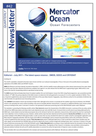
  • 1. #42 Editorial – July 2011 – The latest space mission : SMOS, GOCE and CRYOSAT GreeƟngs all, This month’s newsleƩer is devoted to the latest space mission and their use in physical oceasnography. A focus is here put on the possible physical oceanography applicaƟons of the SMOS, GOCE and CRYOSAT missions. SMOS (Soil Moisture and Ocean Salinity), launched on November 2, 2009, is the first satellite mission addressing sea surface salinity measurements from space. Realis- Ɵc salinity maps have been obtained and preliminary validaƟon tests against in situ data indicate that the SMOS team is approaching its goals. SMOS will be a mile- stone in the route for incorporaƟng salinity to operaƟonal remote sensing. The GOCE (Gravity Field and Steady-State Ocean CirculaƟon) satellite, first core Earth Explorer mission from ESA’s Living Planet programme, was successfully launched on March, 17th 2009. One primary objecƟve of the GOCE mission is to determine the Earth geoid with an accuracy of 1-2 cm for a spaƟal resoluƟon of 100 km. This is an important supplementary step towards the beƩer esƟmaƟon of the ocean Mean Dynamic Topography, a key reference surface for the assimilaƟon of alƟmetric Sea Level Anomalies into operaƟonal ocean forecasƟng systems. ESA's CRYOSAT Earth Explorer mission was launched on 8 April 2010. Although its first mission is to provide the first satellite maps of sea-ice thickness, the CRYOSAT mission is also operaƟng over ocean surfaces providing a new source of valuable alƟmeter measurements. It represents an addiƟonal alƟmeter ocean mission comple- mentary to exisƟng Envisat, Jason-1 and Jason-2 missions in the operaƟonal mulƟmission processing chain of the SSALTO/DUACS system used in MyOcean. The newsleƩer is presenƟng the following scienƟfic arƟcles: First, Font et al. present the characterisƟcs of the SMOS instrument, a summary of the sea surface salinity retrieval from SMOS observaƟons and shows iniƟal results obtained one year and a half aŌer launch. At present there are sƟll several issues being addressed by the SMOS team, mainly related to low level data processing but also to the retrieval of salinity from radiometric measurements, which prevent by now from reaching the mission objecƟves in terms of salinity accuracy. However, realisƟc salinity maps have been obtained and will be presented. Second, Rio and Mulet carry out an inde- pendent validaƟon of the different GOCE geoid models, in order to assess their accuracy and determine which one is beƩer suited for oceanographic applicaƟons and Mean Dynamic Topography esƟmaƟon. Both the impact of the different methodologies used to compute the gravity fields as well as the contribuƟon of the four months of supplementary data have been checked. Third, Dorendeu et al. present a dedicated experiment in order to esƟmate to which extent valuable ocean alƟ- metric signals can be extracted from CRYOSAT data and how this opportunity mission could be merged with exisƟng Envisat, Jason-1 and Jason-2 missions in the oper- aƟonal mulƟmission processing chain of the SSALTO/DUACS system. Finally, Meinvielle et al. are wriƟng on how to opƟmally improve the atmospheric forcing of long term global Ocean simulaƟons with Sea Surface Temperature (SST) observaƟons. The objecƟve of their research is to develop a new assimilaƟon scheme based on advanced staƟsƟcal methods that will use SST satellite observaƟons to constrain the surface forcing funcƟon of long term ocean circulaƟon simulaƟons. The next October 2011 issue will be dedicated to the reanalysis and reprocessing products within MyOcean. We wish you a pleasant reading! Newsletter QUARTERLY (leŌ panel) ArƟst’s view of SMOS in orbit with its Y-shaped antenna array (right panel) Global map of surface salinity (psu) generated from 10 days of SMOS measurements in August 2010. Credits: Font et al. this issue.
  • 2. Quarterly Newsletter Mercator Ocean CONTENT SMOS: AN EARTH EXPLORER MISSION TO OBSERVE OCEAN SALINITY WITH A NOVEL TECHNOLOGY By Jordi Font, Jacqueline Boutin, Nicolas Reul, Paul Spurgeon, Steven Delwart and the SMOS Ocean Salinity Team AN OCEANOGRAPHIC ASSESSMENT OF THE PRELIMINARY GOCE GEOID MODELS ACCURACY By Marie-Hélène Rio and Sandrine Mulet CRYOSAT2 : AN OPPORTUNITY MISSION FOR MYOCEAN AND OCEANOGRAPHY—FROM THEORY TO PRACTICE By Joel Dorandeu, Gerald Dibarboure, Sylvie Labroue, Cécile Renaudie, Nicolas Picot, Tommaso Parrinello OPTIMALLY IMPROVING THE ATMOSPHERIC FORCING OF LONG-TERM GLOBAL OCEAN SIMULATIONS WITH SEA-SURFACE TEMPERATURE OBSERVATIONS By Marion Meinvielle, Pierre Brasseur, Jean-Michel Brankart, Bernard Barnier, Thierry Penduff, Jean-Marc Molines 3 12 20 24
  • 3. #42—July 2011—3Mercator Ocean Quarterly Newsletter SMOS: AN EARTH EXPLORER MISSION TO OBSERVE OCEAN SALINITY WITH A NOVEL TECHNOLOGY By Jordi Font(1) , Jacqueline Boutin(2) , Nicolas Reul(3) , Paul Spurgeon(4) , Steven Delwart(5) and the SMOS Ocean Salinity Team 1 Institut de Ciències del Mar CSIC / SMOS Barcelona Expert Centre, Barcelona, Spain 2 Laboratoire d’Océanographie et du Climat-Expérimentation et Approches Numériques / Institut Pierre Simon Laplace – UMR 7159 CNRS/IRD/ UPMC/MNHN, Paris, France 3 Laboratoire d'Océanographie Spatiale, Institut Français de Recherche pour l'Exploitation de la Mer, Plouzané, France 4 ARGANS Ltd, Plymouth, England, UK 5 ESRIN – European Space Agency, Frascati, Italy Abstract SMOS (Soil Moisture and Ocean Salinity), launched on November 2, 2009, is the first satellite mission addressing sea surface salinity measure- ments from space. Its unique payload is MIRAS (Microwave Imaging Radiometer using Aperture Synthesis), a new two-dimensional interferome- ter designed by the European Space Agency (ESA) and operating at the microwave L-band. This paper presents the characteristics of the instru- ment, a summary of the sea surface salinity retrieval from SMOS observations and shows initial results obtained one year and a half after launch. The pioneer nature of this mission, both from the technological and data processing points of view, implies many challenges that require continu- ous improvements even the mission was declared operational in May 2010. At present there are still several issues being addressed by the SMOS team, mainly related to low level data processing but also to the retrieval of salinity from radiometric measurements, which prevent by now from reaching the mission objectives in terms of salinity accuracy. However, realistic salinity maps have been obtained and preliminary validation tests against in situ data indicate we are approaching our goals. SMOS will be a milestone in the route for incorporating salinity to operational remote sensing. Introduction On November 2, 2009 the European Space Agency successfully launched from northern Russia the first of its Earth Explorer Opportunity Mis- sions (EEOM): SMOS, Soil Moisture and Ocean Salinity (Kerr et al., 2001). These are small format missions aimed at demonstrating new technol- ogies to provide relevant new information for Earth observation from space, and are proposed to ESA by the scientific community through dedicat- ed calls. The opportunity missions are complementing the Earth Explorer Core Missions (the first one being the Gravity field and steady-state Figure 1: Artist’s view of SMOS in orbit with its Y-shaped antenna array SMOS: an earth explorer mission to observe ocean salinity with a novel technology
  • 4. #42—July 2011—4Mercator Ocean Quarterly Newsletter Ocean Circulation Explorer, GOCE, launched in March 2009) designed and implemented by ESA as part of the science and research component of its Living Planet Programme. SMOS was submitted to the first EEOM call in 1998, and selected for a feasibility study, and later detailed design and implementation, under the format of an ESA-lead mission in cooperation with France (CNES) and Spain (CDTI); Yann Kerr (CESBIO, Toulouse) and Jordi Font (ICM-CSIC, Barcelona) were appointed Lead Investigators for soil moisture and ocean salinity, respectively. After launch, an In Orbit Commissioning Phase took place for six months and in May 2010 the mission was declared operational. However, due to the exploratory nature of the mission and the pioneer payload and geophysical retrieval approach used, the algorithms at all levels are continuously being improved and general reprocessing campaigns are envisaged to generate optimised products for the community of users. SMOS, also known as the ESA’s water mission, is expected to be a fundamental step for the future operational provision of these two variables that play a key role in the Earth water cycle (http://www.esa.int/esaLP/LPsmos.html). Figure 1 is an artist’s view of SMOS in orbit with the three antenna arms and solar panels deployed. MIRAS in SMOS: a new technology The remote sensing of ocean salinity and soil moisture is based on a common feature of both geophysical variables: they modify the dielectric properties of respectively seawater and soil. All bodies spontaneously emit electromagnetic radiation in a large range of wavelengths. At low fre- quencies, including microwaves, the brightness temperature of the body (TB, the quantity to be measured by a radiometer, and related to the emit- ted power) is proportional to its physical temperature. The proportionality coefficient, the emissivity, is a function, among other variables, of the dielectric constant and as a consequence of the conductivity, and hence salinity when the emitting body is seawater (see e.g. Lagerloef and Font 2010). SMOS was proposed to measure TB with a microwave radiometer to determine from it sea surface salinity (SSS) over the oceans and soil moisture over land surfaces. The SMOS radiometer operates at 1.413 GHz (within L-band), close to the maximum sensitivity of TB to changes in salinity and soil moisture and where the impact of other parameters influencing it is minimal. [1.400-1.427] GHz is a frequency band where human made emissions are banned by international regulations since it is kept for passive observations. The principles of SSS and soil moisture determination by microwave radiome- try were sufficiently known for decades, but no satellite mission had attempted so far to measure these variables due to the very large scanning antennas required to obtain a reasonable spatial resolution (few tens of km) at this frequency. In order to overcome this problem SMOS is using a large number of small antennas (20 cm diameter), deployed along three 4 m arms forming a Y shape. This is the same principle used in radioastronomy for more than 50 years to achieve a very large synthetic antenna from an array of anten- nas distributed on ground. This instrumental design, known as MIRAS (Microwave Imaging Radiometer using Aperture Synthesis), is the result of an innovative technological concept developed by ESA (McMullan et al., 2008) through the implementation in two dimensions of synthetic aper- Figure 2: MIRAS, the SMOS two-dimensional inter- ferometric microwave radiometer, being assembled at EADS CASA Espacio, Madrid SMOS: an earth explorer mission to observe ocean salinity with a novel technology
  • 5. #42—July 2011—5Mercator Ocean Quarterly Newsletter ture radiometry, first proposed for Earth observation by LeVine and Good (1983) and Ruf et al. (1988) as a way to increase the angular resolution of individual antennas. MIRAS (figure 2) is the first ever interferometric radiometer onboard a satellite. Cross-correlations between the signals collected by all pairs of 69 small antennas are measured every 1.2 seconds. After a process of internal and external calibration, these correlations, together with the average TB measured at low spatial resolution by three dedicated radiometers on board, become the so-called complex visibility, a two-dimensional func- tion of the relative distance between antennas in each pair. In a first-order approximation, the source TB image, as a function of the spatial direc- tions, is equal to the two-dimensional Fourier transform of this visibility function (Corbella et al. 2004). The image is then retrieved from the cali- brated visibility by using a suitable inversion algorithm. In the end, this can be shown to be equivalent to synthesizing a narrow antenna beam at each spatial direction or pixel. The principal advantage of this technique is that, unlike a classical total power radiometer, it does not require any mechanical scanning to achieve a complete map of brightness temperature: One full image snapshot is obtained at a time every 1.2 seconds in the case of SMOS. On the other hand, the image has multiple incidence angles, mixed polarisation and different radiometric quality (sensitivity and resolution) depending on the spatial direction. The development and manufacturing of MIRAS has been a large technological challenge. Besides the innovative instrumental concept itself, it includes many state-of-the-art subsystems and some of them (for example the optical harness) provide solutions that have been implemented in space for the first time. Up to now, after more than one year and a half from launching, it continues to operate successfully with all parameters within their expected range of variation. Details on MIRAS and interferometric polarimetric radiometry can be found in Font et al. (2010), together with abundant bibliographic references. Determining salinity from SMOS measurements SMOS is orbiting at 755 km, has a repeat cycle of 144 days (almost repeat in 18 days), and the antenna plane is tilted 32.5º from horizontal. This way the spatial coverage is maximised and any point on Earth is sampled at least once every 3 days, a requirement for soil moisture observations (Waldteufel et al., 2003). The reconstructed SMOS TB images are curved hexagons, almost 1000 km wide, formed by pixels from 30 to 100 km, with varying incidence angle and radiometric resolution depending on their location with respect to the antenna boresight in each snapshot. At each SMOS overpass salinity is determined by comparing, for any single spot at the ocean surface, the measured TB at different incidence angles while the spot is inside the field of view in successive satellite snapshots, to the TB theoretically emitted by the ocean at the corresponding angles. The latter is computed by a forward model of the ocean emission taking into account the actual seawater conditions. A cost function is minimised in a convergence loop, where the value of SSS is corrected from a first guess until an optimal fit with the measured TB is reached. The relationship between temperature, salinity, angle of observation, frequency and the radiation polarisation state with the microwave brightness temperature is given, from basic principles, only for a flat-sea condition. The effect of the sea roughness upon TB, the main source of geophysical error in salinity remote sensing (Yueh et al. 2001), is taken into account as a correction to the flat-sea value. Information on roughness is derived from operational forecasts of wind and wave characteristics from the European Centre for Medium-range Weather Forecast that also provides other auxiliary information required as sea surface temperature or atmospheric parameters. Moreover, further corrections must be made consider- ing that the emitted radiation is modified in its path from the surface to the satellite (attenuation by the atmosphere, polarisation mixing in the iono- Figure 3: Salinity retrieval approach with SMOS. (left panel) Different sources of L-band radiation that can reach the radiometer; (right panel) Block diagram of the SMOS salinity processor, from filtering degraded measurements to recovering three different salinity values using three alternative roughness correction models. SMOS: an earth explorer mission to observe ocean salinity with a novel technology
  • 6. #42—July 2011—6Mercator Ocean Quarterly Newsletter sphere, …), and other sources of radiation at the same frequency may exist that can also reach the radiometer (emission by the atmosphere, galactic radiation scattered on the surface, …). The result is a quite complex algorithm implemented in the SMOS salinity processor (Zine et al. 2008) that includes a series of sequential modules (figure 3), from filtering out erroneous or low quality TB and auxiliary data, to models of all the involved physical processes, and to the SSS retrieval scheme and generation of the SMOS salinity product. This output product, known as level 2 (geophysical variable, in this case retrieved salinity, in a per orbit basis), is distributed by ESA as strips over ocean areas centered along the satel- lite subtrack. The multiangular measurement characteristics of SMOS should allow for a redundant determination of SSS. However, it was estimated during the mission development that radiometric noise and other possible errors (mainly due to the instrument performance limitations, image reconstruction process, errors on auxiliary parameters, and incomplete forward model formulation) would result in accuracy in retrieved SSS of the order of 1-2 salinity units. The high level of noise in single orbit SSS determinations should be reduced by spatial and temporal averaging, that is generating salinity maps from the level 2 products. The integration of several SMOS orbits in a temporal window of 10-30 days and spatial resolution of 100- 200 km can provide a product similar to present climatologies but including the temporal evolution. The goal is to achieve salinity accuracy of the order of 0.1 salinity units, which is relevant to the study of large scale oceanographic and climatic phenomena, like the observation and forecast of El Niño events, the North Atlantic thermohaline circulation, or the estimation of open ocean precipitation (Font et al., 2004). The ESA mandate for SMOS is to design, implement, launch, and operate the mission during its entire life (nominal 3 years, expected 5 years and even beyond), and to deliver products to users up to level 2, as well as maintaining a long-term archive. A near-real time processing chain has also been set up following the demand of operational meteorological institutions, like ECMWF or the Meteorological Service of Canada. Both cen- tres are now monitoring and plan to assimilate soon SMOS level 1 (brightness temperature) data over land into their numerical weather systems. In order to generate higher level products, both France and Spain committed to design, fund, implement and operate additional SMOS data pro- cessing centers. While these additional products are, in a first stage, global gridded maps (level 3), later products will be proposed through the integration of the SMOS data with other sources of information (level 4), both from Earth observation satellites, as the US-Argentina Aquarius salinity mission (Lagerloef et al. 2008) launched on 10 June 2011, and from in situ measurement systems. The French Centre Aval de Traitement de Données SMOS (CATDS) is installed in the Institut français de recherche pour l’exploitation de la mer (IFREMER, Brest), while the Spanish Centro de Proceso de datos SMOS de niveles 3 y 4 (CP34) is operating in the European Space Astronomy Centre (ESAC, near Madrid) next to the official ESA SMOS Data Processing Ground Segment. First results and remaining issues Soon after MIRAS switching-on and first calibrations, level 1 data (TB) were available from December 2009 onwards and the characteristics of the reconstructed images field and their impact on the level processing could be examined. As explained before, MIRAS is performing according to the specified requirements, or even better. Measured radiometric sensitivity over the oceans is in agreement with theory, thermal noise is negligi- ble after calibration, and the instrument appears to be reasonably stable over several months. Therefore, from an instrumental point of view, the TB images are currently generated operationally with good quality. However, corrections applied to the routine radiometer calibrations and some aspects of image reconstruction procedures still need to be refined for an optimal SSS product, while some components of the forward model, Figure 4: The strong salinity (psu) gradient of the Amazon plume measured by SMOS in August 2010 SMOS: an earth explorer mission to observe ocean salinity with a novel technology
  • 7. #42—July 2011—7Mercator Ocean Quarterly Newsletter mainly the roughness correction module (designed before launch), are being improved through analysis of real SMOS data. Nevertheless, the first salinity retrieval tests performed by the SMOS L2OS (L2 Ocean Salinity) processor showed meaningful geophysical signals, such as the expected latitudinal salinity variation along an ascending orbit in the Pacific Ocean and the strong gradients associated to the Amazon plume (figure 4). Figure 5 shows the first satellite salinity map generated in early February 2010 by combining ten SMOS ascending orbits acquired in late January in the Pacific without data filtering or averaging. This SSS field was retrieved using a simplified algorithm instead of the full L2OS processor, for a first retrieval test from the SMOS level1 products. A comparison of SMOS to the January surface salinity climatology from the World Ocean Atlas 2005 (Antonov et al., 2006) shows a considerable coherence both in terms of spatial structure and absolute values. Degraded results are found near the swath borders, where the number of TB measurements for each grid point is the smallest and where the radiometric quality is poor, and also near the coast. The plot also shows areas of strong winds in high North and South latitudes where roughness correction models seem not to be reliable enough and the sensitivity of TB to SSS is minimal due to low sea surface temperatures. Font et al. (2011) present a summary of the main issues that are now affecting the quality of the SSS retrieved by SMOS. By May 2011 new ver- sions of the level 1 and level 2 processors have been delivered and will be ingested in the processing chain, as well as used in autumn this year for a general reprocessing of all the data from the beginning of the mission. A note for the SMOS swath ocean salinity products users has been prepared by the authors and is being displayed in the ESA web site: “The present OS level 2 processor, which includes the last corrections and improvements as result of the data analysis during and beyond the Commissioning Phase, is ready to deliver the best salinity products available, although still not reaching the expected quality, with several issues under study by the development team. Details on the processing algorithms can be found in the Algorithm Theoretical Baseline Document (ATBD), and on the L2OS products structure in the SMOS Level 2 and Auxiliary Data Products Specifications, both available from ESA (all docu- ments available on www.earth.esa.int/smos). Additional information, including documentation, product thumbnails and FAQs, can also be found on the SMOS L2OS website: www.argans.co.uk/smos. Users should be aware that by now these L2OS products are to be intended more for diagnosing and improving the SMOS salinity retrieval than for their operational use in oceanographic research. The following comments have to be taken into account for a proper understanding, interpretation and assessment of the OS products: The released SMOS salinity products are not yet validated. They are the result of applying the algorithms described in the ATBD that will evolve from the experience gained with several months of data analysis, and from the feedback provided by the SMOS validations teams, which started working in July 2010. A general reprocessing is expected to take place summer 2011 after new corrections and improvements at all levels. Three different salinity values are included for each grid point of the L2OS products. These correspond to the three roughness effect model op- tions included in the retrieval, as described in the ATBD. These models have been tuned and modified to improve retrievals, and will continue to be refined for the 2011 reprocessing. Hopefully in the future a unique optimal salinity value will be delivered. The SMOS L2 OS User Data Product contains many flags and descriptors to help understanding the characteristics and circumstances of the salinity products generation. These are described in the above referenced documents. Missing salinity values are indicated by -999. Since March 2011 a new algorithm for calculating the quality index (Dg_quality_SSS), and new quality flags, have been introduced into the L2OS User Data Product, which may be used to filter grid points, for example where good quality salinity has been retrieved, or where specific geophysical condi- tions may have an impact on retrieval quality: for details see Fg_ctrl_poor_quality and Fg_ctrl_poor_geophysical in the Input/Output Data Defini- tion (http://www.argans.co.uk/smos/docs/deliverables/delivered/IODD/SO-TN-ARG-GS-0009_L2OS-IODD_v2.18_101207.pdf). SMOS salinity retrieval is based on a comparison between measured (L1c products, at antenna level, not surface level) and modeled (ocean sur- face emission including salinity contribution) brightness temperatures. After MIRAS being optimally calibrated, there is still a residual average Figure 5: First SMOS salinity (psu) map obtained by superposing 10 as- cending orbits over the Pacific Ocean in December 2009 (by J. Tenerelli, CLS, Brest) compared to World Ocean Atlas 2005 climatology. SMOS: an earth explorer mission to observe ocean salinity with a novel technology
  • 8. #42—July 2011—8Mercator Ocean Quarterly Newsletter misfit between measured and modeled TB over homogeneous ocean areas probably due to instrumental and image reconstruction method imper- fections. The resulting bias has a persistent spatial pattern as seen in the antenna cosinus-director frame that is now removed in the processor by introducing Ocean Target Transformation Look Up Tables) to the L1 TB before running salinity forward models. This transformation basically con- sists in applying a constant offset (positive or negative) to the TB depending on their coordinates in the antenna frame (incidence and azimuth angles). This step is now described as an appendix in the last version of the ATBD http://www.argans.co.uk/smos/docs/deliverables/delivered/ ATBD/SO-TN-ARG-GS-0007_L2OS-ATBD_v3.6_101207.pdf). Alternative bias removing methods are being tested and may be incorporated in future versions of the L2OS processor. Poorer quality retrieval can be seen near to the edges of each swath, where less TB measurements are available for each grid point and radio- metric quality is poorer. This may be removed in further versions of the processor in case that only Alias-Free data are used, instead of Extended- Alias-Free as implemented now. Anyway, the expected accuracy of the salinity retrieval at L2 is of the order of 1-2 psu depending on the distance to satellite subtrack and other environmental conditions. To reach the 0.1-0.2 salinity units at GODAE scales stated in the SMOS mission objec- tives, further spatio-temporal averaging is needed to reduce the noise level. This is to be done by the French CATDS and Spanish CP34 high level SMOS data processing centres. CP34 is already operational and users can register at http://www.cp34-users.cmima.csic.es/. A problem that can be observed in SMOS TB and salinity data is the contamination from land as soon as land masses enter the SMOS very wide antenna field of view. This depends on the distribution of brightness temperature of the land masses far away from the scene for which SSS is retrieved. This effect impacts the quality of the retrievals in spatial bands following the world continent major coast-lines and spanning over differ- ent distances from coast, depending on the orbit orientation. A similar effect can be observed in ice-sea transition areas. The problem is thought to be an image reconstruction issue and improvements are expected to be introduced in further versions of the L1 processor. Another problem now under study is the impact of antenna temperature in the generated brightness temperatures. Seasonal TB drifts have been observed, as well as differences between ascending and descending passes, and this appears to be due to the different position of the Sun with respect to the antennas. These small drifts (that can reach up to 1 ºK in 6 months in the Extended-Alias-Free Field-of-View) are irrelevant for soil moisture retrieval but not for salinity. New antenna pattern models and calibration corrections are being tested and will be incorporated in further versions of the L1 processors. Although not as dramatic as over land, SMOS ocean images can also be affected by radiofrequency interferences generated by illegal man-made emissions, and this is especially important in some regions as in the Northern Atlantic. This is now under investigation to find efficient methods for ◄ Figure 6: A SMOS level 2 swath product (ascending semi-orbit) generated with the latest versions of the L1 and L2 processors, not yet ingested in the production chain. The image evidences the noisy character of the retrieved salinity (psu) on a single satellite overpass, and the effect of filtering out pixels that have been found to be outliers or too close to land or sea ice. ▲ Figure 7: Global map of surface salinity (psu) generated from 10 days of SMOS measurements in August 2010 reprocessed with the latest version of the level 1 and level 2 processors, including removal of the main land contamination effects and with improved roughness correction. White areas over the ocean indicate that data have been filtered out due to low quality. SMOS: an earth explorer mission to observe ocean salinity with a novel technology
  • 9. #42—July 2011—9Mercator Ocean Quarterly Newsletter identification and removal of contaminated data, as well as in the political/technical side to get the illegal sources being switched-off by the corre- sponding national authorities (many successful actions have been achieved until now). It can also be noticed that salinity retrieval is worse in cold oceans (TB sensitivity to SSS decreases with decreasing SST) and also in areas of strong winds. The three roughness impact models now implemented in the L2OS processor (that generate three different SSS values) are per- forming less well under strong winds. This is also being addressed by the algorithms development teams to find improved formulations, and the L2 algorithm version operational from March 2011 includes new roughness correction algorithms fitted to SMOS data. Significant differences are found between SSS retrieved in ascending and descending passes, particularly at high latitudes. Besides the drift prob- lem mentioned above, this can also be related to sunglint effects. Although a method to flag and correct for sunglint contamination is implemented in the processor, it seems to introduce an artificial bias which is seasonal and latitude dependent in descending passes. This may be a source for the observed differences between passes, as the miss-match is dominant in the descending passes southern latitudes, for which sun glint is the strongest. Other imperfections in these products can be due to image reconstruction problems still to be solved or to the salinity retrieval process, from the forward models to simulate the ocean emission and its fate until reaching the instrument antenna, until the inversion technique. Feedback from the users in identifying problems and proposing solutions will be more than welcome.” Several of the above mentioned issues have been significantly mitigated in the new versions of the processors that will be operational from sum- mer 2011, especially short term drifts linked to variability of the antennas physical temperature and the strong land contamination around the con- tinents that was beyond theoretical expectations (figure 6). Figure 7 is a global salinity map built offline from level 2 products by the SMOS Barce- lona Expert Centre in June 2011 using the latest versions of the processors. As mentioned herein, SMOS is a completely new Earth observation mission, both from the instrument and algorithmic points of view. Therefore, the validation of the products it provides is the fundamental step to demonstrate the feasibility of the proposed approach for future operational missions to regularly provide soil moisture and ocean salinity. The evolving situation, with continuous improvements of the algorithms, will allow soon starting systematic validation activities. Evaluation of SMOS salinity data can be better performed using averaged maps than the much noisi- er single level 2 products distributed by ESA. In exploratory tests the SMOS derived SSS maps have been compared to equivalent products from in situ observations, namely the World Ocean Atlas climatologies and interpolated maps from the Argo array of drifting profiling floats. Figure 8 displays the 10-day averaged SMOS SSS for the period February 6, 2011 through February 16, 2011 computed with the current opera- tional SMOS products (that is before the last land contamination correction, not operational yet) minus surface salinity from WOA 2005 monthly climatology. The activation of the processor error flags masks large portions of the North Atlantic, East Pacific, North Indian Ocean and Mediterra- nean Sea that are regions systematically affected by interferences. The spatial distribution of the surface salinity displays coherent spatial struc- tures of fresh anomalies in the open oceans in the tropical regions. Salty anomalies, too large compared with the known variability of the SSS field, are observed for the Southern ocean and near coastal areas, and are supposed to be mainly due to the above mentioned strong land (and ice) contamination effect. Analyzing for the same period the differences between SMOS and interpolated Argo data 7.5 m deep, we find that SMOS SSS shows globally a bias of 0.3 psu with a standard deviation of 0.8 psu. This is really encouraging, especially taking into account Figure 8: Field of SMOS SSS anoma- ly (psu) with respect to World Ocean Atlas 2005 climatology for the period 6 to 16 February 2011, computed from the level 2 products operational- ly delivered by the SMOS Data Pro- cessing Ground Segment. SMOS: an earth explorer mission to observe ocean salinity with a novel technology
  • 10. #42—July 2011—10Mercator Ocean Quarterly Newsletter (besides that SMOS samples the first cm while Argo provides subsurface information) that the recent processor modifications will allow improving this situation, and that once SMOS level 1 will reach an optimum calibration and image reconstruction quality, there is still room for improvements in the salinity retrieval through better roughness correction formulations. Conclusion Salinity microwave remote sensing has limitations due to the weak TB sensitivity to SSS that requires an excellent accuracy and stability of a radi- ometer. For a fixed incidence angle, the entire range of salinity in the world oceans corresponds to about 5 ºK in TB, while this is up to 100 ºK for the soil moisture range. SMOS is the first attempt to obtain this information from space with a novel technology, L-band interferometric radiometry, never used before onboard a satellite. After one year of regular operations, the SMOS MIRAS instrument has demonstrated to comply with the strict technical requirements and deliver the planned radiometric information. The complexity of the image reconstruction process that integrates large area total power measurements with high angular resolution demands a very accurate low level data processing, still being refined. The pioneer geophysical modeling, plus additional problems like the impact of illegal man-made emissions within the forbidden band or the effect of external natural radiation (e.g. galactic noise) reaching the radiometer through scattering on the ocean surface, is also a real challenge. However, we have been able to obtain realistic salinity retrievals and are significantly advancing into the generation of products useful for large scale ocean- ographic studies, even the mission requirements may not be reached in some specific ocean areas. We expect demonstrating this is an adequate approach for future missions to regularly deliver SSS information to complement the existing in situ observing systems (Lagerloef et al., 2011) and hence improving our present capability to diagnose and forecast the state of the world oceans. Acknowledgements The design, implementation and operation of SMOS has been possible thanks to the effort of many scientific, technological and industrial Europe- an teams for almost twenty years. The SMOS level 2 processor development was funded by ESA under different contracts. This work was also supported in part by the French Centre National d’Etudes Spatiales, and by the Spanish National R+D Plan for the SMOS Barcelona Expert Cen- ter on Radiometric Calibration and Ocean Salinity (http://www.smos-bec.icm.csic.es) activities, through project AYA2010-22062-C05 and previous grants. References Corbella, I., Duffo N., Vall-llossera, M., Camps, A. and Torres, F. 2004: The visibility function in interferometric aperture synthesis radiometry. IEEE T. Geosci. Remote 42:1677–1682. Font, J., Lagerloef, G.S.E., Le Vine, D.M., Camps, A. and Zanifé, O.Z. 2004: The determination of surface salinity with the European SMOS space mission. IEEE T. Geosci. Remote 42:2196-2205. Font,, J., Camps, A., Borges, A., Martín-Neira, M., Boutin, J., Reu,l N., Kerr, Y.H., Hahne, A. and Mecklenburg, S. 2010: SMOS: The challenging measurement of sea surface salinity from space. P. IEEE 98:649-665. Font, J., Boutin, J., Reul, N., Spurgeon, P., Ballabrera-Poy, J., Chuprin, A., Gabarró, C., Gourrion, J., Hénocq, C., Lavender, S., Martin, N., Mar- tínez, J., McCulloch, M., Meirold-Mautner, I., Mugérin, C., Petitcolin, F., Portabella, M., Sabia, R., Talone, M., Tenerelli, J., Turiel, A., Vergely, J.L., Waldteufel, P., Yin, X., Zine, S. and Delwart, S. 2011:. SMOS first data analysis for sea surface salinity determination. Int. J. Rem. Sens. (in press). Kerr, Y.H., Waldteufel, P., Wigneron, J.P., Martinuzzi, J.M., Font, J. and Berger M. 2001: Soil moisture from space: the Soil Moisture and Ocean Salinity (SMOS) mission. IEEE T. Geosci. Remote 39:1729-1735. Lagerloef, G.S.E., Colomb, F.R., Le Vine, D.M., Wentz, F., Yueh, S.H., Ruf, C., Lilly, J., Gunn, J., Chao, Y., deCharon, A., Feldman, G. and Swift, C.T. 2008: The Aquarius/SAC-D mission designed to meet the salinity remote sensing challenge. Oceanography 21:68-81. Lagerloef, G.S.E. and Font, J. 2010: SMOS and Aquarius/SAC-D missions: The era of spaceborne salinity measurements is about to begin. In: V. Barale, J.F.R. Gower, L. Alberotanza (eds.), Oceanography from Space. Springer Science+Business Media B.V., pp. 35-58. Lagerloef, G.S.E., Boutin, J,. Chao, Y., Delcroix, T., Font, J., Niiler, N., Reul, N., Schmitt, R., Riser, S., Stammer, D. and Wentz, F. 2011: Resolv- ing the global surface salinity field and variations by integrating satellite and in situ observations. In: Hall J., Harrison D.E., Stammer D. (eds.), Proceedings of OceanObs'09: Sustained Ocean Observations and Information for Society (Vol. 2), ESA Publication WPP-306 (in press) SMOS: an earth explorer mission to observe ocean salinity with a novel technology
  • 11. #42—July 2011—11Mercator Ocean Quarterly Newsletter LeVine, D.M. and Good, J.C. 1983: Aperture synthesis for microwave radiometers in space. NASA Technical memorandum 85033. McMullan, K., Brown, M., Martín-Neira, M., Rits, W., Ekholm, S., Marti, J. and Lemanzyk, J. 2008: SMOS: The payload. IEEE T. Geosci. Remote 46:594-605. Ruf, C.S., Swift, C.T., Tanner, A.B. and Le Vine, D.M. 1988: Interferometric synthetic aperture microwave radiometry for the remote sensing of the Earth. IEEE T. Geosci. Remote 26:597-611. Waldteufel, P., Boutin, J. and Kerr, Y.H. 2003: Selecting an optimal configuration for the Soil Moisture and Ocean Salinity mission. Radio Sci. 38:8051. Antonov, J.I., Locarnini, R.A., Boyer, T.P., Mishonov, A.V. and Garcia, H.E. 2006: World Ocean Atlas 2005, Volume 2: Salinity, S. Levitus ed., NOAA Atlas NESDIS 62, U.S. Government Printing Office, Washington, D.C. 182 pp. Yueh, S.H., West, R., Wilson, W.J., Li, F.K., Njoku, E.G. and Rahmat-Samii, Y. 2001: Error sources and feasibility for microwave remote sensing of ocean surface salinity. IEEE T. Geosci. Remote 39:1049-1060. Zine, S., Boutin, J., Font, J., Reul, N., Waldteufel, P., Gabarró, C., Tenerelli, J., Petitcolin, F., Vergely, J.L., Talone, M. and Delwart, S. 2008: Overview of the SMOS sea surface salinity prototype processor. IEEE T. Geosci. Remote 46:621-645. SMOS: an earth explorer mission to observe ocean salinity with a novel technology
  • 12. #42—July 2011—12Mercator Ocean Quarterly Newsletter AN OCEANOGRAPHIC ASSESSMENT OF THE PRELIMINARY GOCE GEOID MODELS ACCURACY By Marie-Hélène Rio(1) and Sandrine Mulet(1) (1) CLS / Space Oceanography Division, Ramonville Saint-Agne, France INTRODUCTION The GOCE (Gravity Field and Steady-State Ocean Circulation) satellite, first core Earth Explorer mission from ESA’s Living Planet programme, was successfully launched on March, 17th 2009. One primary objective of the GOCE mission is to determine the Earth geoid with an accuracy of 1 -2 cm for a spatial resolution of 100 km. After the success of the GRACE mission (launched in March 2005, and still operating), which exploitation has allowed to improve the geoid knowledge at scales greater than 300km, this is an important supplementary step towards the better estimation of the ocean Mean Dynamic Topography, a key reference surface for the assimilation of altimetric Sea Level Anomalies into operational ocean forecasting systems. Two years after launch, six preliminary GOCE geoid models have been made available, based on three different computational approaches. For each approach, two releases have been made, the first one in June 2010, based on 2 months of GOCE data, and the second one in March 2011, based on more than 6 months of data. In this study, an independent validation of the different GOCE geoid models has been carried out in order to assess their accuracy and determine which one is better suited for oceanographic applications, if any. Both the impact of the different methodologies used to compute the gravity field as well as the contribution of the four months of supplementary data have been checked. Section 2 gives more details about the different GOCE geoid models available. The assessment method developed to assess the accuracy of the different solutions is presented in section 3 and the results are analyzed in section 4. Section 5 gives the main conclusions and perspectives of this study. GOCE data The ESA HPF (High Processing Facility) has used three different approaches to compute the GOCE geoid models (Pail et al, 2011). The time- wise (Pail et al, 2010) and the space-wise (Migliaccio et al, 2010) approaches have been especially developed for the GOCE mission while the direct approach (Bruinsma et al, 2010) is more classical. Two releases computed from respectively 2 months and 6 months of GOCE data are available for each geoid models based on the time-wise and the direct approaches. Only one release based on the space-wise approach is availa- ble and uses 2 months of GOCE data. The two releases based on the direct approach (EGM_DIR_R1 and EGM_DIR_R2) are developed to order and degree 240 of spherical harmon- ics (83 km resolution). EGM_DIR_R1 results from 2 months of GOCE data constrained toward Eigen_51C that combines surface and GRACE data (Bruinsma et al, 2010) while EGM_DIR_R2 results from 6 months of GOCE data constrained toward ITG_Grace2010s that is a GRACE (Gravity Recovery And Climate Experiment) only solution (Kurtenbach et al, 2009). The first release based on the time-wise approach (EGM_TIM_R1) is developed to order and degree 224 of spherical harmonics (89 km resolution) while the second release (EGM_TIM_R2) is de- veloped to order and degree 250 (80 km resolution). EGM_SPW is based on the space-wise approach and is developed to order and degree 210 of spherical harmonics (95 km resolution). METHOD In order to investigate the quality of the new GOCE geoid models we have first computed MDTs from EGM_DIR, EGM_SPW and EGM_TIM. To quantify the improvement of GOCE relative to GRACE mission we have also computed MDT from ITG-Grace2010s developed to order and de- gree 180 and using seven years of GRACE data (Kurtenbach et al, 2009). The MDTs are computed by subtracting the different geoid models from an altimetric Mean Sea Surface. The Mean Sea Surface (MSS) used in this study is the MSS_CNES_CLS10 estimated for the 1993-1999 period (Schaeffer et al, 2010). The MSS resolves spatial scales as short as 10- 20 km while the geoid models are developed up to degree and order 210-250 (i.e. 95-80 km resolution) for the GOCE solutions and up to degree An oceanographic assessment of the preliminary GOCE geoid models accuracy
  • 13. #42—July 2011—13Mercator Ocean Quarterly Newsletter and order 180 (i.e. 111 km resolution) for the GRACE solution. Further filtering is hence needed. We applied a gaussian filter using for the resolu- tion scales six different values (100, 125, 150, 200, 250 and 350 km). In this study, we have mainly focused on the geostrophic currents deduced from the MDTs that are an estimation of the MDT gradients and thus are more sensible to noise than the MDT itself. Moreover it is more convenient to have a reliable estimate of geostrophic currents from in-situ data than an estimate of height above geoid. The estimate of the mean geostrophic currents (called ‘synthetic’ currents in the following) is deduced from all the 15 meter drogued drifting buoy data collected from 1993 to 2008 in the framework of the international WOCE and TOGA Surface Ve- locity Program. These data are distributed by AOML where they first have been quality controlled and krigged (Hansen and Poulain, 1996) in or- der to provide 6-hourly velocity measurements. In order to extract from the drifting buoy velocities only the geostrophic component, the Ekman current was first modelled (Rio and Hernandez, 2003) and substracted. Then, a 3 day low pass filter was applied to the velocities to remove iner- tial and tidal currents as well as residual high frequency ageostrophic currents. Finally the geostrophic velocity anomalies deduced from the Sea Level Anomalies relative to the 1993-1999 period are interpolated along the drifter’s trajectories and subtracted from the associated instantaneous geostrophic currents to have an estimate of the mean geostrophic currents relative to the same 7 year period. The altimetric SLAs used in this study are computed by the SSALTO/DUACS centre and distributed by AVISO (SSALTO/DUACS User Handbook, 2006). The synthetic currents obtained as described above are then filtered at the same resolution scales and using the same Gaussian filter than the MDTs computed from geoid models. Standard deviations of the differences between the geostrophic currents associated with MDTs computed from geoid models and synthetic geo- strophic currents deduced from independent observations are computed at different resolution scales. The results will be discussed in the follow- ing sections. IMPROVEMENT OF GOCE OVER GRACE Figure 1 shows, at different resolution scales, the standard deviation of the difference between synthetic geostrophic current and geostrophic velocities estimated from GRACE and GOCE MDTs. In this part, only the first releases of the GOCE geoid models computed with 2 months of data are used. At scales smaller than 200 km, the standard deviations of the difference are much smaller with MDTs computed with GOCE geoid models (blue lines) than with GRACE geoid model (pink lines). At 100km, GOCE improves a lot the comparisons to independent observations; the gain of EGM_TIM_R1 compared with ITG_Grace2010s is 72% for the zonal velocities and 68% for the meridional velocities. In the Gulf Stream area (Figure 2) the circulation is well described by MDTs computed with GOCE data while MDT computed with         − − − 2 2010 2 _ 2 2010 sGraceITG TIMEGMsGraceITG σ σσ Figure 1: Standard deviation (cm/s) over the global ocean of the difference between the synthetic geo- strophic currents and geostrophic currents associated with MDTs computed from (pink circles) ITG_GRACE2010s, (blue squares) EGM_TIM_R1, (blue diamonds) EGM_SPW_R1 and (blue stars) EGM_DIR_R1. The top plot (resp. bottom) shows results for the zonal (resp. meridional) component. The red dash line shows the standard deviation of the synthetic estimate of the mean geostrophic velocities. An oceanographic assessment of the preliminary GOCE geoid models accuracy
  • 14. #42—July 2011—14Mercator Ocean Quarterly Newsletter ITG_Grace2010s is very noisy. At 150 km GOCE geoid models give standard deviations of the difference (Figure 1) smaller by more than 1.5cm/s than ITG_Grace2010s and smaller than the synthetic variability itself (red dash lines) for both components. At these scales, only 2 months of GOCE data improve a lot the mean oceanic circulation compared with 7 years of GRACE data. At scales larger than 200km, the difference between geoid heights estimated from GRACE data and GOCE data are less than 1.5 cm. Thus, it is difficult to see this difference studying MDTs. At theses scales GOCE and GRACE have similar performances for the computation of Mean Dy- namic Topography. Figure 2 :Intensity of the mean geo- strophic currents (cm/s) in the Gulf Stream area from the 100km-filtered MDTs computed from (a) ITG- GRACE2010s, (b) EGM_SPW_R1, (c) EGM_DIR_R1 and (d) EGM_TIM_R1 Figure 3 : Standard deviation (cm/s) over the global ocean of the difference between the synthetic currents and currents associated with MDTs computed from (blue squares) EGM_TIM_R1 and (green squares) EGM_TIM_R2. The red dash line shows the standard deviation of the synthetic currents. An oceanographic assessment of the preliminary GOCE geoid models accuracy
  • 15. #42—July 2011—15Mercator Ocean Quarterly Newsletter IMPACT OF MORE GOCE DATA In this part we will compare the first HPF releases computed with 2 months of GOCE data and the second HPF releases computed with 3 times more GOCE data. First, the comparison between the first and the second releases of EGM_TIM permit to quantify the impact of using more GOCE data in a GOCE Figure 4 : Mean Dynamic Topography (cm) filtered at 100 km and computed from (a) EGM_TIM_R1 and (b) EGM_TIM_R2. Figure 5 : Intensity of the mean geo- strophic currents (cm/s) in the Kuroshio area from the 100km-filtered MDTs com- puted from (a) EGM_TIM_R2, (b) EGM_TIM_R1, (c) EGM_DIR_R2 and (d) EGM_DIR_R1. An oceanographic assessment of the preliminary GOCE geoid models accuracy
  • 16. #42—July 2011—16Mercator Ocean Quarterly Newsletter only geoid model. Figure 3 shows that using 3 times more GOCE data improve a lot the comparison to independent observations. At 100km, the standard deviation of the difference for the zonal (resp. meridional) velocities decreases by about 2 cm/s (resp. 2.5 cm/s) with EGM_TIM_R2 com- pared with EGM_TIM_R1, the gain is 36 % (resp. 46 %). Figure 4b illustrates the improvement. The MDT computed with the second release of EGM_TIM is globally less noisy than the first release (Figure 4a); the improvement is especially visible in the interior and east of the subtropical gyres and south of Australia. Figure 5a and Figure 5c show the improvement in the Kuroshio area. Then, Figure 6 shows results of the comparison to independent observations for the different geoid models using the direct approach. EGM_DIR_R1 and R2 are both constrained toward an apriori geoid model but not the same. EGM_DIR_R1 is constrained toward Eigen_51C that combines surface and GRACE data while EGM_DIR_R2 is constrained toward ITG_Grace2010s (GRACE only solution). To quantify the impact of more GOCE data, we should compare EGM_DIR_R1 (blue stars on Figure 6) and exactly the same model but with more GOCE data (yellow stars on Figure 6). The improvement is less significant than for the time-wise approach (about 1cm at 100 km) because the surface data including in Eigen_51C give already information about small scales. However, the comparison between the two releases of EGM_DIR is very interesting and permits to quantify the impact of GOCE data in a geoid model that include surface data. At 100km, EGM_DIR_R1 gives better results than EGM_DIR_R2 thanks to the surface data. Figure 5c and Figure 5d illustrate that EGM_DIR_R2 is noisier than EGM_DIR_R1 in the Kuroshio area at 100 km resolution scale. But between 120 and 200 km, EGM_DIR_R2 is slightly better (Figure 6). Thus, GOCE improves mostly scales be- tween 120 and 200 km compared with model that combines surface and GRACE data. COMPARISON BETWEEN THE DIFFERENT APPROACHES In this section, we investigate the influence of the different approaches (time-wise, space-wise and the direct one) in the computation of the mean oceanic circulation. The blue lines on Figure 1 show the results of the comparison to independent observations for the different approaches used in the first HPF re- leases. EGM_DIR_R1 is constrained toward Eigen51C, a geoid model that combines GRACE and surface data. The surface data help to improve small scales compared with the satellite only geoid models. Thus, it is not surprising that the direct approach gives smaller standard deviations of the difference than the other approaches. EGM_SPW_R1 and EGM_TIM_R1 give almost similar results, the space-wise approach give slightly Figure 6 : Standard deviation (cm/s) over the global ocean of the difference between the synthetic estimate of mean geostrophic velocities and geo- strophic currents associated with MDTs computed from (blue stars) EGM_DIR_R1, (green stars) EGM_DIR_R2 and (yellow stars) a geoid model equivalent to EGM_DIR_R1 but with 6 months of GOCE data. The top plot (resp. bottom) shows results for the zonal (resp. me- ridional) component. The red dash line shows the standard deviation of the synthetic estimate of the mean geo- strophic velocities. Figure 7 : Intensity of the mean geostrophic currents (cm/s) in the New Zealand area from the 150km-filtered MDTs computed from (a) EGM_SPW_R1 and (b) EGM_TIM_R1. An oceanographic assessment of the preliminary GOCE geoid models accuracy
  • 17. #42—July 2011—17Mercator Ocean Quarterly Newsletter smaller standard deviations. Figure 7 illustrates that the space-wise approach is a bit noisier than the time-wise approach in the North-East of New Zealand. In this area, the high gravity gradients on the boundary between the Pacific and the Indo-Australian Plates are hardly resolved in the geoid models. On the contrary the Mean Sea Surface has higher resolution and resolves these kinds of structures. Thus, the high gravity gradi- ents introduce artifacts in the MDT computed by subtracting the MSS and the geoid height. Figure 8 : Standard deviation (cm/s) over the global ocean of the difference between the synthetic geo- strophic currents and geostrophic currents associated with MDTs computed from (green squares) EGM_TIM_R2 and (green stars) EGM_DIR_R2 .The top plot (resp. bottom) shows results for the zonal (resp. meridional) component. The red dash line shows the standard deviation of the synthetic estimate of the mean geostrophic velocities. cm/s Figure 9 : Root Mean Square differences (cm/s) of zonal (top) and meridional (middle) synthetic velocities computed by 60°by 30°boxes for the EGM-TIM-R2 (left) and the EGM-DIR-R2 (right) solutions. The bottom plot shows for each box which geoid model gives the best comparison to observations (light blue: the EGM-TIM-R2, light green: the EGM-DIR-R2, yellow: the EGM -SPW-R1 , dark blue: the EGM -TIM-R1) An oceanographic assessment of the preliminary GOCE geoid models accuracy
  • 18. #42—July 2011—18Mercator Ocean Quarterly Newsletter On Figure 8, we compare the geoid models from the second HPF releases. EGM_DIR_R2 and EGM_TIM_R2 give globally similar results, with slightly better performance on the meridional component of the velocity for the direct approach. To further investigate the relative accuracy of the- se models and try characterizing regional differences, we have repeated the comparison dividing the global ocean into 60°longitude by 30°lati- tude boxes (Figure 9). Differences are seen depending on the areas. In the Kuroshio area (Figure 5a and Figure 5c) MDT computed with EGM_DIR_R2 is less noisy than the one computed with EGM_TIM_R2. However, it is the contrary south of Australia (Figure 10) where the com- putation of the geoid models is difficult because of the influence of the magnetic pole. The bottom plot of Figure 9 shows for each box which geoid model gives the best comparison to observations. The use of the time-wise approach gives the best results in most parts of the ocean. The space- wise approach shows less agreement to observations than the two other methods. However, only one release is available (based on 2 months of GOCE data). The second release should be made available shortly to update the comparison. CONCLUSIONS The computation of Mean Dynamic Topographies from different geoid models and the comparisons with independent data from in-situ oceano- graphic measurements and altimetry permit to carry out an independent validation of the preliminary GOCE Level-2 products at different resolution scales. Using only 2 months of GOCE data improves the scales smaller than 200 km (DO 100) compared with ITG-Grace2010s, geoid computed with seven years of GRACE data. Using three times more GOCE data also improves the GOCE only geoid models but the improvement is less significant when using a geoid model that combines surface and satellite data. In a combined geoid model, GOCE improves mostly scales be- tween 120 km (DO 166) and 200 km (DO 100). Among the different methods that have been used by the GOCE HPF (High Processing Facility) from ESA, the time-wise approach gives better comparison results to observations in most areas of the ocean. The direct approach gives slightly better results in the Kuroshio current area. A third release of GOCE geoid models will be made available in October 2011, based on almost one year of GOCE data. The accuracy of these new geoids will be tested using the approach described in this paper. Due to the increased number of data, further improvements are already expected for the estimation of the ocean MDT at 100km resolution. For data assimilation into ocean forecasting systems, even higher resolution is needed and the use of GOCE data may be complemented with other independent observations of the ocean mean circulation. For that purpose, combination methods of geodetic MDTs with drifter measure- ments and/or ARGO floats and altimetry (Rio and Hernandez, 2004, Maximenko et al, 2005, Rio et al, 2011) will be required. Figure 10 : Mean Dynamic Topography (cm) fil- tered at 100 km south of Australia computed from (a) EGM_DIR_R2 and (b) EGM_TIM_R2. An oceanographic assessment of the preliminary GOCE geoid models accuracy
  • 19. #42—July 2011—19Mercator Ocean Quarterly Newsletter REFERENCES Bruinsma S.L., Marty J.C., Balmino G., Biancale R., Foerste C., Abrikosov O. and Neumayer H. (2010): GOCE Gravity Field Recovery by Means of the Direct Numerical Method, presented at the ESA Living Planet Symposium, 27th June - 2nd July 2010, Bergen, Norway; See also: earth.esa.int/GOCE Hansen D.V., Poulain P.-M., (1996): Quality Control and Interpolations of WOCE-TOGA Drifter Data. J. Atmos. Oceanic Technol., 13, 900–909. Kurtenbach, E., Mayer-Gürr T., and Eicker A. (2009), Deriving daily snapshots of the Earth's gravity field from GRACE L1B data using Kalman filtering, Geophys. Res. Lett., 36, L17102, doi:10.1029/2009GL039564. Maximenko, N.A., and P.P. Niiler. (2005): “Hybrid decade-mean global sea level with mesoscale resolution”. In N. Saxena (Ed.) Recent Advances in Marine Science and Technology, 2004, pp. 55-59. Honolulu: PACON International. (2005) Migliaccio F., Reguzzoni M., Sanso F., Tscherning C.C., Veicherts M. (2010): GOCE data analysis: the space-wise approach and the first space- wise gravity field model. Proceedings of the ESA Living Planet Symposium, 28 June - 2 July 2010, Bergen, Norway. See also: earth.esa.int/GOCE Pail R., Bruinsma S., Migliaccio F., Foerste C., Goiginger H., Schuh W.-D, Hoeck E, Reguzzoni M., Brockmann J.M, Abrikosov O., Veicherts M., Fecher T., Mayrhofer R., Krasbutter I., Sanso F. and Tscherning C.C. (2011): First GOCE gravity field models derived by three different ap- proaches. Jounal of Geodesy, in review. Pail R., Goiginger H., Mayrhofer R., Schuh W.-D., Brockmann J.M., Krasbutter I., Höck E., Fecher T. (2010): Global gravity field model derived from orbit and gradiometry data applying the time-wise method. Proceedings of ESA Living Planet Symposium, 28 June – 2 July 2010, Bergen, Norway, ESA SP-686. See also: earth.esa.int/GOCE Rio, M.-H. and Hernandez, F., (2003): High-frequency response of wind-driven currents measured by drifting buoys and altimetry over the world ocean. Journal of Geophysical Research, 108(C8): 3283-3301. Rio, M.-H. and F. Hernandez, 2004: "A Mean Dynamic Topography computed over the world ocean from altimetry, in-situ measurements and a geoid model." Journal of Geophysical Research 109(C12). Rio, M.-H., S. Guinehut, G. Larnicol, (2011): The New CNES-CLS09 global Mean Dynamic Topography computed from the combination of GRACE data, altimetry and in-situ measurements. Journal of Geophysical Research (in press). Schaeffer P. A. Ollivier, Y. Faugere, E. Bronner, N. Picot: The new CNES CLS 2010 Mean Sea Surface, oral presentation at OSTST 2010 meet- ing; See also: http://www.aviso.oceanobs.com/en/data/products/auxiliary-products/mss/index.html SSALTO/DUACS (2006), User Handbook: MSLA and MADT Near-Real Time and Delayed Products, C.L.S., Ramonville St. Agne, France. An oceanographic assessment of the preliminary GOCE geoid models accuracy
  • 20. #42—July 2011—20Mercator Ocean Quarterly Newsletter CRYOSAT2 : AN OPPORTUNITY MISSION FOR MYOCEAN AND OCEANOGRAPHY - FROM THEORY TO PRACTICE By Joel Dorandeu(1) , Gerald Dibarboure(1) , Sylvie Labroue(1) , Cécile Renaudie(1) , Nicolas Picot(2) , Tommaso Parrinello(3) (1) CLS, 8-10, Rue Hermès 31520 Ramonville ST agne, France, Email:jdorandeu@cls.fr (2) CNES, 18, avenue Edourd Belin, 31401 Toulouse Cedex 9, France (3) ESA/ESRIN,Via Galileo Galilei 18, avenue Edourd Belin, 31401 Toulouse Cedex 9, Italy PROCEEDINGS OF THE CRYOSAT VALIDATION WORKSHOP, 1-3 FEBRUARY 2011, FRASCATI, ITALY ABSTRACT The CryoSat mission is operating over ocean surfaces providing a new source of valuable altimeter measurements. It represents an additional altimeter ocean mission complementary to existing Envisat, Jason-1and Jason-2 missions in the operational multi-mission processing chain of the SSALTO/DUACS system used in MyOcean. The crucial importance of this new mission is particularly evidenced in the frame of the Near Real Time processing contributing to the GMES MyOcean project. Indeed in the current altimetry context, both ENVISAT and Jason-1missions have extended their nominal duration: redundancy of some components does not exist anymore onboard Jason-1. ENVISAT, having lost its S-band measurements, is now moved to another ground track inducing lower accuracy measurements. Consequently, the previous multi-mission configu- ration would have been degraded without the complementary CryoSat measurements. Though not fully suited for ocean signals (single altimeter frequency, no radiometer wet troposphere measurement) and not committed to operational oceanography, the CryoSat mission is clearly a great opportunity for improving the multi-mission ocean products. Results of the benefit of the CryoSat mission are shown from actual situations in which Near Real Time CryoSat data improve the ocean circulation mapping. INTRODUCTION Cryosphere studies are the priority of the Cryosat-2 mission which is therefore not optimised for operational oceanography: its orbit can be consid- ered as non repetitive (the repeat cycle period is 369 days). This means that no time series will be available to compute a precise mean track, inducing reference errors when computing Sea Level Anomalies (SLA). In addition, there is no radiometer onboard to accurately retrieve the wet troposphere correction which, instead, will be computed from ECMWF model outputs. Ionosphere errors will also probably be added due to lack of accuracy of interpolated ionosphere estimates from GPS Ionosphere Maps (GIM) compared to the ones that could be derived from a dual fre- quency altimeter measurement (the SIRAL altimeter is single frequency). Finally the mesoscale sampling pattern is not optimal: with no sub-cycle between 2 and 30 days, the geographical sampling is not homogeneous at typical mesoscale periods. Finally, this Earth Explorer mission is devot- ed to cryosphere studies and not to operational oceanography. Despite the above drawbacks, the Cryosat mission should be in theory a valuable source of information for oceanography, given hereafter pay- load characteristics: the SIRAL altimeter is operated almost everywhere over the ocean, the payload characteristics are not too far from the cur- rent extended phase of Envisat and the CNES Near Real Time (NRT) orbit is very good. Therefore Cryosat data could very likely provide one more altimeter source of data for operational oceanography especially at high latitudes where the ocean sampling is sparser. Then this additional source of altimeter data could mitigate the increasing risk of loss of the now ageing Jason-1 and Envisat missions. In this study, a dedicated experiment has been put in place in order to estimate to which extent valuable ocean signals can be extracted from Cryosat data and how this opportunity mission could be merged with others. THE CRYOSAT EXPERIMENT FOR OPERATIONAL OCEANOGRAPHY (MYOCEAN) This experiment has been carried out in the frame of the 2011 Cryosat workshop. It has been carried out using the facilities developed within the Sea Level Thematic Assembly Centre (SL TAC) of MyOcean (main current component of the GMES Marine Service). Cryosat2: an opportunity mission for MyOcean and oceanography. From theory to pracƟce
  • 21. #42—July 2011—21Mercator Ocean Quarterly Newsletter Input data and processing Since very limited amount of data was available at the time of the workshop, a dedicated processing has been put in place using the CNES Cry- osat Processing Prototype (CPP) (Boy et al., 2011). Though this processor is still experimental, as developed in the frame of the validation of the Sentinel-3 algorithms, good performances over ocean have been demonstrated using the Low Resolution Mode (LRM) mode (Labroue et al., 2011). 30 days of Cryosat data have been acquired and processed through the CPP, with the objective of comparing and merging them with actual data from other missions, simulating a NRT processing. Cryosat data have been first updated with standard geophysical corrections and reference fields, then post-processed in order to remove remaining spurious data and finally cross-calibrated taking Jason-1 as a reference for long wave- length error reduction. From this dataset, different multi-satellite merging scenarii could be tested and the performance of Cryosat data could be assessed in a multi-mission context. Quality of Cryosat along-track L3 data After the above processing has been applied to the input dataset, cryostat data can be compared with other concurrent altimeter missions, namely Envisat and Jason-2. Results are shown on Figure 1. This experiment shows that in the Gulf Stream region which is one of the most energetic areas, very consistent mesoscale signals are observed by all sensors. This is thus promising for operational oceanography. Merging Cryosat with Envisat As part of the ESA HERACLES project which was dedicated to the merging of the Envisat and Cryosat-1 mission, the final task of merging the two kinds of data could not be done due to the loss of the Cryosat-1 mission. This is now possible with Cryosat-2, as shown on Figure 2. These results show that adding Cryosat to Envisat makes significant differences in terms of ocean signals. The right figure where both ground tracks have been plotted clearly exhibits signals that are not present with Envisat alone (left figure).In order to estimate to which extent these differences represent a Figure 1 :Sea Level Anomalies from Cry- osat, Envisat and Jason-1. Longitudes (deg.) on x-axis, latitudes (deg.) on y-axis. ▲Figure 2 : Sea Level Anomalies from Envisat alone(left) and Envisat+Cryosat (right). Scales range from -40 to +40 cm. Longitudes (deg.) on x-axis, latitudes (deg.) on y-axis. ▼ Figure 3 : Comparison of Envisat-alone (blue) and Envi- sat+Cryosat (green) SLA (m) after interpolation along inde- pendent Jason-1 data. Cryosat2: an opportunity mission for MyOcean and oceanography. From theory to pracƟce
  • 22. #42—July 2011—22Mercator Ocean Quarterly Newsletter real improvement, independent Jason data have been taken as a reference. Interpolating both Envisat-alone and Envisat+Cryosat maps along the reference Jason tracks leads to an estimation of whether differences brought by adding Cryosat are an improvement or not. This has been done on Figure 3. The reconstruction of ocean signals observed along particular Jason tracks is clearly better when adding Cryosat to Envisat (green curve). Envisat alone (blue curve) is less able to fit “true” independent data. Differences are as large as several tens of cm in this mesoscale re- gion. Thus using Cryosat to complement Envisat qualitatively improves the mesoscale features.After repeating the above exercise on a larger number of Jason-1 and Jason-2 tracks, on can have access to significant statistics allowing to quantitatively compare Envisat-alone and Envi- sat+Cryosat configurations. Results have been obtained from about 15 Jason-1 and Jason-2 tracks in the Gulf Stream area. The average im- provement ranges from 7 to 15 cm RMS when adding Cryosat to Envisat in a region where the typical ocean variability is on the order of 23 cm RMS. Consequently, the impact of Cryosat data is very significant with respect to the Envisat-alone configuration. In order to assess that Cryosat brings true mesoscale features not seen in a mono-mission configuration, two-satellite maps from Envisat+Cryosat on the one hand and Jason-1+Jason-2 on the other hand have been compared. These datasets are completely independent and the Jason- 1+Jason-2 configuration represents the most favourable case since this configuration has been optimised for mesoscale estimation. Figure 4 shows that very similar, though not identical, mesoscale features are detected in both cases. This demonstrates the benefit of using Cryosat in a multi-mission altimeter processing such as the one of MyOcean. Cryosat in the multi-mission altimeter context Different configurations can be tested from the actual and current altimeter context, computing multi-mission altimeter maps by optimal analysis. Taking the 4 mission configuration (Envisat+Cryosat+Jason-1+Jason-2) as a reference, one can compute differences obtained with one, two and three satellites. The RMS of differences gives an estimate of the ranking between these different configurations, as on Figure 5. The four-satellite configuration remains obviously the best one, proving that Cryosat brings valuable information in the multi-mission context for ocean operational applications. In a one-mission configuration, Envisat leads to the best results due to its more optimised sampling with respect to the mesoscale estimation (spatial/temporal sampling), compared to both Jason and Cryosat. With two missions, as expected, the Jason-1+Jason- 2 configuration is the best one because it has been specifically optimised moving the Jason-1 ground track after the Jason-2 commissioning phase. Though its payload characteristics are not optimised for ocean applications, Cryosat could efficiently mitigate the lack of either Jason-1 or Envisat in case of failure of one of these two missions. Indeed on both two and three satellite configurations, good results are obtained with Cry- osat. However, these results are not at the same level as the one obtained with Envisat or Jason because of the particular sampling of Cryosat. Considering the typical 15-day ocean signal decorrelation scales in the mapping process, the ocean sampling by Cryosat is not homogeneous within this time duration. Innovative data brought by Cryosat are thus concentrated around a typical 15-day Cryosat sampling, as shown on Figure 6. Figure 4 : Comparison of Cryosat+Envisat (left) and Jason-1+Jason-2 (right) maps of SLA. The two da- tasets are independent. Longitudes (deg.) on x-axis, latitudes (deg.) on y-axis. Figure 5 : Statistical performance (RMS of differences to the 4-satellite map, cm) of various sampling configurations: one mission configuration (left), two- mission (middle) and three-mission (right) Cryosat2: an opportunity mission for MyOcean and oceanography. From theory to pracƟce
  • 23. #42—July 2011—23Mercator Ocean Quarterly Newsletter CONCLUSION Cryosat does not have the accuracy nor the sampling capability of a mission dedicated to oceanography, but Cryosat has the ability to provide oceanography with datasets of opportunity. This mission could already complement current missions in MyOcean and provide a valuable source of observations at high latitudes. Furthermore, the upcoming loss of Envisat or Jason-1 mission could be mitigated, since 3 altimeters is the mini- mum to resolve mesocale in NRT. Thus the usefulness of Cryosat for operational oceanography is above all important in NRT. Though cryosphere remains the priority, this experiment shows that Cryosat could be highly useful as an Opportunity mission for operational oceanography. From this experiment which was carried out with dedicated mockup processors, no doubt that the same results could be obtained as soon as improved ocean data from an upgraded processing chain will be available. REFERENCE Boy, F., N. Picot, J.D. Desjonquières. CryoSat Processing Prototype, LRM Processing on CNES Side and a Comparison to DUACS SLA, Pro- ceeding of the CryoSat Validatiuon Workshop, 1-3 February 2011, Frascati, Italy Labroue, S., M. Ablain, M. Urvoy, Global Data Quality Assessment of the CryoSat-2 Altimetric System over Ocean, Proceeding of the CryoSat Validatiuon Workshop, 1-3 February 2011, Frascati, Italy Figure 6 : SLA Differences between maps from Jason-2 + Jason-1 + ENVISAT and maps where Cryosat is added to the trio. Range of SLA differences is -5/+5 cm. Cryosat2: an opportunity mission for MyOcean and oceanography. From theory to pracƟce
  • 24. #42—July 2011—24Mercator Ocean Quarterly Newsletter OPTIMALLY IMPROVING THE ATMOSPHERIC FORCING OF LONG-TERM GLOBAL OCEAN SIMULATIONS WITH SEA-SURFACE TEMPERATURE OBSERVATIONS By Marion Meinvielle(1) , Pierre Brasseur(1) , Jean-Michel Brankart(1) , Bernard Barnier(1) , Thierry Penduff(1) , Jean -Marc Molines(1) (1) LEGI-CNRS, Grenoble, France Abstract Sea surface temperature (SST) is more accurately observed from space than the near surface atmospheric variables used for the computation of air-sea fluxes. In spite of this, ocean general circulation models for operational forecasting or hindcasts of the recent ocean variability use surface boundary conditions which do not directly involve the observed SST. In brief, models do not benefit in their forcing from one of the best observed ocean surface variable, except when explicitly assimilated. The objective of this research is to develop a new assimilation scheme based on ad- vanced statistical methods that will use SST satellite observations to constrain (within observation-based air-sea flux uncertainties) the surface forcing function of ocean circulation simulations. The idea is to estimate a set of corrections to the atmospheric input data as obtained from the ERAinterim reanalysis, over the period from 1989 to 2007 with a sequential analysis method based on the SEEK filter, and an ensemble experi- ment to evaluate the impact of uncertain atmospheric forcing on the ocean state. The control vector is extended to correct the following atmos- pheric input forcing variables: air temperature, air humidity, longwave and shortwave radiations, precipitation and wind velocity. The results show that we can produce in a realistic case, on a global scale, and over a long time period, an optimal flux correction that leads to a better agreement between a free run model SST and observations. Moreover, the objective corrections obtained with this method over the period from 1989 to 2007 are comparable, for the net heat flux, to empirical corrections applied in a previous study (DFS4, Brodeau et al., 2010). The method makes it pos- sible to learn more about the partitioning of the corrections between the various components of the net heat flux. For example, this method reduc- es the net heat flux in the intertropical band by modifying the wind velocity; empirical corrections in DFS4 yielded the same heat flux reduction but via the solar radiation. Introduction To understand the climate system, we need to be able to simulate numerically its past variability. Even though fully coupled models would be ideal for that purpose, these applications still need further developments to prove their efficiency. Ocean models forced using bulk formulations can be considered as an intermediate step to simulate the oceanic part of the coupled ocean-atmosphere system. In such models all surface heat flux components are computed with empirical bulk formulae using a prescribed atmosphere coming from reanalysis data and observations (air temper- ature and humidity, wind velocity, radiation and precipitation), and the sea surface temperature (SST) of the ocean model (Large and Yeager, 2004 ; Brodeau et al., 2010). However errors still exist between the observed ocean and its model equivalent, partly because of errors in the at- mospheric data that are used in the computation of air-sea fluxes. On the other hand, the SST is one of the most accurately observed ocean variables, which is not used in the forcing function of the model. Since SST reflects the surface signature of air-sea interactions, the quality of atmospheric variables involved in the forcing of ocean models could cer- tainly be improved using this information. The possibility of improving an atmospheric forcing dataset by sequential SST data assimilation has already been explored in idealized test cases by Skachko et al. (2009), and by Skandrani et al. (2009). The comparison between the two studies (Brankart et al., 2009) shows that the latter, involving MERCATOR reanalysis data (PSY2G2) to control atmospheric parameters, is more realistic than the twin experiments of Skachko et al. (2009). These studies both assimilate synthetic observations (temperature and salinity profiles in the first 200 meters in the first case, and sea surface temperature and salinity in the second) to estimate a correction of the forcing function parameters. The method used is derived from the singular evolutive extended Kalman (SEEK) filter (Pham et al., 1998), where the state vector is augmented to contain the forcing parameters that must be corrected, in addition to the observed oceanic variables. In order to compute sequential corrections of the extended state vector, the background error covariance matrix in the augmented space is estimated by performing ensemble experiments characterized by various values of the forcing parameters. Since these previous studies have shown the capacity of this scheme to compute optimal forcing parameters corrections using SST observations OpƟmally improving the atmospheric forcing of long-term global ocean simulaƟons with sea-surface temperature observaƟons
  • 25. #42—July 2011—25Mercator Ocean Quarterly Newsletter and a sea surface salinity (SSS) seasonal climatology, the idea of this work is to adapt the techniques that have been developed to fit a more realistic case. We shall no longer use synthetic observations but observed monthly SST satellite products (Hurrel, 2008) and a SSS climatology (Levitus, 1998) to correct atmospheric variables (air temperature and humidity, zonal and meridional wind velocity, longwave and shortwave radia- tions and precipitation) from the ECMWF (European Center for Modeling and Weather Forecasting) reanalysis ERAinterim (1989-2006). We as- sume here that the atmospheric data used as input for the bulk formulae are more important to correct than the turbulent Bulk coefficients (also part of the extended state vector in the previous studies). Furthermore, with respect to Skachko et al., 2009) and Skandrani et al. (2009) who had a short term forecast objective, we focus here on the improvement of the long term behavior of the model, and estimate parameters corrections that we can use in a subsequent free model run for the period between 1989 and 2006. Through this approach, we can look at the results with a climate point of view, improving our understanding of inter-annual and seasonal variability of the forcing, and not only focusing on the short-time impact of a parameter. As in the previous studies, we use here the coarse resolution global ocean model NEMO (Madec, 2008) in its global con- figuration at 2°resolution ORCA2 with 46 vertical levels like simulations performed by the DRAKKAR consortium (Penduff et al., 2010). An important aspect to realize is that the increase of the realism of the case study introduces a variety of error sources in the problem. For in- stance, the longer time-scales do not ensure any more that the impact of the forcing remains where we have observations (i.e. at the surface). Other model errors are present leading to possible compensation effects and model-dependent corrections that should be avoided. For example, we don’t want to correct artificially, through the forcing, errors induced by the coarse resolution of the model. Finally, we need to prevent imperfect initial conditions which represent an irreducible error in the assimilation system. These difficulties, which will be discussed in more detail later, were minimized in the idealized cases of Skachko et al. (2009) and Skandrani et al. (2009), but need now to be addressed to preserve the effi- ciency and the robustness of the method. In the first part, we present the forcing function of the model, the SEEK filter assimilation method and the specific hypothesis that we have made to fit our case. In the second part, we evaluate the efficiency of the method in this realistic case by looking at two aspects of the results: the impact of the new parameters in the model by comparing to the observations, and then the corrections themselves in terms of components of the net heat flux with respect to the current version of the DRAKKAR forcing dataset DFS4 (Brodeau et al., 2010). Method Computation of air-sea fluxes with the bulk formulation The model used in this study is forced at the air-sea interface by heat, freshwater and momentum fluxes. The computation of air-sea fluxes involve the model SST and the near-surface atmospheric variables that we aim to correct, i.e. the 2m air temperature and humidity ( and ), the 10m relative wind velocity ( ), the shortwave and longwave downward radiation ( and ), and the precipitation ( ). The relative wind velocity is the norm of the wind velocity resulting from the zonal and meridional wind ( and ), minus the velocity of the sea-surface current. We can briefly describe the forcing by its three main components: the surface momentum flux or wind stress, in kg/s²/m: (1) the surface heat and freshwater fluxes, respectively in W/m², and in mm/s, can be written as the sum of different contributions esti- mated separately : (2) (3) where Qrad is the radiative heat flux corresponding to the sum of the longwave and shortwave radiative fluxes, and Qtrb is the turbulent heat flux corresponding to the sum of the latent and sensible heat fluxes, E is the evaporation, P the precipitation, and R the runoff and other continental freshwater contributions. OpƟmally improving the atmospheric forcing of long-term global ocean simulaƟons with sea-surface temperature observaƟons
  • 26. #42—July 2011—26Mercator Ocean Quarterly Newsletter The turbulent fluxes (sensible and latent heat fluxes, evaporation, and momentum flux) are estimated with the empirical Bulk formulae, while the other fluxes (radiative fluxes, precipitation) are directly given by the atmospheric reanalysis data or satellites. For further details about the compu- tation of the different fluxes, see the description for the Common Ocean-Ice Reference Experiment (CORE) forcing set in Large and Yeager (2004). Parameter estimation with the SEEK filter The system that we try to optimize by the assimilation scheme contains the observed ocean variables (SST and SSS), and is extended to the atmospheric variables involved in the estimation of air-sea fluxes. The corresponding augmented control vector is: Since we do not assimilate observations of the atmospheric parameters, we use specific correlations between observed and non-observed varia- bles to estimate parameters corrections. Considering a given control vector containing the result in SST and SSS of the integration of the model over one month and the atmospheric forcing data used for this integration, and the corresponding SSS and SST observation vector , the SEEK filter method permits to estimate an optimal correction of the state vector (non-observed atmospheric variables included) , using the linear formula : (4) where is the observation operator to map from the model space to the observation space, and the Kalman gain matrix (constant over each assimilation window) given by : (5) where is the observation error, is the transposed matrix, and is the forecast error covariance matrix. is constructed in such a way as to reflect the impact of forcing errors in the model. The estimation of matrix is essential in the assimilation scheme. We use here a Monte-Carlo method consisting in the construction of as the covariance of a 200-member ensemble of model forecasts characterized by Gaussian random forcing perturbations, with a zero mean and a covariance matrix derived from the ERAinterim variability. However, we want this matrix to represent only the model response to errors in the forcing variables. Since other errors are still present in the model, they have to be minimized as much as possible. We shall see in the next para- graph what we did to limit model dependency of the forcing corrections. Setup of the experiments Eq. (5) indicates that is crucial to ensure efficiency of the filter and a great care must be given to its estimation. Indeed, in addition to the dependence of the different ensemble members to the forcing errors, there will be also a contribution of the initial condition errors and other model errors as we can see in its expression below, deduced from the Kalman filter principal formulation (Pham et al., 1998): (6) with the model operator, the initial condition error, and the model errors containing those due to the forcing but also to various parameterizations or to the limited resolution of the model. OpƟmally improving the atmospheric forcing of long-term global ocean simulaƟons with sea-surface temperature observaƟons
  • 27. #42—July 2011—27Mercator Ocean Quarterly Newsletter Since we are in a realistic case, we cannot extract a complete perfect initial state from the “real” ocean to limit the importance of initial condition errors. We thus construct initial conditions by running the model with a strong relaxation toward the observed SST and SSS that makes it possible to obtain an ocean state consistent with the surface observations. In order to partially limit the other errors, the idea is to constrain the model ap- plying a three dimensional relaxation toward a temperature and salinity climatology below the layer influenced by air-sea fluxes over the period of interest. This relaxation is also applied in the estimation experiments and in the ensemble forecast, considering that what is happening below this specific layer is not (or little) impacted by air-sea interactions during the forecast range considered here (one month). Finally, to ensure that we obtain atmospheric variables corrections consistent with what we know about the actual errors on these data, the prior probability distribution for the parameters is truncated within a realistic interval of variability, in a way similar that described by Skandrani et al., 2009. Moreover, to be consistent with the objective of improving the long term behavior of the model, we run independent assimilation experiments of one month duration to obtain monthly parameters corrections for every individual month. To this aim, we shall always work with monthly means of the system (atmospheric and oceanic variables), and treat each month of the reanalysis period independently. For a given month, a monthly ob- servation of SST and SSS is considered, and we want to estimate from it a monthly correction for each atmospheric variable involved in the forc- ing function. We can summarize the main steps of an experiment as follows: • Initial conditions as consistent as possible with the observed field are constructed, to ensure, as seen before, that the forecast error covariance matrix represents mainly the impact of the forcing on the model. • Then the matrix is estimated using ensemble experiments. • Finally, the analysis step of the SEEK filter is applied to estimate monthly atmospheric parameters corrections. With this method, a correction of the parameters is estimated for each month of the period, and can be used afterwards to run a free simulation over the whole reanalysis period. Results Effect of parameters corrections on the sea surface temperature A first important step for the validation of the method is to diagnose the results in term of consistency between observed SST and its counterparts resulting from the analysis step on the one hand, and from the use of corrected forcing parameters in the model on the other hand. Indeed we want to know if we can reduce the difference between the model SST and the observation through optimized air-sea fluxes, and if the direct imple- mentation of the corrected parameters into the model has the same impact on SST as the analysis step itself. Figure 1 shows the efficiency of the system to correct the SST for January 2004. We can see that the direct use of corrected parameters to force the model yields a reduction of the difference with the observed SST comparable to that done by the analysis step. We can also observe (figure 1b), that the assimilation does not correct the SST in several locations where model errors are known to be more important than forcing errors, like in the core of the western boundary currents (Gulf Stream, Kuroshio…), or in the regions of Agulhas current system. In these regions, the persistence of the SST misfit results from the limitation of the parameters corrections within a realistic range of variability, in order to not correct other model errors (e.g. problems of the advection scheme at this coarse resolution…) via the forcing. Polar regions are also less influenced by the correction of forcing parameters because ocean/sea-ice interactions are not taken into account in our optimization method. In terms of convergence to the observed SST, the direct use of the corrected parameters in the forcing function of the model is slightly less effi- cient than the assimilation itself as we can see in figure 1c. The remaining difference can be attributed to other model errors, hopefully not com- pensated by the forcing correction. In figure 2, we can see that the assimilation step and the direct use of the corrected forcing parameters in the model impact in the same way the “false” SST (i.e. the SST resulting from forcing the model with the original ERAinterim). Indeed the differences between the SST directly resulting from the SEEK analysis and the “false” SST (figure 2a) on the one hand, and the SST produced by the use of corrected forcing parameters in the model (figure 2b) on the other hand, present the same positive and negative patterns. This is an important result for the validation of the method, because it shows that the construction of the matrix is consistent with the actual model response to parameter variations. Indeed, we can imagine a case where both the analysis step and the corrected parameters in the model yield a better agreement with observed SST, but by a different increment. That would mean that the error covariance matrix does not reflect the impact of the forcing in the model, and thus that the estimated corrections are not consistent with the reality and correspond to another error mode that can be corrected artificially through the forcing. OpƟmally improving the atmospheric forcing of long-term global ocean simulaƟons with sea-surface temperature observaƟons
  • 28. #42—July 2011—28Mercator Ocean Quarterly Newsletter This first set of results built confidence in the estimation of atmospheric parameters by this method, and confirms the capability to improve the forcing function of the model by sea surface data assimilation in a realistic case. Figure 1: Monthly mean SST differences (in °C) for January 2004 between (a) the model forced by the original ERAinterim forcing set and observations (Hurrel, 2008), (b) the SEEK analysis and observations, and (c) the model forced by the corrected forcing and observations. OpƟmally improving the atmospheric forcing of long-term global ocean simulaƟons with sea-surface temperature observaƟons
  • 29. #42—July 2011—29Mercator Ocean Quarterly Newsletter Effect on the air-sea fluxes over 1989-2004 To evaluate the quality of the parameters corrections, we chose the forcing set DFS4 (Drakkar Forcing Set; Brodeau et al., 2010) as a reference. It is also based on reanalysis data, with ad hoc adjustments of the parameters. Widely used in the community, it gives pretty good results in the model for the following reasons: • Calibrations have been guided by comparison with observations and correction of discontinuities in the time series of the atmospheric data. • It has been evaluated with the same configuration of the model as used in our study (NEMO-ORCA2). • Each of the proposed correction contributes to improve the representation by the model of central features of the ocean circulation. • It contains reanalysis data, but also involves satellites products like QUICKSCAT winds, known to be more accurate. • Over the period between 1958 and 2007, the global imbalances of heat and freshwater are near-zero. Since the adjustments made to construct the DFS4 dataset are, for most of them, empirical physically-based modifications, it is interesting to com- pare it to our parameter corrections resulting from the application of a statistically-based, optimal estimation scheme. Because air-sea flux errors can be thought to be quite homogeneous zonally, we chose to look at the differences between zonal means of the net heat flux components computed with DFS4 dataset, ERAinterim dataset, and our corrected dataset. First of all, if we compare the zonal mean of the net heat fluxes corresponding to the three dataset for the period between 1989 and 2004 (figure 3), we observe that our optimal corrections Figure 2: Monthly mean SST differ- ences (in °C) for January 2004 between (a) the SEEK analysis and the model forced by the original ERAinterim forcing set (reference), and (b) the model forced by the corrected forcing and the model forced by the original ERAinterim forcing set (reference).
  • 30. #42—July 2011—30Mercator Ocean Quarterly Newsletter (ERAcor) yield the same kind of net heat flux reduction with respect to ERAinterim data as the empirical corrections of DFS4, at least in a large inter-tropical band (40°N-40°S). The effect of the ice cover and its special forcing is not taken into account in our method. For that reason, little credit is given to our results at high latitudes. We chose to focus our validation on the latitudes band 20°N-20°S) in the following discussion. ◄ Figure 3: Long term mean (1989-2004) of the zonally averaged net heat flux in W/m², calculated with ERAinterim atmospheric variables (black), with DFS4 forcing dataset (red), and with our corrected forcing data (dashed line). ▼ Figure 4: Long term mean (1989-2004) of the zonally averaged radiative heat flux (a), and absolute value of turbulent heat flux (b) in W/m², as computed from the ERAinterim atmospheric variables (black), the DFS4 forcing dataset (red), and our corrected forcing data (dashed line). ◄ Figure 5: Long term mean (1989-2004) of the zonally averaged atmos- pheric forcing variables, with (a) the air tempera- ture at 2m (in ºK), (b) the air specific humidity (in kg/kg), and (c) the norm of the wind velocity (in m/ s), for ERAinterim (black), DFS4 (red), and our cor- rected forcing (dashed line). OpƟmally improving the atmospheric forcing of long-term global ocean simulaƟons with sea-surface temperature observaƟons