1. Revolve NTNU
● Founded in 2010
● First competition 2012
● Best Newcomer Award FSUK
● First electric car 2014
● Top 10 FSUK & FSE
● 55 Members
● All 5 years of study
● 9 different fields of study
● Racecar design course 15/16
● 11 Master thesises
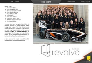
This year our team has gone from 50 to 55
members, including 11 master thesises written
through this project. This has allowed us to
increase the technical complexity of the solutions
and take huge leaps forward in our technical
solutions i.e. 4WD and Torque vectoring. The
weakening of the Norwegian currency difficulted
funding, but our marketing group managed to pull
the team through and finance the project.
A core-team of 17 people was established to
complete testing during the entire summer.
Eirik J. Larsen The team Introduction Sheet ‹#› / 12
2. Eirik J. Larsen Design process Tools and management Sheet ‹#› / 12
Management tools
Meetings
Weekly board meetings
Weekly technical groupleader meetings
Weekly group meetings
Weekly gathering with entire team for progress update
Project plan
Asana
Google drive
Part status documents
Weight budget
Concept approval
Every member is responsible for their own part/system
Technical tools
Solidworks PDM
Design approval of parts and assembly
Machine drawing approval
Altium
PCB design software
Altium Vault
PCB design release approval
Common database w/components
Star CCM+
Fluid analysis w/supercomputer access
KISSSoft
Strength analysis in gears
Hyperworks
FEM analysis
OptiStruct
Topology optimization software for 3D printing
3. Eirik J. Larsen Design process Design approach Sheet ‹#› / 12
Design approach:
When designing Gnist, the following approach was
chosen
1. Choose drivetrain (RWD vs. AWD)
2. Suspension model
3. Packaging
4. Sub-assemblies
5. Monocoque
6. Aerodynamics
Capacity and voltage
Battery cells
Cell configuration
Accumulator design
Battery management
Several systems implemented simultaneously
demands clear communication and continous follow-
up between groups. To complete the car in 8
months, the organization structure was laid out so
that all members have to communicate with all
interfering systems.
63.94 s 4WD
64.58 s RWD
110km/h top speed,
FSAE autocross FSG 2012
Time / Speed, RWD vs. 4WD single lap autocrossProject timeline
Board March 2015 ->
Group leaders May 2015 ->
Overall concepts August 2015
Group members September
2015
->
Concept phase Mid
September
1st of
November
Design phase November Mid January
Production phase January May
Test phase May August 2016
3.4 s 4WD
3.57 s RWD
110km/h top speed,
FSAE acceleration 0-75m
Time / Speed, RWD vs. 4WD 0-75m
4. Choice of drivetrain
The different motor-possibilities we evaluated for
2016 was:
RWD one motor
One single motor in the rear of the car
w/mechanical differential
RWD two separate motors
Two motors w/electronic differential and limited
torque vectoring capabilities
AWD Four motors
Four separate motors w/ full torque vectoring
capabilities
The AWD concept allows for higher total torque
output wich is desirable for the formula student
tracks, and also allows us to implement Torque
vectoring - again increasing performance of the
car.
When choosing a 4WD concept, several drivetrain
alternatives were evaluated:
Inboard motors
Inboard motor with hub-mounted transmission
allows for less unsprung mass on the cost of higher
total weight and high speed rotating shafts.
Inboard motors with lowered CG
This allows us to lower the motors to the floor of
the monocoque, but creates the need of a
sequential transmission inside.
Hub-mounted motors w/planetary gearbox
This increases complexity in a small design
environment and increases the unsprung mass, but
the total weight goes down and removes the need
of 2 transmission systems and the driveshaft giving
less loss.
Eirik J. Larsen Drivetrain choice 4WD vs RWD Sheet ‹#› / 12
5. Torque output of 4x AMK DD5-14-10 vs one Emrax 228 adjusted to 73kW of max output vs
4x AMK DD5-14-10 adjusted for correct efficiency
Eirik J. Larsen Drivetrain choice Conclusion Sheet ‹#› / 12
Motor
Weight
[kg]
Torque
[Nm]
Geared
torque [Nm]
Power [kW]
Torque/
Weight
Size [m^3]
Diameter
[mm]
Moment of
inerta
[kg*cm^2]
Yasa 750 33 790 2013 200 61 0,007 350 Very high
Yasa 400 24 360 2117 165 88 0,006 280 High
Emrax 207
w/different
ial
11,4 140 768 70 67 0,003 207 256
Emrax 228
w/different
ial
14,4 240 1116 100 78 0,004 228 421
4x AMK
DD5-14-10
14,2 84 1303 148 93 0,003 96 10,96
Conclusion
A 4WD design proved to be performing better than
the other alternatives and this lead to a further
research of several alternatives. The chosen concept
is a 4WD car with hub-mounted motors and
compound planetary gearboxes integrated into 3D
printed uprights in grade-5 titanium.
6. Eirik J. Larsen Monocoque Summary Sheet ‹#› / 12
CFRP monocoque
19kg
Integrated accumulator container 46kg
Composite AIP
950g
Composite crash nose
944g
A CFRP monocoque was chosen to achieve high stiffness and safety for the driver. This
also allowed us to integrate the accumulator into the design and make integrated
brackets for the suspension.
7. Eirik J. Larsen Suspension Summary Sheet ‹#› / 12
Key design features:
- 4 individual hub mounted compound planetary
gearboxes.
- Two-piece full CFRP rims
- Pushrod actuated, double un-even a-arm,
suspension system.
- Compact z-bar, ARB design.
- Custom CFRP steering wheel with 3D scanned
grips.
- Topology optimized, 3D printed titanium
upright.
- Development of our own permanent magnet
synchronous motor.
- Focus on high serviceability and DFM/DFA.
8. Ergonomics and driver’s environment 2016
● Focus on close cooperation with previous and
new drivers
● Total weight
○ Seat: 639 g
○ Head restraint: 74 g
○ Dashboard w/electronics: 265 g
Seat
● Optimized carbon fiber and core layup in seat
● Fire retardant epoxy
● Cobber mesh grounding
It was decided on an early stage to re-use and
develop last years solution. This decision was
based on previous and new drivers preferences.
High performance carbon fiber and rohacell core
was used for optimized stiffness and weight.
Head restraint
● Adjustable
● Fire retardant materials
Due to closer distance between head restraint and
rear wing on this years car, the head restraint was
made adjustable to improve airflow to the rear
wing.
Dashboard
● Simplified assembly and use
● Functional and smooth interface
Attachment of the dashboard was made easier and
more functional for the race engineers.
Monocoque, Sindre Sataslåtten Ergonomics Summary Sheet ‹#› / 12
9. Aerodynamics, Anders Hauglid Aerodynamics Aero data summary Sheet ‹#› /12
Rear wing
CL
3.26
CD
1.59
Aref
0.376
L/D
2.05
Front wing
CL
7.34
CD
1.07
A
Sidetray and sidepod
CL 2.28
CD 0.73
Aref 0.312
L/D 3.12
Characteristics Value
Downforce 550 [N]
Drag 244[N]
Downforce / drag 2.25
C_l 3.6
C_d 1.6
Frontal area 1.103 [m2]
Moment about CG +12 Nm
* At 60 kph
10. Sidetray and sidepod assembly: 4878 gr.
Rear wing assembly with fasteners: 4065 gr.
Aerodynamics, Anders Hauglid Aerodynamics System weight overview Sheet ‹#› / 12
Front wing assembly with fasteners: 4168 gr. Cooling systems assembly: 4012 gr.
Total aerodynamic assembly with cooling systems: 17 223 gr.
11. Power systems, Kristian Roaldsnes Power systems Cell choice Sheet ‹#› / 12
Summary
A major advantage of the 4WD concept is the
increased ability to brake on the motors and store
the generated energy in the accumulator. This puts
an intensive load on the battery, which can
potentially lead to battery failure with its associated
risks of fires. One is often forced to sacrifice weight
or total capacity in favour of safety.
With this in mind, the following have been
achieved:
● Battery cells characteristics:
○ LiCoO 6.55 Ah, Melasta Pouch cells
○ Specific energy: 196
Wh/kg
○ Total weight in car: 37.44 kg
○ Max burst charge : 80 A
● Battery stack features:
○ 12 stacks, 2p12s
○ Total 2p144s for 605V max voltage
● Cell tests have been performed to investigate
safety and performance aspects
○ Cell degradation
○ Temperature characteristics
○ Cooling effect of charging currents
○ Charging current limits
○ Disassembly to verify quality
○ Overcharge tests on single cell
○ Overcharge test on segment
12. Bilde/graf/tabellTekstboks
Bilde/graf/tabell
Eirik J. Larsen LV-Electronics Summary Sheet ‹#› / 12
22.2 V GLV battery
Runtime of about 40 minutes w/full power
on all fans
Two separate CAN networks
15 unique in-house designed PCBs
17 units communicating on the network(s)
In-house designed ECU controlling the four
inverters
AMS with a master-slave configuration consisting
of 12 slaves mounted directly on each
module.
Cooling control board with overheat detection
and adjustable duty cycle for optimal power
management.
Telemetry w/ 500m range and up to 2Mbit/s
transfer rates. Able to utilize both the 2.4
GHz and 5 GHz band.
High resolution (16bit), filtered output ADC
modules, processing the output of 16
different sensors.