1. Universities Space Research Association – NASA Internship Final Report
1
Rotorcraft Mechanical Systems
Mark Reyad1
The City College of New York – CUNY, New York, NY
Abstract
The Aeromechanics Branch at NASA Ames Research Center conducts vertical lift research and
conducts many research projects. These projects vary from designing wind tunnel test models, to
rotorcraft acoustic studies, to configuring the capabilities of the next-generation civilian tiltrotor.
Because of these various different projects, the Mechanical Systems Team has a large responsibility
to ensure all equipment and test apparatus are properly prepared and completed for safe and
accurate research. The Tiltrotor Test Rig (TTR) has been in development since 2008 in a joint project
with NASA, the U.S. Army, the U.S. Air Force, and Bell Helicopter. The TTR contains a complex
internal rotor balance system designed to measure force and moment data experienced during rotor
operation when it undergoes testing in the National Full-Scale Aerodynamics Complex (NFAC)
simulating actual flight conditions. When completed, the TTR will evaluate full-scale proprotors in
simulated flight, which will give insight to technological requirements and potential benefits of large
tiltrotors. In September 2014 under a very tight development schedule, an aerodynamic boom
assembly was completed and test mounted onto an ASTAR 350B helicopter. The helicopter-boom
assembly was successfully flown at the end of Fall 2014 in two separate acoustic test campaigns
investigating noise generation reduction in helicopters. In another project, the high bay area in
building N-243 Rotunda will be turned into a test flight and analysis center for small-scale unmanned
aerial vehicles (UAVs) in the near future. To begin the process, the current high bay was modeled
with great detail documenting where the locations of permanent objects were located such as power
outlets, roll up doors, regular doors, windows, stairs, and ramps.
Nomenclature
CAD = Computer Aided Design
FEM = Finite Element Analysis Method
LRTA = Large Rotor Test Apparatus
NFAC = National Full-Scale Aerodynamics Complex
OAT = Outside Air Temperature Sensor
PSAP = Pressure Sensor
RTA = Rotor Test Apparatus
SETRA = Relative Pressure Transducer
TTR = Tiltrotor Test Rig
UAVs = Unmanned Aerial Vehicles
VSTOL = Vertical/Short Takeoff or Landing
1
Undergraduate Intern, Rotorcraft Aeromechanics, Ames Research Center, The City College of New York − CUNY
2. Universities Space Research Association – NASA Internship Final Report
2
Introduction
The Aeromechanics Branch at NASA Ames Research Center conducts various research projects which
encompass many different fields of flight and explore the future of vertical flight. The Branch has been
responsible for research that advances both helicopter and tiltrotor technology. In the past, the Branch has
been has been responsible for creating test rigs for rotorcraft systems - the Rotor Test Apparatus (RTA)
and the Large Rotor Test Apparatus (LRTA). The Branch works closely with the U.S. Army, the U.S. Air
Force, wind tunnel engineers, and several different aircraft companies all with the same goal of advancing
vertical lift research. One of these major collaborations is with Bell Helicopter on the Tiltrotor Test Rig
(TTR). The TTR will provide detailed information about the capabilities and requirements of future
civilian tiltrotors when tested in the NFAC
The Mechanical Systems Team supports all ongoing projects by supplying all hardware that is needed for
research testing. From the very beginning of the conceptual and preliminary designs of a system,
subsystem, or component part all the way to its fabrication and installation onto the rig or experimental
model, the Mechanical Systems Team is present and overseeing all processes to ensure each system is
produced and can operate properly and safely.
Since 2008, the Mechanical Systems Team has been working on the design and production of the TTR.
This work continued in Fall 2014. This included the design and fabrication of critical hardware needed
for calibration of the TTR internal balance. Other projects in the Mechanical Systems Team this fall
include the development and flight test of a helicopter aerodynamic boom and a 3-D model of the N243R
High Bay.
I. The Tiltrotor Test Rig
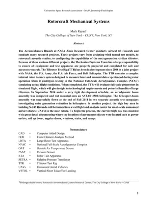
Due to the increased frequency of air traffic in recent years, airport use has become very constrained and
Figure 1: The Tiltrotor Test Rig (TTR) on the maintenance stand before placement on calibration frame.
3. Universities Space Research Association – NASA Internship Final Report
3
difficult to schedule. Because of this trend, a vertical/short takeoff or landing (VSTOL) aircraft would be
very attractive to the public sector. A type of VSTOL that has the qualities of both an airplane and a
helicopter is a tiltrotor (Ref. 3). Tiltrotors are aircraft that generate lift (in hovering flight) and propulsion
(in forward flight) using powered rotors attached at the ends of fixed wings. Currently, the tiltrotor’s
services are limited to the military (the V-22 Osprey); but a project is in development to conduct research
to make tiltrotors commercially feasible for civilian use. This project is called the Tiltrotor Test Rig
(TTR). The TTR includes four electric motors capable of providing up to 6,000 hp and can be tested in
the 40- by 80-Foot Wind Tunnel of the NFAC. The TTR is an experimental test model that contains a
complex internal rotor balance system designed to measure force and moment data experienced during
rotor operation when it undergoes testing in the NFAC. With the information gathered from this project,
future engineers and designers will know the proficiencies and constraints of large-scale tiltrotors to be
used when production of commercial tiltrotors begins (Ref. 4). The Mechanical Systems Team must
ensure all hardware and equipment that is required for testing is fabricated to safe standards to withstand
testing and even possible long-term storage.
A. Calibration Rig Hardware – Critical Lift
The calibration rig that was designed and built to calibrate the TTR internal rotor balance is located in
building N-246 at NASA Ames Research Center. The TTR was moved from its maintenance stand unto
the calibration stand in October of 2014. This critical lift had a number of challenges, including the
overhead bridge crane located in N-246 having a maximum weight limit 30,000 lbs, while the TTR
weighs approximately 60,000 lbs (with motors installed and all fluids full). Because of this, a large
external crane was brought in to assist in moving the TTR onto the Calibration Rig. New configurations
of the TTR were calculated so the tension in the hoist cable connected to the overhead bridge crane would
not exceed its maximum limit. As shown in Figure 3, the overhead crane was attached to the front hoist
ring while the external crane was attached to the two rear hoist rings. The configurations that were
considered include: top moment arm removed; front, right-hand motor removed; rear, left-hand motor
removed; two front motors removed; and two rear motors removed, as shown in Figure 4.
Figure 2: CAD model of the TTR Calibration Rig in N-246
4. Universities Space Research Association – NASA Internship Final Report
4
Figure 4: Critical Lift Options (Ref. 2)
Figure 3: Rigging of the TTR during critical lift (Ref. 2)
5. Universities Space Research Association – NASA Internship Final Report
5
It was decided that if and when the overhead bridge crane was near its maximum limit, lift option number
6 would come into effect. However, during the critical lift, the total weight lifted by the overhead bridge
crane was less than the maximum load of the bridge crane (as measured by an in-line load cell) and none
of the options had to be implemented. The TTR was safely lifted, placed, and locked into place on the
TTR Calibration Rig.
B. Calibration
Contained within the TTR model is an internal balance that is capable of measuring forces generated by
the rotor. It can measure internal forces up to 30,000 lbs of rotor thrust. Before this internal balance is
used for testing, it must be calibrated to ensure accurate measurement readings. The calibration stand
allows application of carefully generated forces using actuators while the TTR itself is mounted in exactly
the same way it will be mounted in the 40- by 80-Foot Wind Tunnel. These actuators (with dedicated load
cells in line) will calibrate the six-component internal balance for thrust, torque, pitch and roll moments,
and side and axial forces. Each actuator, as seen in Figure 6, will pull with a certain measured force from
the load cell it is attached to and that certain force should correspond to the reading that the internal
balance of the TTR displays. Each of the 11 actuators are connected to the TTR using the interface
hardware, as seen in Figure 7 with their label abbreviations. The chart in Figure 8 represents what the
abbreviations represent. Loads can be applied individually or in any combined manner.
Figure 5: TTR during Critical Lift
6. Universities Space Research Association – NASA Internship Final Report
6
Figure 7: CAD Model of Interface Hardware connecting actuators to the metric hardware (Without
Deck) (Ref. 1)
Figure 6: CAD rear view of actuator in anchor
7. Universities Space Research Association – NASA Internship Final Report
7
The actuators are attached to the TTR Calibration Rig with individual anchor hardware. They encompass
each of the 11 actuators, which required five different individual designs. They were all similar and
contained common parts, but each also had their differences to make up for the type of load it will be
supporting. The 11 anchor hardware subsystems were all designed by the Mechanical Systems Design
Team. The initial design of the anchor hardware was modeled after similar hardware from the LRTA
Calibration Rig. Changes were made to allow for differences in the application of the forces as well as for
better access to the anchor hardware itself. Currently, all the hardware has been successfully fabricated
and installed. The calibration process will take four months and will begin in mid-January 2015.
C. Spare Motor and Gearbox Long-Term Storage
The TTR motors and gearboxes were both supplied to NASA by the collaborators of the project. NASA
was also given a spare of each to keep in case a motor or gearbox needs to be exchanged for the duration
of its time the TTR is being used at NASA Ames Research Center. However, special accommodations
must be made to ensure that neither the spare gearbox nor engine will deteriorate due to a long-term
buildup of rust. For this, a special air-tight motor and gearbox storage can was designed to store these
valuable pieces of hardware. Engineering technicians will take a large and previously stored canister and
modify it to the team’s design standard so it can be used as a long-term storage container for the spare
engine and gearbox, as seen in Figure 9. After the canister is modified, the engine and gearbox will be
bolted into the container using a plate which was installed during modification. Then, the canister will be
welded shut, pumped of any air, and filled with nitrogen up to 14.7 psi to prevent rusting.
Abbreviation Actual Name
SFN Side Force (Negative)
SFP Side Force (Positive)
AFP Axial Force (Positive)
AFN Axial Force (Negative)
NFP Normal Force (Positive)
PMP Pitch Moment (Positive)
PMN Pitch Moment (Negative)
RMP Roll Moment (Positive)
RMN Roll Moment (Negative)
TQR Torque (Right)
TQL Torque (Left)
Figure 8: Abbreviations of Assembly Hardware (Figure 7)
8. Universities Space Research Association – NASA Internship Final Report
8
The canister with its modifications has already been designed and analyzed. However, the previous
designers failed to analyze the L-beams and supports in their analysis, which were used as supports for
the engine and gearbox as seen in the cross-section view in Figure 10. Two separate analyses were
conducted for the worst case scenarios (which is the combined weight of the motor and gearbox,
10,000lbs, on one support) on each beam and support using the Finite Element Analysis Method (FEM)
in the Creo Parametric computer-aided design program. The analysis of each support was completed and
each beam had acceptable to high factors of safety, as seen in Figure 11.
Figure 9: CAD model of Spare Motor Gearbox Storage Canister
Figure 10: Cross-Section View of Engine and Gearbox Storage Can
L-Beams installed for support
9. Universities Space Research Association – NASA Internship Final Report
9
The displacement due to stress also came out very minimal when analyzed for the worst case scenario, as
seen in Figure 12.
Figure 12: FEM Displacement test of L-Beam support for the Spare Motor Gearbox Storage Can
Figure 11: FEM Stress test of L-Beam support with 27000psi yield strength for the Spare Motor
Gearbox Storage Can
10. Universities Space Research Association – NASA Internship Final Report
10
A possible second design was created again using the Creo Parametric CAD program for the reason that
the current design that includes the can with all its modifications is a complicated procedure and has a
substantial fabrication effort. Currently being developed is a simpler design which will use less material
and require less labor to fabricate than the current design. The new design in progress is a larger, welded
steel box that will allow for more clearance space within the box so engineering technicians can install the
engine and gearbox much more easily. The old and new designs are show in Figure 13, with the old
design shown in Figure 13a and the new design shown in Figure 13b. A more detailed, top view of the
new design is shown in Figure 14.
Old Design New Design
Figures 13a and 13b: New Box Design Compared to Old Can Design
Figure 14: Detailed Top View of the New Engine Box Design
11. Universities Space Research Association – NASA Internship Final Report
11
The new box design will be reviewed by the engineering technicians in the machine shop here at NASA
Ames Research Center using the technical drawings prepared this semester. If the estimated price of the
new box design is lower than the price estimate of the initial can design, a stress analysis will be
undertaken and fabrication of the alternate motor and gearbox storage box will begin.
II. ASTAR 350B AERODYNAMIC BOOM
To better understand helicopter acoustics, flight tests are to be conducted in which the helicopter is flown
over an array of microphones for various flight conditions. In September 2014, the fabrication of an
aerodynamic boom assembly was completed and was mounted onto the flight test AS350B helicopter, as
seen in Figure 15. Once the boom was successfully mounted, the ASTAR 350B was flown at different
flight conditions, which included 80 knots at level flight, 120 knots at level flight, and 80 knots at a 6
degree descent. Attached to the boom is an instrumental pod that contains three different sensors: a
pressure sensor (also called the PSAP), an outside air temperature sensor (also called the OAT), and a
relative pressure transducer (also called the SETRA). These sensors collect data which enable exact
calculation of aircraft airspeed and aircraft angle of attack. These data, together with the ground acoustic
measurements, will ultimately be used to further investigate noise reduction on helicopters.
After the successful fabrication of the ASTAR 350 boom, it had to undergo multiple tests to ensure that it
would not fail or malfunction when it is operating during flight testing.
Figure 15: CAD Model of ASTAR 350B Boom attached to ASTAR Fuselage
12. Universities Space Research Association – NASA Internship Final Report
12
A. Modal Rap Test
The ASTAR 350B Boom underwent a modal rap test to determine the natural frequencies of the boom.
This had to be reviewed to ensure that the natural frequencies of the boom do not coincide with the rotor
rotation frequency during flight. If the two frequencies do synchronize during flight, resonance will occur,
which will likely cause a violent vibration of the boom which could lead to a catastrophic mishap during
flight. The boom was attached to a table at the same locations and in the same manner as it would be
attached to the helicopter. After test installation, three electronic accelerometers were attached onto the
boom and plugged into a data collector, as seen in Figure 16. A soft-tipped hammer was used to excite the
boom in bending. An engineer proceeds to lightly hit the boom. After the hammer hits the boom, the
accelerometers pick up the vibration that is occurring within the boom and sends the information to the
data collector. Next, the data collector sends the information to a computer which graphs all of the
vibrating frequencies that are occurring in the boom structure, as seen in Figure 17. The computer then
detects and computes the natural frequencies of the boom. The boom was initially designed to have a
lower natural frequency than the frequency of the rotors and the rap test was a confirmation to ensure that
it met the design standards.
Figure 16: Attachment of Electronic Accelerometers onto ASTAR 350B Boom
13. Universities Space Research Association – NASA Internship Final Report
13
B. Pressure Leak Test
A pressurized hose was connected to the end of the ASTAR 350B boom to test whether or not there was a
leak somewhere along the tubing. The tubing leads from the front nose of the boom, which is open to
measure the pressure outside the helicopter, to the relative pressure transducer (SETRA) inside the
instrumental pod. The pressure readings that were gathered from the SETRA were supposed to match the
input air pressure coming in through the pressurized hose. The boom had failed the test once and the
instrumentation pod covers were removed to access the tubing and the SETRA and determine where or
what was causing the leak. After all the connections were tightly sealed, the boom was retested and
ultimately passed the pressure leak test.
C. Boom Installation and First Test Flight
After the rap and pressure testing, the ASTAR 350B boom was delivered to the Hollister Municipal
Airport in Hollister, CA to be installed onto the helicopter. The boom mounts were first installed onto the
helicopter. After the boom was fully assembled, it was installed onto the helicopter as well. Another rap
test was done to make sure that the actual installation results didn’t vary from the test setup at NASA
Ames, even though the previous setup held the boom in a very similar way that it is attached to the
helicopter. The natural frequencies of the boom were found to be well away from the rotor rotation
harmonics, so no modifications to the installation were required. After the cables were finished being
routed and secured, the instrumentation panel was installed and checked. The helicopter-boom installation
is seen in Figure 18.
Figure 17: Information Sent to Computer from Accelerometers
14. Universities Space Research Association – NASA Internship Final Report
14
After a thorough inspection, the boom was successfully installed and was deemed flightworthy. A photo
of the ASTAR 350B during its first test flight is seen in Figure 19.
Figure 18: The ASTAR 350B Helicopter-Boom Assembly
Figure 19: The ASTAR 350B Helicopter-Boom Assembly during First Test Flight
15. Universities Space Research Association – NASA Internship Final Report
15
III. N243 Rotunda High Bay
Engineers are planning on turning the High Bay in building N-243 Rotunda into a test flight and analysis
center for small-scale unmanned aerial vehicles (UAVs) in the near future. To begin the planning process,
the current high bay will have to be modeled in a CAD software with detail explaining where the
locations of permanent objects are located such as power outlets, roll up doors, regular doors, windows,
stairs, and ramps. The High Bay was measured using a laser measuring device that has an accuracy of
1/16th
in and distances up to 165ft. Small features were measured with a standard tape measure. A
drawing of the N-243 Rotunda ground floor, as seen in Figure 20, was also used to confirm the locations
of larger geometries, such as the garage door. The total modeling time was around 7 hours and measuring
time was around 3 hours with a grand total time of approximately 10 hours.
The high bay was modeled in the Rhinoceros 5 CAD program. A panorama view of the high bay is seen
in Figure 21. An overall view of the CAD model is seen in Figure 22. Supplementary views are seen in
Figures 23 and 24.
Figure 20: Drawing of N-243 Rotunda Ground Floor
16. Universities Space Research Association – NASA Internship Final Report
16
Figure 21: Panorama View of N-243 Rotunda High Bay
Figure 22: Overall CAD model of N-243 Rotunda High Bay
17. Universities Space Research Association – NASA Internship Final Report
17
Figure 23: Eagle-Eye View of High Bay
Figure 24: View of High Bay Details in CAD Model
18. Universities Space Research Association – NASA Internship Final Report
18
IV. Conclusions
The Mechanical Systems Team plays an essential role within the Aeromechanics Branch at NASA Ames
Research Center. Not only does the team develop working designs for testing next-generation rotorcraft
prototypes, but they also provide flight hardware for various projects and wind tunnel tests. Throughout
the last four months, I have been involved with three different projects. All three, the Tiltrotor Test Rig
(TTR), the ASTAR 350B Boom, and the modeling of the N-243 Rotunda High Bay, provided insight into
the full scope of the different operations that go on in the Aeromechanics Branch specifically, and in
mechanical engineering in general. Finally, working on these three projects demonstrated all the thought,
design, review, and analysis that goes into every system, subsystem, or mechanical component prior to
production and use.
Acknowledgments
To the Mechanical Systems Design team (Gina Willink and Jim Kennon) and my amazing mentor (Gina
Willink) - Thank you for the opportunities you have given me to prove myself. Thank you also for pulling
out the best of me as well as for being great role models and acquaintances.
To my supervisor William Warmbrodt - Thank you for granting me the opportunity to experience the
work that occurs at NASA Ames and for convincing me to travel across the country to the Bay Area. It
was a life changing experience that has greatly motivated me and one that I will never forget.
To all my fellow interns - thank you for making this an amazing and enjoyable experience in Northern
California, both at work and after hours.
References
1. Acree, W., Lillie, D., Meyn, L., Sheikman, A. (2014). TTR Balance Calibration: Hardware
Configurations. [Slides 5 – 7]
2. Hartley, C. (2014). Tilt-Rotor Test Rig (TTR) Weight & CG Estimate. [Slides 10 – 12]
3. Luidens, R. W., & United States. (1984). Supersonic STOVL aircraft from a propulsion point of view.
Washington, D.C: National Aeronautics and Space Administration.
4. Tiltrotor Test Rig. (2014). NASA Ames Research Center: Rotorcraft Aeromechanics. Retrieved from
http://rotorcraft.arc.nasa.gov/Research/facilities/ttr.html