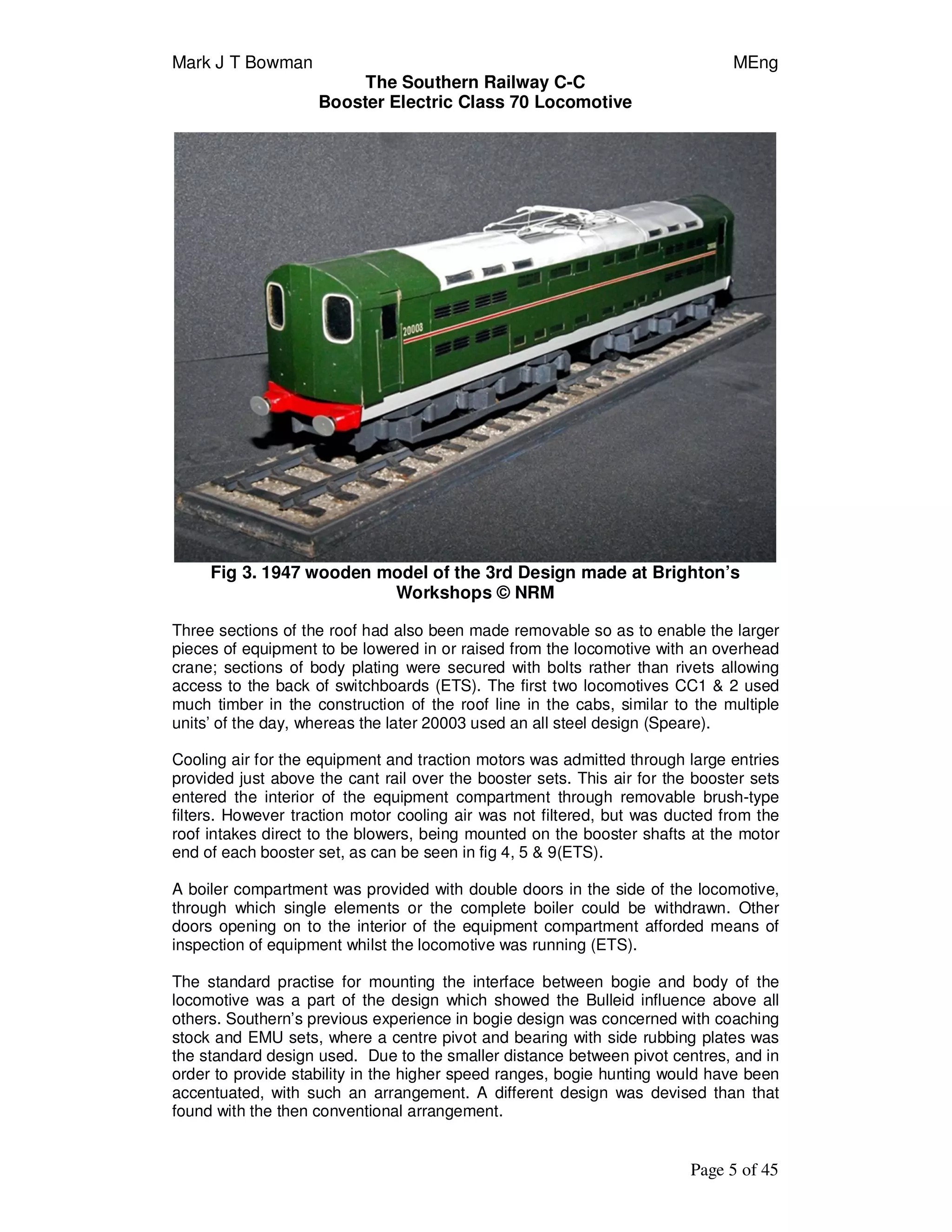
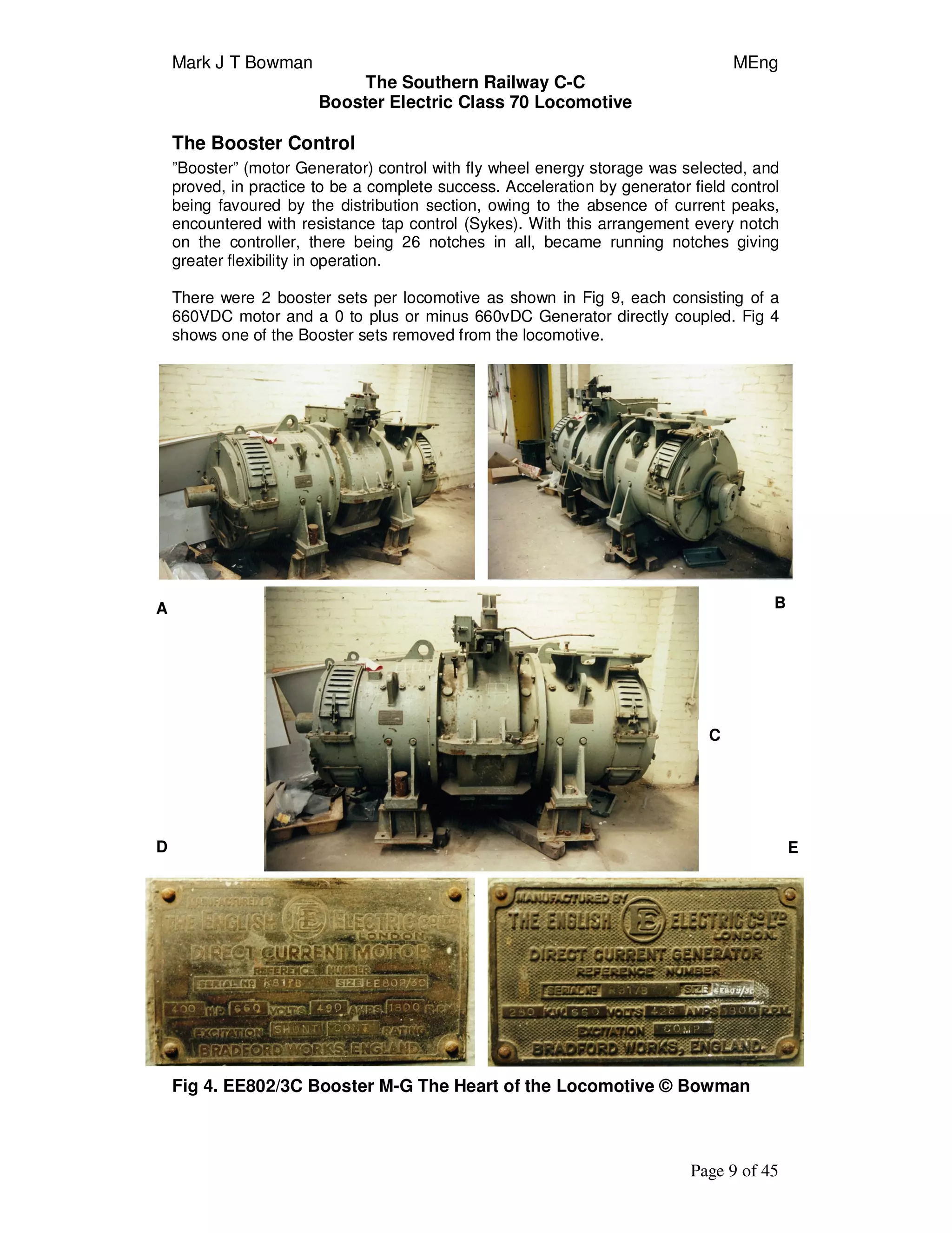
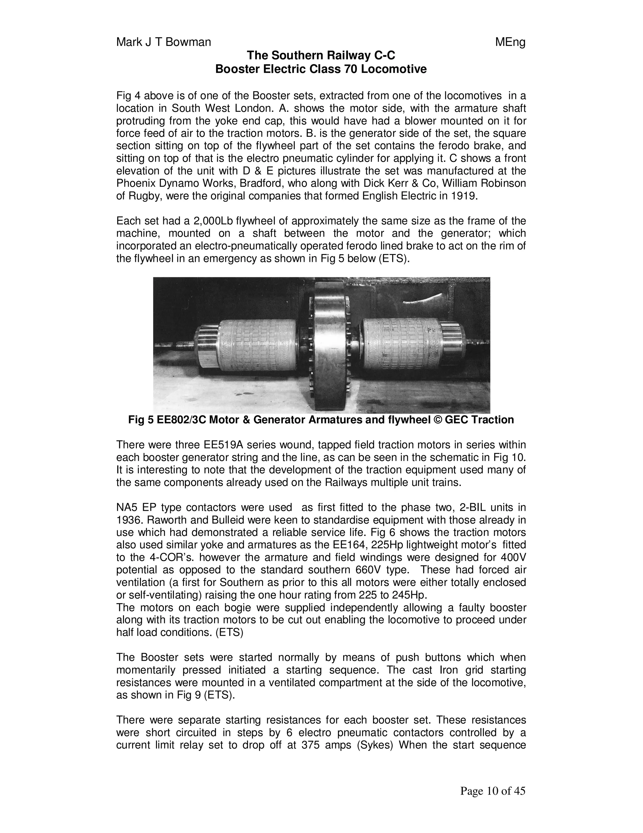
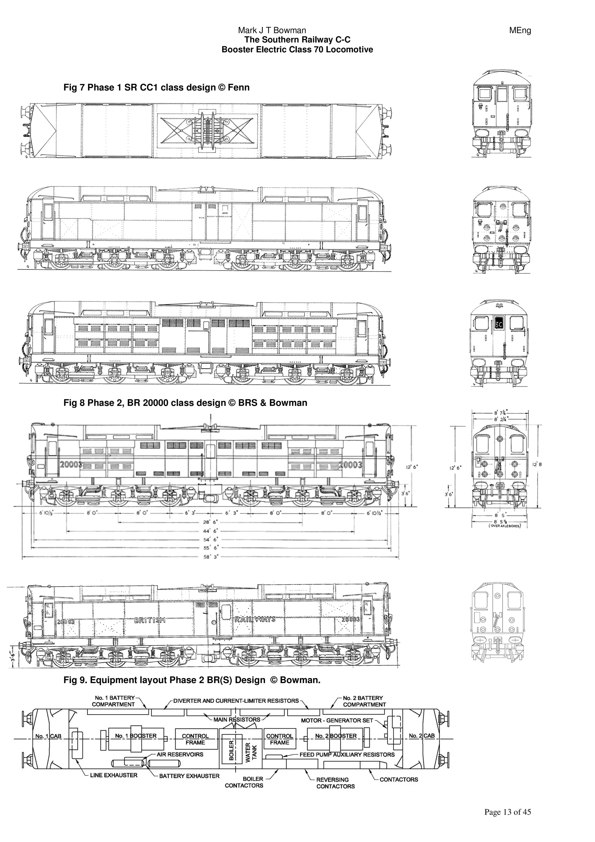
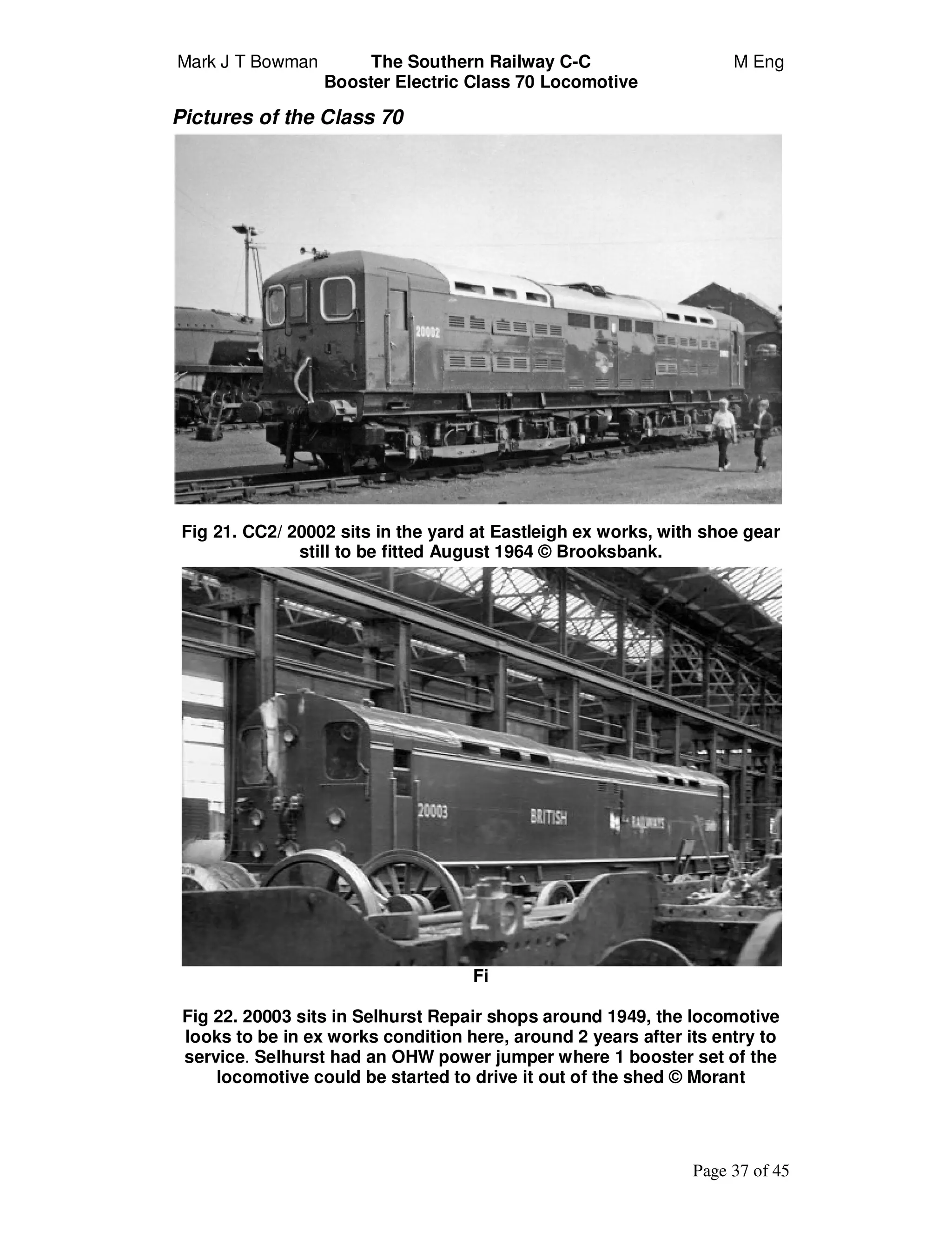
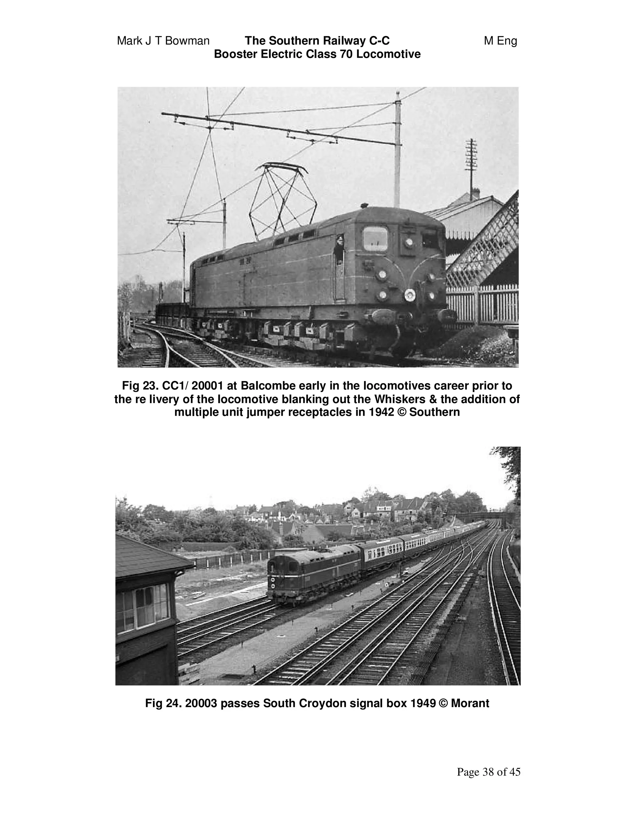
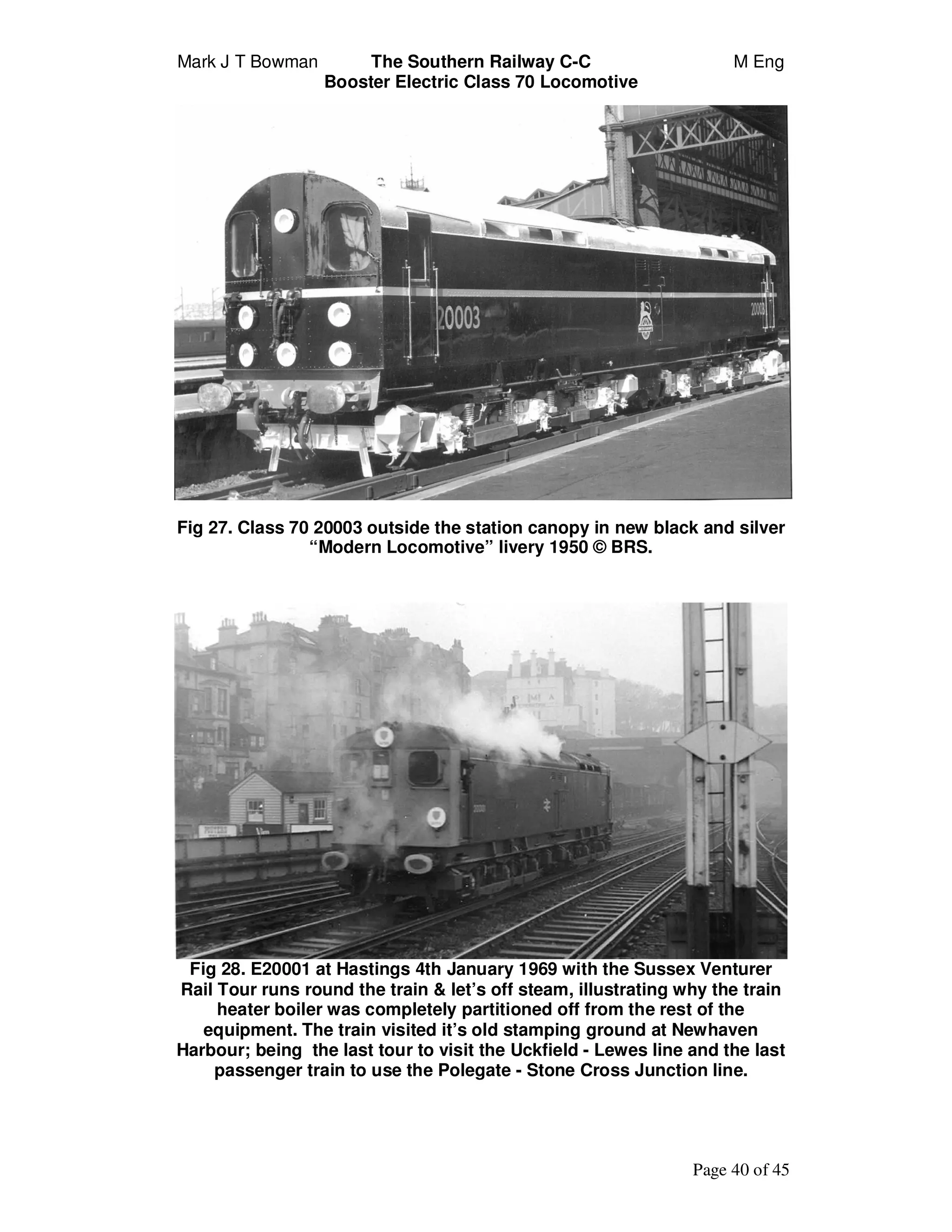
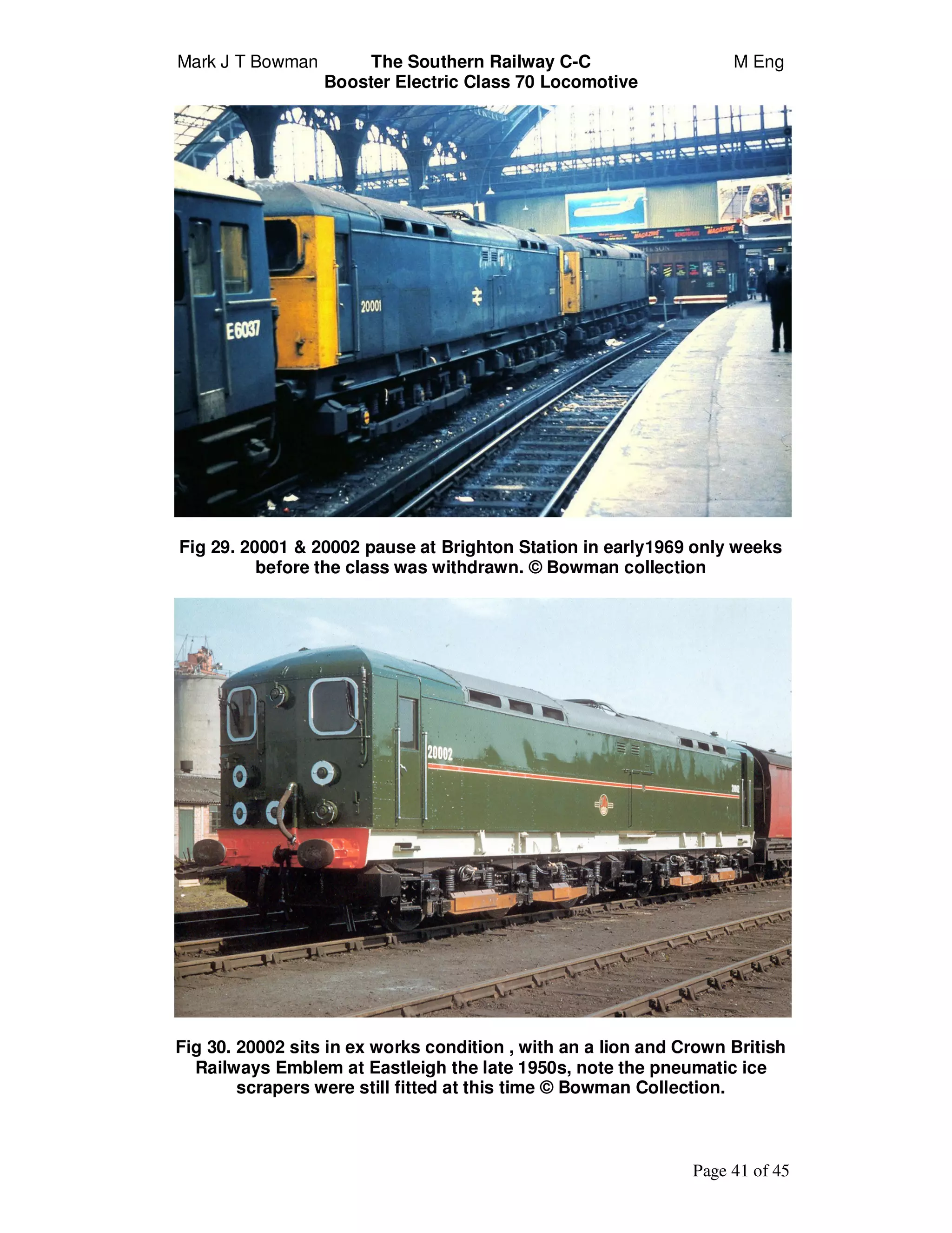
4. Mark J T Bowman MEng
The Southern Railway C-C
Booster Electric Class 70 Locomotive
Page 4 of 45
was also utilised BR’s first mass production diesel electric locomotives the class 40,
44, 45 and 46.
Alfred Raworth developed the control system in association with the main electrical
equipment supplier English Electric who had entered into a 10 year contract with the
Southern Railway in 1936. O.V.S Bulleid designed the mechanical aspects of the
locomotive the two disciplines have been separately discussed in this paper to
demonstrate the novel advances made by the two men in their separate designs.
The problems encountered in designing a locomotive of such originality led to
differences in design between the three locomotives built during a period of years.
The third locomotive introduced in 1948 & shown in Fig 3 & 8 carries the
accumulated experience of the three machines and is discussed here. The design
specification for the first locomotive CC1 called for the hauling of 1000 ton freight
trains, and for 425- ton passenger trains at speeds up to 75 mph (the civil engineers
limit) with a balancing speed on level track of 60mph, being the same as express
multiple unit stock (Tufnell).
Mechanical Design
General Design was carried by Waterloo stations offices, with bogie design being
undertaken at Ashford works, the three axle Co-Co bogies having six traction motors
of 245Hp.
The first two locomotives CC1 & CC2 were built in Ashford to drawing SR 37, being
56ft 9in long, weighing in at 99 tons, with a tractive effort of 40000lb, and were taken
to Brighton for technical fitting out (Speare). The locomotives body was made up of a
conventional style, with tractive and buffing forces being transposed through four I
section longitudinal girder underframe running the full length between the buffers with
outer members making up the sole bars. (Tufnell). Forces were transmitted through
Oleo buffers, and traction transferred to the train via the standard drag box and hook
with a screw coupling arrangement.
The Co-Co wheel arrangement carried a box type body (of Hastings Line Gauge)
with a driving cab at each end and an equipment compartment in the middle. The
centre section of this compartment contained the heating boiler and water tank used
for train heating supply; electrically being completely partitioned off, so that any
escape of steam or water couldn’t enter the equipment compartment (ETS).
The locomotives styling resembled the then current design of multiple units with cab
ends resembling the “Sheba Sub’s” which Bulleid had also influenced. The third
locomotive 20003 unlike its earlier sisters was built and fitted out completely in
Brighton
Fig 3 shows the wooden model made by Brighton Workshops in 1947 to Ashford
drawing A9043. 20003 being different in its body style built, having styling resembling
the then new post war all steel 4-SUB units, some saying to resemble the Leader
project, also being built at Brighton at that time (Tufnell, Speare).
Each axle carried an axle hung nose suspended traction motor as illustrated in Fig 6
geared to the axle by straight spur gearing, coupled to axles carried on 3’6” BFB
wheel-sets (Speare).
6. Mark J T Bowman MEng
The Southern Railway C-C
Booster Electric Class 70 Locomotive
Page 6 of 45
Also a conventional centre pivot arrangement the bogie would be able to tilt, with a
resulting in a tendency for wheel slip to occur on the leading axle due to unloading
caused by the drawbar reaction of the locomotive on heavy trains (Sykes).
Bulleid originally envisaged that the locomotive would have tractive and buffing
forces contained within an articulated bogie frame, similar to the NSWGR 46 Class,
FS E 626 and his later design for the Leader Steam locomotive. A frictional damping
traction link was specified joining the two bogies together through a partition in the
train heat boiler feed water tank. However this design was changed to the
conventional sole bar mounted drag box and buffer arrangement (Tufnell).
The possibility of hunting had been suspected during the design of the mechanical
parts and despite the lack of bogie mounted draw hooks the frictional damping
coupling was retained. This was later found to be completely unnecessary; it was
removed from the first locomotive and was not installed in the other two. Even with
the absence of the more usual swing bolsters the locomotives were found to ride
steadily and well at all speeds up to 90 mph (ETS).
The centre motors of the Co-Co configuration also excluded the traditional centre
pivot arrangement, instead of adopting an orthodox double bolster arrangement, with
central saddles spanning the middle motor, a segmented bearing design was chosen
under the directorship of Bulleid by Paul Bolland, in charge of bogie design at
Ashford.
This design specified bearings of a segmented form, arranged at each end of the
longitudinal diameter of a 9-ft circle having its midpoint at the centre point of bogie
rotation; pairs of male segments were attached to the underframe over each bogie,
spaced on 26ft 6in centres, as seen in fig 8.
Each segment rested in a trough, rigidly attached to the bogie stretchers located
between the axles of each bogie. The outer vertical side of each segment was
arranged to bear against a working surface located on the adjacent inner side of its
trough, and thus the tractive forces were transmitted from bogie to underframe
(Sykes).
Smaller male segments, located on the underframe at each side on the transverse
centre line of the bogie, also worked in corresponding troughs fixed to the bogies to
control side thrusts. The bogie was thus free to pivot around a virtual centre, but
apart from the working clearances it is not free to move in relation to the body in any
other way (Sykes).
The otherwise exposed portions of all segmental troughs were fitted with close fitting
spectacle plates in order to exclude dirt, enabling the bearing surfaces to be kept
continuously lubricated. In addition to their normal function, these bearings met two
very important requirements. Firstly the provision of a centre bearing, which was
almost 9ft in diameter and secondly it made it impossible for the bogie to tilt in
relation to the underframe even at very high tractive efforts (Sykes).
Under such conditions, both the bogie and the underframe tilt slightly as an integral
unit, but the degree of weight transference was such that very little trouble was
experienced with wheel spin on the leading axles of each bogie, even when drawbar
7. Mark J T Bowman MEng
The Southern Railway C-C
Booster Electric Class 70 Locomotive
Page 7 of 45
reaction was at its maximum. Secondly the large area of each segment had
considerable damping effect on hunting movements (Sykes).
This combined with a moderate amount of spring side control and the long bogie
wheel base almost completely eliminated hunting, even at the highest speeds.
Electrical Design
The locomotive, had an evolution of electrical design, throughout the 7 years
between builds, Alfred Raworth designing the original method of control with C.M
Cock being the Chief Electrical Engineer of the SR when the second locomotive was
built in 1945, and lastly S.B Warder, later the champion of BR’s 25Kv 50 Hz
electrification having input as BR Southern Regions Chief Electrical Engineer in
1948, for the construction of the final locomotive 20003 (ETS, Warder).
The Locomotives were designed to run from 660- 750V DC from a conductor rail
(third rail), in normal operation, and from an overhead wire in shunt yards, this
arrangement was employed to protect shunts men from being electrocuted by a third
rail. This was a necessary safety precaution in the days when loose coupled wagons
were coupled by men with poles running alongside the train.
Tests under the LVDC catenary were carried out on the first locomotive CC1 drawing
power through a pantograph in sidings on the Brighton line near Balcombe tunnel
and proved successful. (Duffy).
Control System Design considerations
As well as the supply problems in sidings and marshalling yards; the electrical design
and its operation needed to take account of the inconsistent supply of power over the
Southern’s third rail network.
The traction system needed to be able to supply constant tractive effort with
intermittent supply of power due to the frequent gaps common on all third rail
networks especially at the entrances to platforms at termini stations where point work
was prevalent, and continual supply was needed most.
Other railways had experimented with special block trains in order to extend the shoe
base of the motive power pick up. (ETS) With the wide variety of traffic Southern
envisaged running with these locomotives, and the dispatch of freight trains onto
other railways within the British Railway network; it was deemed this practice would
be too restrictive. Cost benefit analysis of erecting catenary or overhead 3rd
rail at
complicated junctions had also been discussed, but the costs were viewed as being
excessive as well as disruptive to operation of traffic. (Sykes)
Many freight trains were loose coupled at that time, and the loss of tractive effort and
its re application would cause unacceptable surges throughout the train, this was
evident in early stages of trial running in 1941, with the tripping of the motor over load
relays when in the course of adjustment led to a rebound of the locomotive on a
loose coupled freight train felt most unpleasantly in the brake van toward the rear of
the train (Sykes).
The use of a floating battery had been considered, but the current demands, in the
region of 3,000 Amps and high tractive efforts would have called for a large bulky
battery (Sykes). Raworth looked to the work carried out by one of electric tractions
8. Mark J T Bowman MEng
The Southern Railway C-C
Booster Electric Class 70 Locomotive
Page 8 of 45
pioneers, JJ Heilmann, a French electric traction engineer in order to design a
system which could cope with the complex problem of non-continuous traction
supply.
The Booster system history
In 1918 Heilmann looked to the work carried out by H. Ward Leonard, who worked
with Edison in the mid to late 1880’s to propagate the DC Edison power station
system, he proposed a system in the 1890’s of DC control; using a high-power
amplifier in the multi-kilowatt range, built from rotating electrical machinery. Ward
Leonard’s drive unit consisted of a motor and generator with shafts coupled together.
The motor turned at a constant speed and could be AC or DC powered. The
generator was DC, with separate field and armature windings. The input to the
amplifier was applied to the field windings, and the output coming from the armature.
The amplifier output being connected to a second motor, which moved the load, such
as an elevator. With this arrangement, small changes in current applied to the
control, the generator field, resulted in large changes in the output, allowing smooth
vernier speed control of heavy currents.
Heilmann ran many tests in the 1890’s to prove the suitability of differing traction
systems being proposed at the time for larger scale electrification. He decided early
on the DC traction had advantages over the main technical challenger at the time,
synchronous 3-Phase motors, due to the flexibility in speed control being separated
from the generating plant. In 1893 Heilmann constructed a 120 ton steam electric 8
axle Do-Do locomotive the Fusée Electrique, which was an Edison power station on
rails. However it is his later experiments with DC single phase and multiphase
traction which is of interest here (Duffy).
Heilmann used the Ward Leonard control system on a test locomotive in 1898, in
order to alleviate heavy shock loads on the generator, experienced with the basic
DC rheostaic control of tram equipment’s at the time (Duffy).
Heilmann constructed a DC electric test locomotive utilising Ward Leonard control in
1898, using the bogies from the earlier Fusée Electrique; with testing carried out on
the Western Railway of France between Saint- Germain- Ouest and Saint- Germain-
Grande- Ceinture. Supply was by third rail and overhead wire. The two 4 axle bogies,
had four separately excited motors arranged in parallel on each (Duffy).
The control gear consisted of rotary DC-DC converters with a constant speed motor
fed from the supply, and a DC generator with the field being exited from a DC
generator on the same shaft. The output voltage of the main generator four pole
dynamos being able to supply 1,200 amps at start, was controlled from a
potentiometer in the field circuit and was applied directly to the armature of the 8
traction motors. The field of the traction motors were fed from the constant voltage of
output of the exciter; the speed of the traction motors were therefore controlled over
a wide range 0-400V DC by the potentiometer (Duffy).
It was with this pioneering work in mind which led Raworth, in conjunction with
English Electric to design the control system for the Southern CC class locomotives.
12. Mark J T Bowman MEng
The Southern Railway C-C
Booster Electric Class 70 Locomotive
Page 12 of 45
motors were wedge locked, not banded as in the 519-A motored examples of the
class (Tufnell).
Drivers cab
Despite the mixed traffic nature of the locomotive, in their early lives they were
primarily used on freight trains; with the first regular main line passenger hauled
service not happening until after the war.
This freight use led to a revamp of the cab design in the latter 2 locomotives CC2 &
20003 with duplication of the master and brake controllers, allowing the driver to
control the train from both sides of the cab. This enabled the driver to look back along
the train for signals from the guard when starting freight trains. (Linecar)
Auxiliary lighting compressor exhauster boiler and other control switches are placed
in two auxiliary cupboards mounted one in each driver’s cabs, the cupboards forming
part of the partitions between the driver’s cabs and the main equipment compartment
(ETS).
All booster control buttons and lights were mounted on a panel attached to the centre
of the front wall of the cab, with individual “start”, “stop and brake” buttons for the
control of each of the four boosters, which can be started and stopped independently
for multiple locomotives controlled from one cab (ETS). CC2 & 20003 locomotives
had the AAR Standard 27 way jumper receptacles fitted to the nose end in order to
allow multiple running as described later, with CC1 also gaining this addition in the
late 1940’s (Linecar).
The drivers desk comprised of two ammeters one per booster set in front of the
driver. To assist him the normal accelerating currents were shown by red marks on
the scales (ETS). The early notches were graded so as to allow very slow start when
working loose coupled freight trains and the large number of notches made it
possible to choose one for any running condition (Sykes). Other gauges comprised of
a speedometer, brake cylinder pressure gauge, vacuum gauge and a train pipe and
main reservoir duplex gauge. The desk also had a whistle and wind screen wiper
control valve and overload reset button.
The Master Controller was mounted inside the driver’s desk and consisted of a drum
carrying a number of cams, cut from insulating material each of which operated
through its follower a silver butt contact switch (ETS). From the sparse information
concerning locomotive number 1 the controller was on one side only, and a lever in
the traditional style was moved round 26 individual notches. The mode of operation
was similar to the direct control tramway equipment master controllers, whereas
locomotive number 2 having a horizontal controller (Tufnell).
Locomotive number 3 was different again, comprising of a Horizontal drum with
insulated cams attached, driven from the controller hand wheel (in the French style)
by bevel gearing. In addition to the control wheel on the driver’s side a reversing
handle with “Reverse” “Off” “Forward Full Field” & “Forward Weak Field”, and on the
other side the control key switch, which has “On” & “Off” the handle being removable
in the off position only (ETS).
Mechanical interlocking in the controller was such that no conflicting movements
could be made: when the control key switch is thrown to on the reverser handle may
then be moved to forward FF or reverse it being then impossible to reverse the
control key switch to off (ETS).
14. Mark J T Bowman MEng
The Southern Railway C-C
Booster Electric Class 70 Locomotive
Page 14 of 45
Key to Schematic Abbreviations
A Ammeter C.L.S.1 & C.L.S.2 Current Limiting Shorting contactor L.B.1 & L.B.2 Line Breaker Contactor S.F Series Field
AUX Auxiliary Generator C.O.S.W Change Over Switch L.F Line Field SUB RES Substitute Resistor
B.F. Battery Field DIS. RES Discharge Resistor L.F.1 & L.F.2 Line Field regulating Contactor T.M Traction Motor
B.F.1- B.F.6 Battery Field Contactors D.R Differential Relay L.F.R.1 & L.F.R.2 Line Field Reversing Contactor U.V.R Under Voltage Relay
B.F.R.1 & B.F.R.2 Battery Field Reversing Contactors E.F.R (E.C) Earth Fault Relay (Earth Coil) L.R Limiter Relay V.R Voltage Relay
B.G.1 & B.G.2 Booster Generators E.F.R (L.C) Earth Fault Relay (Line Coil) M.1 & M.2 Motor Contactor W.F Weak Field
B.M.1 & B.M.2 Booster Motors F.C.O.1 & F.C.O.2 Field Change Over Switches R.1 – R.5 Starting Contactor
B.M.B.F.1 & B.M.B.F.2 Booster Motor Battery Fields F.D.C.1 & F.D.C.2 Field Diverter Contactor R.C.C Reveres Current Contactor
B.M.F.1 & B.M.F.2 Booster Motor Battery Fields Contactors F.F Full Field R.E.S Resistor
C.F Compensating Field I.L Isolating Link R.R.1-R.R.5 Starting Contactor
C.L.R Current Limit Relay I.P Interpole R.S Resistance Shorting Contactor
Fig 10. Traction Schematic (Sykes)
15. Mark J T Bowman The Southern Railway C-C M Eng
Booster Electric Class 70 Locomotive
Page 15 of 45
The main hand wheel could then be moved away from its off position to notch 1 the
first power notch. With regards to the traction circuit the effects of the control system
from notch 1 through to 15 the traction circuit was in “Buck (ETS). The line field
contactor LFR1 was closed with LFR2 open, causing a reverse or buck voltage to be
produced by the booster generator so that the current flows through the generator in a
direction opposing the EMF generated by it, thus throttling back the flow of current
from the line. The Booster generator therefore acted as a motor delivering power to the
shaft, with the power absorbed by the booster motor which acted as a shunt generator.
In this condition the voltage across the three traction motors (X) in series = Line Volts -
Booster Generator volts, with X being equal to 15 Volts in notch 1 “full Buck” as
illustrated in fig 11. (ETS)
Fig 11. Booster Generator “Bucking Notch 1”.
Where the current drawn from the line being equal to the current consumed by the
traction motors minus the current generated by the booster motor or (I line = ITM –
IBM) (ETS).
Notch 2 through to 15 gradually decreases the current passing through the generator
field, there being 2 fields per booster, one which is fed from line voltage, shown as
Current Distribution Voltage Distribution
IL ITM
+ 660V
IBM
Volts Above Earth
0 200 400 600V
X
X
X
600- (3x)
B M B G
Key
Booster Motor Current
Traction Motor & Line Current
16. Mark J T Bowman The Southern Railway C-C M Eng
Booster Electric Class 70 Locomotive
Page 16 of 45
Booster Generator Line Field (B.G.L.F) on the traction schematic and secondly the
Battery Field (B.F).
Regulating resistors are in series with both fields, shorted by tapping contactors to
control the field strengths. BGLF has four strengths with LF1 & LF2 (the series
resistance tap contactors) both being energised up to notch 3 and LF2 dropping out at
notch 9 inserting all the resistance into the line field, with the field being open circuited
at notch 12 extinguishing all line excitation to the booster generator at that point in the
Buck mode of operation.
It is the action of the variable four stage excitation of the line field that compensates for
the fluctuations in line voltage. The Battery field had 13 differing levels of excitation
with each increment of the battery field regulating resistor having differing values of
resistance, making a total of 16 differing combinations possible from 6 resistance taps,
when taken in conjunction with the four differing stages of compensating line
excitation.
Once notch 16 was reached the battery field contactors BFR1 are also open circuit like
the line field, thus decreasing the voltage drop across the booster generator and
increasing the voltage seen across the three traction motors increasing the value of X
Fig 12. Booster Generator Unexcited (notch 16)
On the middle notch of the controller (16) the voltage across the generator terminals
was zero and the full line voltage was seen across the traction motors, these being of
400VDC rating making 600V/ 3 giving 200VDC across each motor or half power, as
illustrated in fig 12.
Current Distribution Voltage Distribution
IL ITM
+ 660V
IBM
Volts Above Earth
0 200 400 600V
200v
200v
200v
(600- 3X)
B M GB
17. Mark J T Bowman The Southern Railway C-C M Eng
Booster Electric Class 70 Locomotive
Page 17 of 45
Reference to fig 10 the traction schematic shows the positions of LFR1 & LFR2 and
BF1 & BF2 these being the reverser contactors for the generator fields for the booster
generators. Reference to the power chart shows both of these contactors open at point
16. With LB1 & LB2, RR1 & RR2 RS1& RS2 closed on the Booster Motor Armature
feed side BMF1 & BMF2 closed on the Booster Motor Field side and M1 & M2, closed,
on the traction motor circuit.
Further rotation of the controller reached notch 17 seeing BFR2 close thus re-
establishing the battery generator field, but this time energised in the opposite direction
than experienced in notches 0-15. The booster motor acts as a motor and the booster
generator acts as a generator thus allowing the booster generator EMF assist the line
voltage, in this configuration the line voltage across the three traction motors in series
= line volts + booster generator volts (ETS).
The battery and line field contactors are bought in at various stages from notch 17 to
full application at notch 23; Notch 19 sees the introduction of the first stage of line field
excitation with the closing of (LFR2) then at notch 21 (LF2), then (LF1) closing in notch
22 energising the line excitation field at full power.
Full boost being achieved at notch 23 with the closing of all battery field contactors,
this is approximately double line voltage so that the voltage across each motor is
1,200/ 3 = 400Volts; this being the rated voltage of the traction motors.
As can be seen in the voltage and current distribution diagram in fig 13, at no time
does the boosted supply exceed the line potential to earth, with the booster generator
assisting the supply by accelerating the voltage across it and the two traction motors
either side of it with a negative potential, shown as -600V representing notch 23.
Notches 24, 25 & 26 control field weakening of the traction motors (another first for an
SR design) by two stages of field diversion finishing with a field tap stage. This system
of giving weak field to increase the balancing speed of the traction motors was trialled
on the “booster Locos” and replicated 10 years later on the 51 Stock suburban EPB
sets
The EPB’s originally had two stages of field divert, and field tap like the boosters, but
were re-configured in the mid 1950’s to single stage field tap, due to high incidents of
traction motor flash over.
These final three weak field notches could not be taken until the reverser handle was
moved into to “Forward Weak Field” against a spring. On notching the controller back
below notch 24, the reverser handle flew back to “Forward Full Field” position, the
mechanical interlocking then prevented the selection of the weak field notches before
the handle is moved back to “Forward Weak Field” (ETS).
18. Mark J T Bowman The Southern Railway C-C M Eng
Booster Electric Class 70 Locomotive
Page 18 of 45
Fig 13. Booster Generator “Boosting” (Notches 17 to 26)
Operation over a gap
If at any time whilst the locomotive was under power, and the traction supply is lost,
with the collector shoes entering a gap, a no current relay de energises opening its
contacts, which in turn opens the line breakers, and inserts all resistance in series with
the booster motors. Each booster set is kept running by the 2,000-Lb fly wheel
mounted on the common shaft between motor and generator.
All other circuit conditions remain as before, except that the booster motor acts as a
shunt generator across the traction motor group. The load is thus seamlessly taken
over by the booster sets, and tractive effort decreases slowly as the set slows down.
When the shoes are again energised, the line breakers close through voltage relays,
strung across the motor group line switches, and the resistances are cut out step by
step under the control of separate Current Limit Relays CLR with a higher setting of
800 amp, since both the booster motors and traction motors are now in circuit, as two
parallel paths.
Service experience showed that the 2,000Lb flywheel capacity was sufficient to meet
all normal requirements in the longest conductor rail gaps and operation was entirely
successful.
Safety Interlocks
Whenever the main hand wheel was away from the off position neither the reverser
handle nor the control key switch could be turned to the off position. When the reverser
handle is not in an off position a dead man’s pedal, their being two in each cab, one at
each side under the desk, had to be kept depressed by the drivers foot. Release of the
pedal leads to the opening of M1 & M2 contactors shutting off the feed to the traction
motors and then after a time delay, a brake application in two stages, described later,
Current Distribution Voltage Distribution
IL
ITM+ 660V
IBM
Volts Above Earth
-200v 0 200 400 600V
400v
400v
400v
-600v
B M B G
19. Mark J T Bowman The Southern Railway C-C M Eng
Booster Electric Class 70 Locomotive
Page 19 of 45
both on the locomotive then the train if vacuum braked (ETS). The rate of acceleration
was under the control of the driver, subject to the overriding control of the overload
relays; so that motor accelerating current was kept at approximately 750 amp.
As described, a portion of the field winding to each booster set generator was fed from
a battery. The battery field windings for each booster set were in series with one
another along with a bank of control resistances. There were also excitation fields fed
from the line power supply, with field reversal and discharging effected by specially
designed electro pneumatic contactors (Sykes).
Power supply to the traction motors is governed electro- pneumatic reversers and
contactors operated from the master controller, the field tap is selected from a an
electro pneumatic change over switch (ETS).
So far as possible the motors on the two bogies and their associated electrical control
equipment were kept electrically and physically separate, so that no fault will disable
more than half the locomotives tractive effort.(Sykes) Reference to fig 10 traction
schematic shows removable isolating links situated to between the No-Current Relay
and each booster sets main Overload Relays, giving the opportunity to completely
isolate the traction supply from individual booster sets. The control systems which
share circuits, such as the generator battery and line fields had knife switches installed
with substitute resistances to replace any one of the fields on either booster set
(Sykes).
Fig 9 shows the disposition of the main control equipment, which was mounted on two
main equipment frames either side of the boiler compartment. Each frame carried the
line breakers contactors the booster starting contactors, reversers, field tap switch
relays etc. belonging to one booster set and its three associated traction motors. The
No. 1 frame housed in addition the shoe isolating switch (for when running from the
pantograph), the no current relay and the earth fault relay (ETS).
Auxiliary equipment
Fig 9 also shows the distribution of the Lighter control equipment, including the boiler
control panel and field control and reversing contactors, mounted against the side of
the locomotive on the opposite side to the battery, and main resistances (ETS).
Current for the control circuits and for battery charging was provided by a 600-
152VDC 9Kw M-G set the output voltage regulated by a carbon pile voltage regulator.
A substitute resistor was installed to replace the voltage regulator in order to maintain
the control supply, if it failed (ETS). A 98 cell pocket plate nickel – Iron battery was
carried in compartments above the sole bar, the batteries accessible via louvered
covers on the outside wall of the locomotive, with the battery boxes being sealed from
the locomotives interior, to prevent the build up of dangerous pockets of gas (Sykes).
The battery normally floated across the auxiliary supply receiving a small trickle
charge, should the auxiliary M-G set fail the battery supplies the control circuits
emergency lighting, small exhauster and booster generator fields, the MA set being
protected from back feeding, by a reverse current relay (ETS).
Power collection
Current was collected from the conductor rail by standard SR gravity fed collector
shoes to which there were eight per locomotive, two on each side of each bogie
mounted on shoe beams. The shoe beams had a flexible mounting at each end with
the exposed top and front bolts mounting the gear on the shoe beam being guarded
20. Mark J T Bowman The Southern Railway C-C M Eng
Booster Electric Class 70 Locomotive
Page 20 of 45
with plywood in order to protect staff when operating in sidings (Tufnell). The outer
most shoe beams also supported pneumatic ice scrapers, in order to clean the
conductor rail in winter, as can be seen on fig 7 & 8 the larger spark guard was fitted to
the outer beams to accommodate this addition (Linecar). Fig 21 shows the class at
Eastleigh in 1964, with the outer shoe beam having centrally mounted shoe gear,
indicating the pneumatic ice scraping equipment had been removed by this stage.
Shoe shunt leads running from the shoe beams up the locomotive bus, were
individually protected by shoe fuses, so as to offer protection of the lead and allow
isolation of individual sets on shoe gear in common practice with the multiple unit
stock.
A double head pantograph was mounted in a well on the middle of the roof of the
locomotive to enable current to be collected from trolley wires existent in marshalling
yards. The pantograph head comprised of copper wearing strip lubricated by Grafolube
(ETS). The pantograph fuse was of the closed cartridge HRC type carried in the body
of the locomotive (Sykes).
Train supply
Unusually for an electric locomotive there was no provision for an electrical supply to
the train, heating however was provided by an electrically heated single drum boiler in
order to feed the steam heat radiators prevalent on the coaching stock of that era. The
boiler sat in the middle of the locomotive in order to distribute the weight of the
locomotive evenly, and its output was capable of meeting the demands of a 12 coach
passenger train, providing 1,040 Lb. of steam per hour at a pressure of 50Lb/ in2
(ETS,
Tufnell)
The boiler stood on its 330 gallon feedwater tank, and tank and boiler were partitioned
off from the equipment compartment. Tank filling openings were arranged so that
normal steam locomotive water cranes could fill the water tank and are arranged on
the outside wall of the locomotive in order that the filling is kept separate from the
electrical equipment inside the Locomotive (ETS).
The heating elements comprised of open coil spiral wound wires stretched in quartzite
tubes inserted in the boiler tubes there were 144 elements, connected six in series with
a separate cartridge fuse protecting each spur there being 24 fuses in all. In addition to
the separate fuses there was a main fuse carrying all the heating circuits current. The
elements were divided into three groups, each supplied through a separate contactor
controlled by a steam pressure switch (ETS).
The steam pressure switches were calibrated to operate at three slightly different
pressures in order to match heating power to steam demand from the train. The boiler
was fed from the shoe side of the main line breakers so is isolated from the booster
sets and could not drain kinetic energy from them when the locomotive encountered a
gap (ETS).
Feedwater was supplied from a tank which emanated through the floor of the
locomotive and sat between the bogies, 20003 had a larger capacity tank than the
previous CC1 and 2 locomotives, it is unclear why this increase in capacity was
thought necessary, as the earlier locomotives had not run any regular passenger trains
up to this date (Tufnell).
The feedwater was raised to the boiler via a horizontal electrically driven reciprocating
feedwater pump (as shown in Fig 9). The pump motor being fed from a contactor the
21. Mark J T Bowman The Southern Railway C-C M Eng
Booster Electric Class 70 Locomotive
Page 21 of 45
energisation of which was controlled by a water level operated switch. The control
switch was having a chamber with a floating ball which rose and fell with the changing
water level within the boiler header tank; operating quick acting 150Volt contacts
(ETS).
A water level safety thermostat was also located immediately above the top row of
element tubes, and was connected to them via a copper strip to give good thermal
conductivity. This was set to trip at a relatively high temperature which will not occur
unless the water level should fall below the top of the top set of tubes. In the event of
its operation the thermostat interrupted the control supply to the heater contactors and
shut down the boiler (ETS).
The train heating boiler was the highest reliability issue on the locomotives, largely due
to the hard water in the south of England, leaving chalk deposits on the quartz tubes,
causing them to crack (Tufnell). It was with this experience which led to Southern
Region insisting on electric train heating on the new build diesel locomotives and
diesel multiple unit stock, which it received under the auspices of the modernisation
scheme (Tufnell).
Other Auxiliary equipment
Compressed air was furnished by two Westinghouse DH-25 compressors (ETS). On
the early locomotives, hung from the underframe either side of the boiler feedwater
tank between the bogies. However with the larger feed water tank on 20003 the
compressors were hung from the beneath the tank (see figs 7 & 8).
The compressors only provided air for the locomotive, actuating pneumatic sanding
gear, whistles, window wipers, pantograph raising gear, EP control gear and
locomotive brakes. Each wheel had two brake blocks: and each brake block had its
own operating cylinder; the air to these cylinders was fed by flexible hose connections
(Linecar). Southern loco hauled passenger and freight stock at that time used vacuum
brakes, the supply being provided by two Consolidated Reavell motor driven vacuum
exhausters one operating at line voltage, fed from the Booster supply, and one rated at
150Volts fed from the auxiliary battery supply and M-G, should the locomotive meet a
longer than anticipated gap and need to coast through (ETS).
When working passenger stock braking was operated by the train valve, with a
proportional valve for the locomotive brakes, however when working loose coupled
unfitted freights, only the locomotive brake was used. This posed a problem for
emergency braking initiated by the dead man’s peddle. If the brake came on fully the
effect on the guards van would have been catastrophic for the guard and a de-railment
would be highly probable anywhere along the train. This was overcome with an initial
application of 8Lb/sq. in, for 35 seconds, to enable the train to buffer up after which the
full 50Lb/ sq. in, was made (Tufnell).
Evolution of design through operating experience
Locomotives of such unique and revolutionary design passed through a number of
modifications from the first locomotive introduced in 1941 through to the third of 1948.
In service running high-lighted a number of deficiencies in the locomotive, some of
which are described below.
Protection against track short circuits.
In the first year of running with CC1, there were isolated instances of flashover on the
booster motor commutator. These were eventually found to coincide with short circuits
on the track near the locomotive, and were generally associated with the haulage of
22. Mark J T Bowman The Southern Railway C-C M Eng
Booster Electric Class 70 Locomotive
Page 22 of 45
freight trains, due to brake pins and other parts of freight wagons coming into contact
with the conductor and running rails (Sykes). Tests on London Underground at this
time showed voltage surges up to 15,000V due to the problem of short circuits at live
rail (Tufnell).
Any such short circuit on the running line was also applied to the booster motors, the
largely shunt characteristics of such led them liable to flash over. Oscillograph tests
showed the rate of current rise at the brushes to be extremely rapid, and of the order of
106
amp/sec, necessitating opening of the line breakers in some 0.0035 of a second if
the machine were to be protected (Sykes).
The time-response of the overload relay-line breaker combination was some 0.2 sec,
and was much too slow. After considerable experiment, Branchu-type current limiters
were connected in series with each booster motor circuit, and provided complete
protection against this condition (Sykes).
The Branchu Current limiter.
The limiter operates on rate of current rise; when tripped it opens thus imposing a
resistance in the main motor circuit, and limits the short circuit current to some 1,600
amp. The voltage drop across the resistance is used to operate a relay, which opens
the line breaker and so clears the short circuit altogether. The switch part of the
reducer consists of heavy primary winding carrying the main motor current and wound
on a laminated iron core (Sykes).
A single turn secondary includes a bucking bar having limited freedom of movement in
the vertical plane and spring biased in the down position; it is located in an air gap in
the iron circuit, and supports at its centre a short rod carrying a contact wheel. In the
closed position the wheel bridges two copper contacts the limiting resistance being
connected between them, the wheel and the contacts are enclosed between arc
barriers and situated in the very heavy magnetic field created by the primary current
(Sykes).
When a rapid current change occurs, such as is caused by a track short circuit, a
heavy current is induced in the bucking bar, and at the same time a powerful flux is
generated in the air gap. The bar is therefore propelled violently upward carrying with it
the contact wheel and inserting the limiting resistance; in this position it is interposed
on the main circuit, the steady current in which maintains it in the up position until the
line breaker opens; it is then re set automatically by the closing spring (Sykes).
Oscillograph records showed that on heavy short circuits a speed of operation of
0.0023 sec is was achieved, thus a wide margin of protection for the machine is was
obtained. A tendency for unnecessary operation on to be induced on current peaks
when starting the booster sets was countered by the further installation of a bridging
electromagnetic contactor across the limiter contacts during the early starter notches
(Sykes). There is one of these contactors at the Electric Railway Museum in Coventry
UK.
Dead Rail Protection
For rail gap working, it was essential that the line breakers be opened by loss of
current in the booster motor circuit, and re-closed by restoration of voltage. The
arrangement of the circuit, coupled with the energy stored in the flywheels, made the
usual no volt relay (NVR) method un workable, since under certain conditions of line
voltage fluctuation, a chatter could develop on the line breakers (Sykes).
23. Mark J T Bowman The Southern Railway C-C M Eng
Booster Electric Class 70 Locomotive
Page 23 of 45
In order to prevent generated voltage from the booster motors energising a dead
conductor rail, and to meet rail gap requirements, it was necessary to ensure that the
line breakers were always open, unless the shoes were in contact with a live conductor
rail (Sykes).
This was realised by using a simple differential relay, to detect the line and generated
voltages. The relay armature carried contacts which closed the line breaker when the
line voltage exceeded the booster motor back E.M.F by some 15%. When the line
breaker closed, the line voltage is thus always greater than the booster- motor
generator voltage and positive closure of the no current relay was assured (Sykes).
Reverse-Current Protection.
Considerable running had been achieved with the first two locomotives (CC1 & CC2)
when a totally unforseen – and for some time unexplained – difficulty was encountered
in the shape of a series of severe traction motor flash over’s.
The possibility of irregular reversal by the driving staff having been eliminated, due to
the absence of burning on the motor reverser contact faces. The cause was eventually
traced to a combination of circumstances which apparently did not arise in the earlier
years of running it was deemed to be likely to Increasing confidence and skill in
handling on the part of the drivers. Instead of a series of full power applications
followed by coasting, the drivers tended to proportion the tractive effort more
accurately to the speed and load, and this probably resulted in longer periods of
steady power application on bucking notches (Sykes).
In conjunction with this there was an increase in track short circuits with the increase in
freight traffic in the post war years (Sykes).
Protection on the negative side of each generator had been achieved by the use of a
“protective overload Relay” in the negative end of the motor circuit, which when tripped
by a generator earth fault, interrupted the generator field, and so removed the
armature voltage from the fault. To avoid the tripping on normal traction motor
overloads the relay was set at approximately 1,500 amp(Sykes)..
If the locomotive was moving at some speed e.g. 30 mph or over, and the driver for
any reason returns the locomotive to an earlier bucking notch, the occurrence of a
track short-circuit caused a fault current to flow back into the line from two sources –
the booster motor, and the booster generators, the voltage which is at the moment
opposed to the line (Sykes)..
The current limiters will immediately operate, protecting the booster motor, but in the
interval of time before the line breakers open there would have been be a large
reverse current through each generator and its three associated traction motors
(Sykes).
The high inductance of the traction motor field coils will would have caused the flux
change to lag behind the current change momentarily. Therefore, the field flux can be
zero with a high reverse current in the armatures and the resultant heavy sparking can
cause flashover, first between brushes and then to the earthed motor frame.
The protective relays sometimes failed to trip under these conditions owing to the
resistance of the fault circuit, or to wheel spin on the remaining two motors due to the
sudden increase in current. Once flash over is was initiated, fault current will inevitably
break down commutator or brush holder insulation, and subsequent attempt by drivers
to reapply power resulted in serious damage (Sykes).
24. Mark J T Bowman The Southern Railway C-C M Eng
Booster Electric Class 70 Locomotive
Page 24 of 45
Differential-Current Relay
In view of the conflicting characteristics of overload relay setting and wheel spin
current, for full circuit protection it was necessary to detect unbalance between
entering and leaving currents (Sykes).
The single-coil protective overload relay was therefore replaced by a double-coil
differential-current relay, one coil being in line from the motor contactor, and the other
in the negative part of the circuit. When unbalance occurs, the relay contacts break the
control circuit of the generator field contactors BFR & LFR, at the same time opening
the booster motor contactor and applying the booster brake. The circuit energy was
thus very rapidly destroyed, and damage to the traction motors was therefore avoided
(Sykes).
Experimental Difficulties
A bare description of the remedies made by the Southern Railway engineers leads the
reader with the impression that remedies were both simple and obvious. The
difficulties covered were mostly encountered, not in trial running, but rather revenue
earning service (Sykes).
Though there was often technical staff on the locomotives at times of occurrence that
was not always the case. The large number of variables encountered in railway
working- diverse loads, varying routes, differences in track voltage, peculiarities in
handling by different drivers- all helped to complicate the issue. The stubborn refusal of
faults to repeat themselves for the information of technical observers will be familiar to
all who have had to do with these matters; thus success was often found only after
prolonged effort (Sykes).
Locomotives in service
Under the auspices of the Southern Railway, Bulleid advocated a continental style of
locomotive nomenclature, based upon his experiences at the French branch of
Westinghouse Electric before the First World War and those of his tenure in the rail
operating department during that conflict.
The Southern Railway number followed an adaptation of the UIC classification system
where "C" refers to the number of driving axles – in this case three on each bogie.
Since the design had six driving axles, the numbering was CC1–CC2 for the initial
batch, the final number being the locomotive identifier.
CC1 was released for tests between Selhurst and Brighton in 1941, hauling passenger
trains of 14 coaches and freight trains of 1000 tons, to check the acceleration and
braking. The accelerating current was constant at 800A up to 37 mph, with rates of
acceleration 0.5mph/second with a 425 ton passenger train and 0.3mph/second with a
1000 ton freight train. The balancing speed on level track with a 425 ton train was
65mph. Dynamometer trials of CC1 gave Watt hours per ton mile at rail of 36.8 with
power input of 290 resulting in a tested efficiency of 12.5%. The equivalent fuel usage
figures in coal terms were 0.07 Lb. /ton mile (Tufnell).
From the date of the first locomotives launch in 1941, supplies restrictions and the fact
the Southern Railway was very busy with wartime traffic and trying to cope with troop
movements and bombings, meant the second locomotive was not launched until 1945
(Tufnell). This had the modifications found necessary from trial running with the first
and included a number of modifications carried out on the earlier machine. (Tufnell).
25. Mark J T Bowman The Southern Railway C-C M Eng
Booster Electric Class 70 Locomotive
Page 25 of 45
When the third locomotive was released to traffic the class was now under the directive
of the British Transport Commission (BTC) and the locomotives were given the power
rating of 7P5F and numbered under the BTC in the Ex Southern Electric Locomotives
scheme of 20XXX, making the third locomotive 20003 and the previous locomotives
20001 and 20002. 20003 had many differences the flywheels on the booster sets were
increased by 200Lb and the 1 hr. rating of the locomotive was increased to 1,560Hp by
the use of EE519/4D traction motors, then being fitted to the SR Diesel Electric
prototypes. This enabled the top speed to increase to 85mph (Tufnell).
CC1 20001 did well on trials with many of the problems describe being closed out
early in the locomotives life. The class proved capable of hauling 14 coach passenger
trains and 1000 Ton goods trains, the short term rating in rail Hp being 2,200.
Even while stationary, Class 70 produced a noticeable droning noise due to the
booster-set turning inside the body. It was not sufficient to allow the locomotives to
work "off the juice" as the load on the generator whilst under power meant it would
quickly consume the stored kinetic energy. They needed attentive driving, to ensure
they were not brought to a halt on a gap and the booster set allowed to run down.
These pioneering locomotives had the distinction of working the first electric loco
hauled long distance passenger express trains in Britain when they took over the
London Victoria to Newhaven Marine boat trains on May 15th
1949 (Linecar).
All three locomotives were equipped with stencil head-codes but as it quickly became
apparent that suitable head-codes for freight workings did not exist (nor did the
combination of two numbers only at that time, provide the scope) they were therefore
fitted with six steam locomotive style discs at each end so that standard codes could
be displayed. With standardisation came a whole set of new two-character codes with
letters as well, and all three locomotives were fitted with roller-blind head-codes and
the discs removed.
From 1949/50 they adopted the initial black and aluminium colour scheme chosen by
British Railways for diesel, electric and gas turbine locomotives, however prior to this in
1948/9 Nº20002 carried an experimental light blue livery, and was exhibited in this
colour to the railway executive at Kensington Addison Road station. From the late
1950s they carried green livery (thought to be a modified malachite) with a red and
white line half way up the side stopping short of the cab doors and a pale green frame.
Nº20001 was withdrawn in BR blue with full yellow ends, by which time it had also
gained twin air horns on the roof.
They worked reliably and were often chosen for the Royal train to Epsom Downs on
race day. An example of the close co-operation between English Electric and Southern
Region of BR makes interesting note-: A burned out control frame was removed from a
locomotive on Monday Evening; transported by road to EE in Preston; and was rebuilt
and returned to Brighton works by Thursday night The Locomotive was returned to
traffic that weekend (Tufnell).
The level of support was necessary as the locomotives were experimental in their
design and construction, making a large pool of spares uneconomic to hold. The co-
operation paid dividends to English Electric as the business of being the sole supplier
to the region of all traction equipment’s electric and diesel electric except for the Type
3 locomotives supplied by BRCW later known as class 33; carried on up until 1984,
even after EE was absorbed by GEC Traction in 1972.
An interesting memorandum was put forward to the Southern Region in 1950 by
Ronald Jarvis. He reported on the cost of the CC class electrics as £37,000 pounds
26. Mark J T Bowman The Southern Railway C-C M Eng
Booster Electric Class 70 Locomotive
Page 26 of 45
when comparing that against of the cost of the Leader steam locomotive which at that
point was 176,000 being £35,200 for each the five being built., The Southern 1600Hp
Diesel Electrics were costed as £78,000 and was used as a yard stick for cancelling
the leader project due to its expense, and development problems (Tufnell).
The locomotives had long but unglamorous lives and could have numbered 100, had
the original pre- war motive power policy come to fruition in the late 1930’s before
World War 2 intervened. The locomotives had an average life mileage of fractionally
over 2, 200,000 miles. The weekly roster for the class in 1954 is reproduced below
Table 1 Diagram 1(Tufnell).
Arrive Location Depart
- Newhaven Harbour 06:10
07:20 Victoria 09:31
10:43 Newhaven 11:38
12:31 Three Bridges 14:38
15:25 Lewes 15:26
15:36 Newhaven 17:15
18:28 Victoria 20:20
21:30 Newhaven 21:57
23:22 New Cross Gate 00:09
02:00 Lewes 03:00
03:50 Three Bridges 04:05
04:43 Newhaven Harbour -
Table 2 Diagram 2 (Tufnell).
Arrive Location Depart
- Horsham 05:45
07:04 Norwood 07:48
11:25 Polegate 11:40
12:45 Haywards Heath 13:03
13:40 Hove 15:20
16:20 Chichester 16:48
18:12 Horsham 20:16
21:40 Chichester 21:58
01:12 Norwood 01:45
02:59 Horsham -
Table 3 Diagram 3 (Tufnell).
Arrive Location Depart
- Chichester 10:58
11:56 Hove 12:36
13:15 Three Bridges 13:25
14:00 Horsham 14:30
14:50 Three Bridges 15:10
15:27 Horsham 15:39
16:53 Chichester 17:25
19:52 Worthing 20:16
20:48 Chichester 21:10
22:56 Three Bridges 22:57
23:45 Horsham 00:55
03:26 Fratton 03:45
04:08 Chichester -
27. Mark J T Bowman The Southern Railway C-C M Eng
Booster Electric Class 70 Locomotive
Page 27 of 45
The locomotives home depot was Stewarts Lane, and spent most of their life as a
South Central class, however overhaul was undertaken at Eastleigh from 1959. The
first two locomotives worked freight trains from New Cross or Norwood to Portsmouth
and Polegate. The Newhaven Marine boat train remained their only regular passenger
working, until January 6th
1964 finding use on the Brighton portion of the Plymouth
Portsmouth service, carrying on until the winter 1965/66 timetable, (Pallant).
Table 4 particulars of the Locomotive.
Normal Supply Voltage 660vDC
Class 70 Mixed Traffic
Wheel arrangement Co-Co
Total weight 105 Tons
Wheel Diameter 42in Nominal
Type of Brakes Air on Loco Vacuum on train
Maximum service speed 75/ 85 Mph
Balancing speed 66mph with a 425 ton train
Gear Ratio 3.83:1 /(65:17)
Number of motors 6
Motor connections 3 in series * 2
Traction Motor voltage 400
Type of Motor Series wound Pressure ventilated
Number of Field Taps 1 plus 2 stages of field diversion
Volume of cooling Air per Motor 1,350 cu.ft per minute
1-Hr rating of motors 245Hp/ 265Hp
1- Hour rating of locomotive 1,470Hp/ 1,590Hp
Max HP at Rail 2,200Hp at 35.5 mph
Tractive Effort
Nominal Maximum 40,000/ 45,000 lb.
1-Hr 19,500lb at 28.5 mph
Continuous 11,130lb at 35.5 mph
At 1630 Amps & 1080 Hp at rail 6,000lb at 67.5 mph
Control voltage 152 VDC
Control Air Pressure 90 Lb. per sq. in
Total number of running notches on
controller
26
Rating of auxiliary M-G 9Kw at 152 Volts
Battery 98 Cell Ni-Fe 150Volt 70 A/H
Air Compressor 2 Westinghouse DH-25 Horizontal
Capacity 25 cu. Ft. per min * 2
Vacuum Exhausters
Number 2
Type Reavell 5 in by 7.5 in
Collector shoe base 36 ft. 5 in
Pantograph Type Spring operated double pan
Pressure on wire 28lb
Min working height 13 ft. 3 5/16 in
Max working height 21ft 6 in
Lubricant for pans Grafolube
Supplier of Electrical Equipment English Electric Co
Builder of Mechanical parts SR Chief Mechanical Engineers dept.
28. Mark J T Bowman The Southern Railway C-C M Eng
Booster Electric Class 70 Locomotive
Page 28 of 45
Table 5 Comparison between DC Locomotives of the period (Dover).
Reference 1 2 3 4 5
Railway Southern LNER FS SNCF NS
Class 70 (BR) 76 (BR) E424 CC7100 1000
Build date 1941 1946 1943 1952 1946
Bogie designation Co-Co Bo-Bo Bo-Bo Co-Co 1A-Bo-A1
Length over body 55’6” 47’0” 47’2” 57’10” 49’2”
Width over all 8’5” 9’0” 8’7” 9’9” 9’8”
Height over collector (Min) 12’8” 13’9” 14’6” 13’9” 15’3”
Total weight Tons 105 89 72 102 100
Adhesive weight Tons 105 89 72 102 72
Total wheel base 44’6” 35’6” 34’1” 47’3” 39’0”
Bogie Wheel base 16’0” 11’6” 10’4” 15’11” 8’1/2
”
Diameter of driving wheels 42” 50” 491/4
” 491/4
” 61”
Diameter of pony wheels - - - - 431/2
”
Distribution voltage 660 1,500 3,000 1,500 1,500
Nominal motor voltage 400 750 1,500 750 750
Number of motors 6 4 4 6 8
H.P of each motor (1hr) 245 465 530 765 560
Type of geared drive Single
direct
Single
direct
Single
quill
Twin
quill
S.L.M
Gear Ratio 3.83 4.12 4.06 2.606 3.56
Tractive effort 1hr rating (lb.) 19,500 15,400 23,700 35,000 25,140
Speed at 1hr rating (mph) 28.5 45 33.5 43.5 63.4
Max speed (mph) 75 65 75 125 100
Number of running speeds 26 6 7 18 15
30. Mark J T Bowman The Southern Railway C-C M Eng
Booster Electric Class 70 Locomotive
Page 30 of 45
The first prototypes were produced in 1943, with mass production starting after the end
of World War 2, funded by the United Nations Relief and Rehabilitation Administration.
Like the Class 70 the top speed was 75mph. Weak field was provided on early
locomotives with two stages of field shunt, on latter locomotives this increased to five
enabling more flexible running.
Eleven units received compound traction motors enabling very fine speed control in
series and series parallel motor configurations. The locomotives had a very long
service life of 65 years; being in traffic from 1943 to 2008, when the last of the units
were retired from push pull passenger duties.
The Alstom CC7100 class locomotive is the most sophisticated of those compared
having elastic swinging bogie pivot arrangement giving stable running at high speeds.
The traction equipment having 5 stages of field diversion in series and series parallel
motor configuration giving the locomotive 18 economical running speeds. This made it
suitable for freight or high speed passenger operation, the locomotive was built by
Alsthom who went ahead with production of the prototypes’ CC7001 & 2 despite
SNCFs preference for the orthodox 2-Do-2 wheel arrangement for express passenger
locomotives.
The experience gained by SNCF paid dividends with an order of 58 locomotives
becoming the class CC7100. CC7107 held the locomotive speed record from 1954 to
2006 attaining 243 Km/hr. The class ended their lives in 2001 utilised for freight duties,
where the illustration was taken. So successful was the design that various examples
of the class were sent for export orders and could be found in the Soviet Union, the
Netherlands and Spain.
The NS class 1000 were ordered from SLM Oerlikon before World War 2 and based
mechanically on the Swiss AE 4/6. The locomotives were overly complicated and
suffered from bad reliability, having a service life from 1948 to 1982. The traction motor
suspension arrangement, made these locomotives unreliable, being the first Electric
locomotives for NS and using sophisticated Swiss practice developed over the
previous 40 years. The maintenance personnel of NS were not able to upkeep the
locomotive, leading to poor reliability and availability.
34. Mark J T Bowman The Southern Railway C-C M Eng
Booster Electric Class 70 Locomotive
Page 34 of 45
Five Z-1 class were the first locomotives built by Baldwin Westinghouse comprising of
a 1-Do-1+1-Do-1 wheel arrangement totalling 4330 Hp with a continuous tractive
effort of 177,000 lb.
Great Northern also purchased 8 Class Y1 locomotives from ALCo GE, these 3,000
Hp 1Co-Co1 locomotives were retired in 1956 when GN de electrified the Wenatchee
and Skykomish line and sold to the Pennsylvania railroad where they lasted up until
1966 when the last unit was scrapped.
The last order for locomotives from GN was placed with GE Erie works in 1945 this
became the W-1 class comprising of two B-D+D-B wheel arrangement totalling
5,000Hp The 5018 and 5019 were retired in 1956, with the 5019 scrapped in 1959.
The 5018 was sold to the Union Pacific who used its body and running gear as part of
an unsuccessful experimental coal burning gas turbine electric locomotive.
All the locomotives had regenerative brake capability with the traction motor field
supply regulated by M-G output, driving the DC generator as a motor and supplying
power back to the synchronous AC motor and thus the supply.
Fig18 Great Northern Class Y1 Locomotive
Secondly the Hungarian Railways MAV also ran motor generator locomotives after
World War 2. Electrification started in Hungary in 1931, under the leadership of Kando,
who had heralded the introduction of three phase electrification at industrial frequency
in Italy. For Hungary he directed single phase AC electrification at 50Hz should be
used, as opposed to the other single phase electrification in Europe being at 1/3
Industrial frequency 16.6 Hz still used today in Germany, Austria, Switzerland, Sweden
and Norway.
The advantages of low frequency AC electrification meant the AC voltage could be fed
directly to conventional series wound traction motors, without the need for rectification.
At 50Hz this is not the case, Kando locomotives used 3 phase synchronous motors fed
from a phase converter on the locomotive. The phase converter took line current at
16Kv 50Hz and fed this to the primary winding of the four pole phase converter, and
45. Mark J T Bowman The Southern Railway C-C M Eng
Booster Electric Class 70 Locomotive
Page 45 of 45
Bibliography
Andrews, H.H. M.I.Loco E. Electricity in Transport 1883-1950 The English Electric
Company London 1950
Bradley, Roger, P Power for the worlds Railways GEC Traction and its predecessors-
1823 to the present day Oxford Publishing Co 1993.
Dover A.T. Electric Traction Fourth Edition Sir Isaac Pitman & Sons Ltd London 1963
Duffy, M.C Electric Railways 1890-1990 (IEE history of Technology series no.31) 1St
Edition The Institution of Electrical Engineers London
ETS. Southern Region Electric Locomotive No 20003 The Railway Gazette
25.03.1949.
Fenn, Graham. B & Colin J. Marsden British Rail Main Line Electric Locomotives
Oxford Publishing Co 1993.
Haydock D. French Railways Locomotives & Railcars Platform 5 Sheffield 1991.
Linecar H.W.A. British Electric Trains 2nd Ed Ian Allen London 1949.
Marsden, Colin. J The Power of the Electro Diesels 1st
Edition Oxford Publishing Co
1980.
Morant, M, Roffey. S
http://www.semgonline.com/electric/class70_2.html
Accessed 20.02.2012
Pallant, N Diesel & Electric Locomotives of the Southern Region 1st
Edition Ian Allan
LTD London 1984
Speare, Robert
www.bulleidlocos.org.uk/_oth/coCoElectric.aspx
Accessed 20.02.2012
Sykes, W.J.A Electric Locomotives Of The British Railways (Convention on electric
railway traction) Volume 97 Part IA Number 1The Institution of Electrical Engineers
Savoy Place London 1950.
Tufnell, R.M. Prototype Locomotives. David & Charles London1985
Warder, S.B. British Railways Electrification Conference London 1960 (Railway
Electrification at Industrial frequency) The British Transport Commission London 1960.