SlideShare a Scribd company logo
1 of 39
Download to read offline
i
http://go.asme.org/HPVC
Vehicle Description Form (Form 6)
Updated 12/3/13
Human Powered Vehicle Challenge
Competition Location: Athens, Ohio______________
Competition Date: May 13-15___________________
This required document for all teams is to be incorporated in to your Design Report. Please Observe Your
Due Dates; see the ASME HPVC for due dates.
Vehicle Description
School name: University of Wisconsin-Madison
Vehicle name: The Aurora
Vehicle number_____23_____
Vehicle configuration
Upright Semi-recumbent _____X__
Prone Other (specify)
Frame material 4130 Chromoly Steel Tubing
Fairing material(s) Carbon Fiber, Balsa End-grain, Kevlar, Polycarbonate___
Number of wheels 3
Vehicle Dimensions (please use in, in3
, lbf)
Length 120.74 in Width 37.20 in
Height 40.71 in_ Wheelbase 46.26 in
Weight Distribution Front 43.46 lbf Rear 8.65 lbf_ Total Weight 52.11 lbf
Wheel Size Front 20 in Rear 24.5 in_
Frontal area 657.31 in2
Steering Front ___X Rear
Braking Front ___X Rear Both
Estimated Cd 0.038
Vehicle history (e.g., has it competed before? Where? When?) The Aurora has attended no prior____
competitions. ______________________________________________________
_
ii
ASME Human Powered Vehicle Challenge
2016 East Coast Design Report
University of Wisconsin-Madison
The Aurora
Team Members: Lucas Benish, Karl Niendorf, Kevin Rogers, Vincent Schad, Austin Cruz, Victor
Markus, David Gaulke, Walter DeKock, Tyler Mattie, Ryan Sreenivasam, Elliot Moravec, Alec
Onesti, Leah Stoltz, Charlie Noble, Cabell Sitter, Meghan Ziegler, Steven Berg
Karl Niendorf
President
kniendorf@wisc.edu
(920) 410-8558
Lucas Benish
Chief Engineer
lgbenish@wisc.edu
(920) 573-287
Frank Pfefferkorn
Faculty Advisor
pfefferk@engr.wisc.edu
(608) 263-2668
iii
iv
Abstract
The University of Wisconsin-Madison Human Powered Vehicle Team will be entering
the Aurora into the 2016 ASME East Human Powered Vehicle Competition. The Aurora was
designed to meet the competition’s goal of providing a viable transportation alternative to
traditional automobiles. Specifically, the Aurora was designed to reach speeds of at least 45
mph, reduce the frame weight when compared to past vehicles, improve aerodynamic drag by a
factor of two compared to past vehicles, and optimize energy consumption used to produce the
vehicle via life cycle analysis.
The Aurora features a tadpole trike configuration with rear wheel drive, a full and sealed
fairing, capable of easy entry from a forward facing removable hatch, and an adjustable
drivetrain such that riders ranging from 5 ft 6 in to 6 ft 6 in can easily pedal. The fairing was also
manufactured with environmental concerns in mind, reducing energy consumption 72% from
traditional mold making and carbon fiber layup techniques. The Aurora also features a composite
roll cage fully integrated into the fairing.
Thorough analysis was conducted on the frame, drivetrain and fairing systems to ensure
proper safety factors were applied to avoid any potential injury in the event of a crash.
Aerodynamic analysis was conducted to ensure that the drag was reduced by at least a factor of
two from the previous year’s vehicle. The combination of design, analysis and vehicle testing
ensures that the team will achieve its desired objectives of weight reduction, perfected
aerodynamics and improved sustainability.
v
Table of Contents
Abstract ..................................................... iv
A. Design:................................................1
A.1 Objective ..........................................1
A.2 Prior Work .......................................1
A.2i Past Fairing Design Analysis .........1
A.2ii Past Drivetrain Design Analysis ...4
A.2iii Past Frame Design Analysis ........4
A.3 Design Specifications.........................4
A.4 Concept Development and Selection
Methods..................................................6
A.4i Fairing Development.....................6
A.4ii Drivetrain Development...............7
A.4iii Frame Development....................9
A.5 Innovation ......................................10
A.5i Fairing .......................................10
A.5ii Drivetrain..................................11
B. Analysis.............................................11
B.1 RPS Analysis...................................11
B.2 Structural Analysis..........................13
B.2i Drivetrain...................................13
B.2ii Frame........................................13
B.3 Aerodynamic Analysis.....................14
B.3i Justification................................14
B.3ii Aerodynamic Theory and Design
Implications.......................................16
B.3iii 3D Shape Development and
Analysis.............................................19
B.4 Cost Analysis...................................21
B.5 Product Lifecycle Analysis...............22
B.5i Fairing Lifecycle Analysis ...........22
B.5ii Drivetrain Lifecycle Analysis......23
B.5iii Frame Lifecycle Analysis...........24
B.6 Dynamic Analysis ............................24
C. Testing ..............................................25
C.1 RPS testing......................................25
C.2 Developmental Testing ....................25
Carbon Fiber Material Testing...........25
Core Material Testing:.......................27
C.3 Performance Testing .......................29
D. Safety ................................................29
E. Conclusion.........................................30
Appendix.................................................... I
References: .............................................. I
Gantt Chart:............................................. II
Matlab Calculations:.................................III
1
A. Design:
A.1 Objective
The University of Wisconsin – Madison Human Powered Vehicle Challenge (HPVC) Team
designed and built The Aurora during the 2015-2016 academic year. Based upon performances in
prior years, this vehicle’s primary objectives were to obtain a top speed of 45 mph, accommodate
riders from 5 ft 6 in to 6 ft 6 in, reduce our team’s carbon footprint, and weigh 10% less than the
team’s 2014/2015 vehicle, Del. In addition to the technical goals for The Aurora, this year the
team focused on developing skills for newer members. The team held regular workshops and
seminars targeted at improving the team’s technical skills and developing the next generation of
engineers. Team membership doubled this year and we hope to continue to cultivate the growth
and abilities of our members and the engineering community.
A.2 Prior Work
A.2i Past Fairing Design Analysis
The UW-Madison HPVC team made a full carbon-fiber fairing for the 2014-2015
competition. This marked the third year that a full carbon fiber fairing was utilized to reduce drag
and protect the rider. The geometry was reused from the 2014 vehicle since the team’s goal was
to reduce the fairing’s weight and improve the manufacturing process. The fairing was one of
few successes at the 2014-2015 competition; the fairing enabled our female rider to be
competitive during the drag race and it also protected our male rider when the vehicle flipped
and slid due to a mechanical failure in the frame’s leaning mechanism. Despite significant
damage to the frame, the rider protective system was very effective since the rider was able to
walk away with no injury. Figure 1 shows the 2014-2015 vehicle and fairing after the crash,
revealing a worn but intact and structurally strong fairing, and a frame that is crumpled and
missing wheels.
Figure 1. 2015 Human Powered Vehicle Crash Photos: The 2014-2015 vehicle experienced a
catastrophic crash that crumpled the frame while the fairing's RPS system withstood the impact and
experienced only minor aesthetic damage (Original image).
2
The 2014-2015 fairing’s 2D top-view geometry was modeled around a National Advisory
Committee for Aeronautics (NACA) 67-021 airfoil since it had the lowest drag at 25 mph, a
common speed during the endurance race. However, at speeds of 10 and 50 mph the 66-022
airfoil experienced less drag. Despite this disparity, the 67-021 was chosen since it was
significantly shorter and thus had a lower material weight [1].
The fairing was then 3D modeled around the 67-021 airfoil previously selected, and at
two different heights. Fairing 1 was modeled with the airfoil placed on a plane halfway between
the ground and the top of the rider’s head. Fairing 2 was modeled with the airfoil placed 6 inches
below the halfway point. Figure 2 shows the slight variation between the two models. Most
noticeable is the height and sharpness of the nosecone on fairing 1 versus the lower and more
gradual and blunt nosecone on fairing 2.
Figure 2. 2014/2015 Fairing Design Concepts: Fairing 1 and 2 were both designed around a NACA 67-
021 airfoil but featured different nose cone designs [1].
The two fairing designs were then analyzed in ANSYS fluent using a transition SST
model at speeds of 25 and 50 mph. Analysis proved that fairing 2 had a lower coefficient of drag
at both 25 and 50 mph and therefore was the more efficient design in normal conditions. ANSYS
modeling also proved that fairing 2 had a lower static pressure over the body, smaller stagnation
point, and a smaller area of low velocity behind the fairing, which suggests a smaller retarding
force due to pressure differences between the front and back of the fairing [1]. Therefore, fairing
2 was selected as the geometry for the 2014-2015 fairing.
The 2014-2015 fairing was manufactured using a carbon fiber “wet layup” technique
developed from past years’ experiences. The first step was to develop a plug or male mold for the
entire fairing so that female molds could be developed from them. The plugs were machined
from a foam sheet laminate and then coated with a gel coat so they would have the proper
hardness and could be sanded to a smooth finish. Fiberglass was then applied to the top of the
plug segments so the inside surface would have a smooth finish. Fiberglass was used since it is
inexpensive, rigid, and is resistant to temperature-induced deformation. The fiberglass segments
were then gel coated, sanded, and bolted together to make the final product as seen in Figure 3
below.
Figure 3. Fiberglass Female Fairing Molds: Female molds were used to ensure that the final carbon
fiber product maintained the correct geometry and produced an excellent surface finish (Original image).
3
The final product was fabricated using a “wet” vacuum layup. This means that epoxy
resin was mixed with catalyst and then painted over precut pieces of 2k twill weave carbon fiber.
These “wet” pieces of carbon fiber were then placed in the female molds in alternating directions
to optimize strength. It should be noted that carbon fiber is an anisotropic material, meaning that
it is stronger in some directions than others. After all the carbon fiber had been placed, a cloth
release film was applied so that after the epoxy had cured the final product could be ejected from
the molds. The next layer in the sandwich was a thick cotton breather cloth that helped ensure
there was equal pressure throughout the mold when the vacuum was applied, and to absorb some
excess resin (to reduce weight). Lastly, a plastic bagging film was applied and taped to the edges
of the mold so that a vacuum could be applied to remove excess epoxy from the carbon cloth.
This “vacuum bagging process” and the final product can be seen in Figure 4.
Figure 4. Vacuum Layup Process and Final Product: Left: Vacuum source is applied to molds to induce
pressure on carbon cloth to ensure correct geometry. Right: Product halves being seamed together
(Original image).
One of the most notable sections of the fairing is its composite roll-cage and rider
protection system (RPS). The ASME dictates that all competing vehicles must have a roll cage
that fully envelops the rider so they would be fully protected in case of a crash. The ASME also
mandates that this roll cage undergo a static load test as described: “A load of 2670 N shall be
applied to the top of the roll bar, directed downward and aft at an angle of 12° from the
vertical…. The maximum elastic deformation must be less than 5.1 cm…. A load of 1330 N shall
be applied horizontally to the side of the roll bar at shoulder height…. The elastic deformation
must be less than 3.8 cm [2].” The 2014/2015 roll cage consisted of a sandwich of four layers of
carbon fiber oriented in 45 degree increments, a layer of ⅜ in. plastic honeycomb, four more
layers of carbon fiber, and then a layer of 2k plain weave Kevlar. Kevlar was used as the final
layer since it is more ductile than carbon fiber and, in the case of a sudden impact, would help to
distribute the load throughout the entire roll cage and avoid any delamination at stress points.
However, Kevlar is much heavier than carbon fiber and using only one layer optimizes the
strength and ductility of the roll cage with little additional weight.
The manufacturing techniques used to fabricate the 2014-2015 fairing were effective and
simple, but they had one major flaw: they were made with a liquid two-part epoxy. The main
concern with utilizing a liquid epoxy is its cure time or “pot life”. Typically, most two-part
epoxies begin curing one hour after mixing, meaning that to produce a strong product, the layup
and vacuum bagging must be completed within the allotted time. This is a huge challenge since
the final product is often large and complicated. Because a “wet layup” is literally a race with
4
time, the final product tends to have problems that could otherwise be avoided, like waviness in
the carbon matrix and incorrect fiber orientation. A wet layup is also riskier since it is not
possible to reuse the carbon fiber if the layup does not go as planned. Depending on the size of
the part, discarded material could mean a potential loss of $3,000-$4,000. For these reasons, the
2015-2016 fairing will be using prepreg or “dry carbon” so that the pieces can be laid out
perfectly with no time limitations, and then be cured with heat.
The past year’s vehicle also experienced issues with the windshield manufacturing. A ⅛
in. polycarbonate sheet was cut, bent, and then epoxied in place in the fairing. The bending
stresses from the polycarbonate caused the hatch to deform over time, leaving gaps, which
contributed to drag, in an otherwise flawless fairing. To avoid this issue for the 2015-2016
fairing, the team is strongly considering vacuum molding the windshield. The polycarbonate
windshield would be heated and then formed around a mold so that when it returns to room
temperature there will be no residual stresses, and thus no deformation.
A.2ii Past Drivetrain Design Analysis
Last year’s drivetrain had some key features that needed to be analyzed. One interesting
feature was the four-bar linkage. Last year’s vehicle also had an internally geared hub.
The four-bar linkage was incorporated in order to make the bike easier to adjust for the
sizes of different riders. Having the bike be adjustable without moving the seat usually requires
lengthening or shortening the chain. With the linkage, the pedals were shifted along the bars, and
the chain was kept in the same position. While this removed the need to change chain length, the
mechanism to release and fix the pedals in position on the bar was difficult to operate. The
linkage also developed timing issues where the two crank arms became desynchronized. While
the timing issue would be easily fixed with a second ‘timing’ chain, the pedal adjustment might
be more difficult to resolve.
While the internally geared hub offers a somewhat more reliable drivetrain than the
conventional external gears, the range of gears differs. External gears allow more options and a
wide range of gears. The limited range in gears could prove troublesome when trying to reach
and maintain such high speeds.
A.2iii Past Frame Design Analysis
As previously mentioned, last year’s frame had several disquieting issues. First, the frame
was not structurally sound. During competition the frame sheared apart where the rear axle was
attached. Second, the leaning system was unstable at low speeds, making the vehicle very
difficult to ride. Third, using a delta configuration for the frame forced the team to use front
wheel drive, which increased drivetrain complexity and decreased overall performance. The bike
was hard to steer and frequently dropped the chain.
A.3 Design Specifications
The UW-Madison HPVC goals for the 2015-2016 vehicle are to design and produce a
vehicle that balances speed and agility to optimize performance in both the drag race and the
endurance obstacle course race. To be competitive in the drag race, our vehicle must be light,
aerodynamic, and incorporate an efficient drive train system. Concurrently, the endurance race
5
demands a vehicle with a tight turn radius, and high ground clearance. The vehicle must also be
able to be driven by every member of the team, meaning that the drive-train system must be
adjustable for a wide range of operator heights. Due to these vehicle constraints, the fairing must
have a smooth, sleek, aerodynamic shape, be lightweight, large enough to fit around all riders,
and be strong enough to survive crashes and protect the rider. The goals in Error! Reference
source not found. below represent the 2015-2016 specifications for the vehicle and the fairing.
The drive train for the 2015-2016 bike started with very basic goals and requirements. Our
number one goal was to produce a robust system to avoid the chain issues and mechanical
failures that have plagued the team in past years. In addition, the top speed must be above 45
mph at an optimal cadence. It was also important to make the drivetrain easy to adjust in order to
fit a wide range of riders.
There are three main goals for the frame this year. First, the frame needs to provide a rigid
structure for the rest of the trike to build on. This structure needs to be strong enough to avoid
power loss due to flexing but also lightweight to enable increased performance. Second, the
frame needs to be adjustable. Drivers come in a variety of shapes and sizes. In order for everyone
to be able to participate in competition the frame will need to be adjustable. Finally, the frame
must meet all requirements set forth by ASME for the competition. These requirements include
maximum turn radius, braking tests, and more.
Table 1: Design Goals: Goals for the 2015-2016 Human Powered Vehicle per ASME regulations [2]
Speed The vehicle must be able to travel at or above 45 mph on flat ground.
Ergonomics The fairing must be able to accommodate riders with heights between 67 and 78 in.
Visibility The vehicle must provide the driver with a forward-facing field of view of at least 180°
wide.
Ground Clearance The vehicle must be able to clear a 3.15 in. speed bump.
Safety Fairing must be able to withstand crashes at all rideable speeds and experience no plastic
deformation or delamination.
Rider Protection A load of 2670 N shall be applied to the top of the roll bar, directed downward and aft at
an angle of 12° from the vertical. The maximum elastic deformation must be less than
5.1 cm.
A load of 1330 N shall be applied horizontally to the side of the roll bar at shoulder
height. The elastic deformation must be less than 3.8 cm.
Cargo The vehicle must be able to carry a standard sized 38x33x20 cm reusable grocery bag
containing items determined by the host school (mass not to exceed 5.5 kg).
Vehicle Hazards All surfaces of the vehicle—both on the exterior and in the interior in the region of the
driver and in the access area—must be free from sharp edges and protrusions, open tube
ends, screws and other hazards.
Turn Radius The vehicle must be able to turn within an 8.0 m radius.
6
A.4 Concept Development and Selection Methods
A.4i Fairing Development
Shape Determination
The overall shape of the 2015-2016 fairing will be determined by two constraining
geometries, the top and side view constraining sketches. The top view constraining geometry was
selected by researching airfoils standardized by NACA to help determine the best geometry that
reduced the force of drag. The only major contribution that the rest of the vehicle had on
selecting the top view geometry was the location of the rider, in relation to the vehicle’s length,
and the width of the rider and seat. The profile view geometry was based on the rider envelope
that was determined from the frame design. The 2015-2016 vehicle is considerably lower than
past fairings, which has allowed for a sleeker fairing design. The frame’s seat is also angled
farther back than in past years, helping to reduce the frontal area of the fairing, and ultimately
limit the drag.
Rider Envelope
In order to design a functional fairing, the designer must know the maximum size of
frame and drivetrain systems to ensure that the rider is able to extort the most power from each
pedaling stroke without colliding with the fairing. Therefore, a CAD rider envelope was utilized
to determine this constraining geometry. Data was collected from all team members in order to
find the maximum-sized human that must fit inside of the fairing; specifically, a mannequin
model was created using the max height, shoulder width, leg length and sitting height. This
maximum human model was then placed in a skeleton frame model to estimate the rider’s sitting
position and maximum leg extension/stroke. Cross sections were then taken every 4 in. along the
length of the model and liberal sketches were created on each plane to estimate where the fairing
must not interfere. This model was then used while determining the constraining top and profile
view geometries that ultimately defined the fairing shape. The model used in this process can be
seen in Figure 5 below.
Figure 5. Rider Envelope: CAD model of rider envelope with mannequin (Original image).
7
2D Shape Development
The design of the fairing began with choosing the top view constraining geometry.
NACA airfoils, specifically the NACA 6 series, were researched since they were mathematically
derived to promote laminar flow at low speeds [3]. A NACA 6 series airfoil geometry is
determined by the number associated with it. For example, consider the NACA 67-022 airfoil.
The 6 designates it as a NACA 6 series, the 7 is the location of the minimum pressure in tenths
of the chord (distance between leading and trailing edge of airfoil), and the final two digits (22),
designate the maximum thickness of the airfoil in relation to the chord. In this case, the
maximum thickness is 22% of the chord length.
Airfoils with various length ratios were tested using ANSYS Fluent to calculate the
coefficient of drag and the force of drag felt on the fairing at 17.9 m/s. All airfoils tested had
length ratios of at least 60% to help force the design to have a longer sweeping nose and shorter
tail section to promote laminar flow along the entire length of the fairing. The airfoils were then
imported into Solidworks and scaled around the previously established rider envelope to estimate
the actual size of the fairing. The airfoil sketches were then imported into ANSYS Fluent and the
coefficients of drag and force of drag was calculated using a K-Epsilon model.
A.4ii Drivetrain Development
Gearing
Let’s begin with a little background on how the calculations were done for the following
section. The equation to determine speed of a bicycle is really quite simple.
Rear Teeth / Front Teeth * Cadence * Circumference = Speed
This equation calculates a bicycle’s speed based on the number of teeth in the rear gear,
teeth in the front gear, the cadence (pedal rotations per minute), and the circumference of the
drive wheel. Aurora uses a 700c wheel with a circumference of 622 mm. This equation was used
in one form or another to determine the information used in this section.
While a variety of gear ratios were considered, a rear cassette similar to those found on
mountain bikes and hybrids was chosen. The rear cassette style was chosen because they tend to
offer wider ranges than those meant for road bikes. With this decision Aurora's rear gear would
have around eleven teeth in the highest gear and thirty-four in the smallest.
A top speed of 45 mph is not within normal capabilities for most bikes. This deficiency is
because the most efficient cadence is eighty pedal revolutions per minute. With this cadence and
an eleven tooth rear gear, a 77 tooth front gear would be needed to achieve the ideal speed.
Unfortunately, 77 tooth gears are uncommon. This large gear ratio would also make it relatively
difficult to get started, even in the lowest gear of our cassette with 34 teeth.
Since achieving 45 mph is a challenge, a slower top speed, such as 40 miles per hour,
was also analyzed. As listed in Table 2 below, the high gear ratio was calculated using the same
steps as before. The low gear was calculated by using a 34 tooth gear ratio. The ratio of 42 / 20
was included as a reference because it is a common single speed gear ratio.
8
Table 2: Gear Ratio Selection
Top Speed High Gear Ratio Low Gear Ratio
45 mph 78/11 = 7.1 78/34 = 2.3
40 mph 69/11 = 6.3 69/34 = 2.0
35 mph 60/11 = 5.5 60/34 = 1.8
30 mph 53/11 = 4.9 53/34 = 1.6
13 mph 42/20 = 2.1 42/20 = 2.1
It was found that striving for a top speed of 40 miles per hour with a cadence of 80 was
the most feasible as it had a sufficiently low starting gear ratio, while still being close to the
desired speed. The one major drawback with this gear ratio was there are no commonly produced
front gears on the market that would achieve that high speed.
Adjustability
A few different ways to make the bike adjustable for different riders were explored. On
most bikes, the seat is simply used to adjust for the heights of different riders. Because of the
fairing, adjusting the seat was not practical. Instead, the option to improve upon the linkage
system from previous years was considered. Also considered was the adjustment mechanism
from the bike of two years ago which used a sliding collar on the boom. It was realized that with
limited manufacturing abilities, improving the sliding collar would likely be easier to implement
than the linkage.
In order to improve on the sliding collar design, a keyway was added to the collar to keep
the collar from rotating on the boom while pedaling. This style of adjustable collar requires
different chain lengths depending on the collar’s position on the boom. To resolve this issue, a
method of adjusting and tensioning the chain length must accompany the adjustable collar.
Chain Tensioning
A variety of methods to tension the chain were discussed. In the past, the manual
tensioning configuration proved difficult and time consuming. These impediments were
detrimental during competition when trying to quickly swap riders. For this reason, most of the
discussions focused on automatic tensioning to eliminate the need to manually adjust the chain
tension for each rider. Our solution: a simple T-slot and nut was attached to a gear. A spring
attached to the T-nut allows the chain to be tensioned or loosened without any extra adjustment.
Part Selection
Component selection came down to two factors: price and the range in gear ratios. The
HPVC budget was significantly reduced this year so the price of the components was an
important factor. As a general rule of thumb, the more gears a drivetrain has, the more expensive
it becomes. Nine speed drivetrains are relatively cheap, when compared to ten and eleven speed
drivetrains. Eleven speed drivetrains are certainly some of the most expensive available, but they
definitely do not come without benefits.
9
Between nine and ten speeds, there is not much of a difference in gear ranges. However,
eleven speed drivetrains offer a wide range of gears. The extra gears would be extremely
beneficial, especially when considering the low gear ranges on the Aurora were somewhat
limited by our goal of reaching high speeds.
Weighing these two factors was difficult, but it was decided it would be better to invest in
an eleven speed drivetrain. If a nine or ten speed drivetrain was used, but was found not to have
the range we wanted or needed, money would have been wasted buying the first drivetrain after
upgrading to the eleven speed.
A.4iii Frame Development
The team decided on one of three main design options for the vehicle type this year. The
three options were recumbent bicycle, recumbent delta trike, and recumbent tadpole trike. A
decision matrix was used in order to decide which design to use. The categories examined were
ease of operation (operator skill), fabrication difficulty, and design difficulty. The tadpole trike
received the largest score due to its low operator skill requirement.
Table 3: Vehicle Type Design Matrix (Scaled 1-5)
Design Operator Skill Fabrication Difficulty Design Difficulty Total
Weight 5 4 3
Recumbent Bike 1 3 3 26
Delta Trike 2 2 1 21
Tadpole Trike 3 2 2 29
The team also considered a wide variety of materials to use for the frame. Once again, a
decision matrix was used to decide which material to choose. Each material was evaluated for
strength, weight, fabrication, and cost. The results can be seen in Table 4 below. 4130 steel was
chosen due to its ease of fabrication and high strength.
Table 4: Frame Material Design Matrix (Scaled 1-5)
Material Cost Fabrication Strength Weight Total
Weight 3 5 4 3
4130 Steel 4 4 3 2 50
6061 Aluminum 3 1 2 2 28
Carbon Fiber 2 2 4 4 44
Docul 3 3 3 2 40
Finally, the team considered several different types of steering actuators. Based on the
criteria shown below, the final decision was under-seat steering with a single control arm.
10
Table 5: Steering Design Matrix (Scaled 1-5)
System Cost Fairing Interference Difficulty (Fab/Design) Ease of use Total
Weight 2 5 3 4
Under-seat 1 3 2 3 35
Over-seat (Handlebars) 2 2 1 1 21
Direct mount to Kingpins 3 1 3 2 28
A.5 Innovation
A.5i Fairing
One of the biggest challenges regularly seen by student design teams is a lack of
funding. Typically, fairings are the most expensive component of the vehicle. The
conventional way used by other schools to manufacture their fairings is to machine molds
out of tooling board for use during a carbon fiber layup. This method produces high
quality, reusable molds. However, it is also very expensive. The quoted cost of the
tooling board alone was nearly $10,000. Since this manufacturing option was
unattainable, we decided to produce our molds by using a low-cost, recyclable cardboard
laminate, laser cut to the designed shape. The cardboard was then glued together and
surfaced using body putty to create plug segments. Fiberglass was then laid up on the
plugs to make a female mold where our carbon fiber was laid up. Figure 6 shows the
various steps taken during the manufacturing process: cutting/gluing, surfacing, and
sanding/resurfacing.
Figure 6. Cardboard Plug Manufacturing
Fairing costs were also reduced by incorporating recycled carbon fiber donated by the
Trek Bicycle Corporation. The donated carbon was precut for use on their high-end bike frames
but was repurposed for our needs by laminating it together in our molds at 0/45/90-degree
11
orientation. In short, by switching to cardboard plugs and recycled carbon fiber we reduced the
fairing’s energy consumption by 75% and reduced our manufacturing cost to ~$300.
A.5ii Drivetrain
3-D Printed Crank arms
One unique part of the drivetrain this year is the crank arms. These arms were 3-D printed
using a carbon fiber printer made by MarkForged. The design for these crank arms was
simplified to allow the printing process to be completed faster. The printer takes a model and
puts layers of carbon fiber down to add stiffness to the plastic. Using fiber reinforced plastic
greatly reduces part weight as well as ease of fabrication.
B. Analysis
B.1 RPS Analysis
The fairing’s roll cage was analyzed for structural integrity by using Solidworks Finite
Element Analysis to determine the maximum deflection at an applied top load of 2670 N and
side load of 1330 N. The FEA was setup by first creating a new material in the Solidworks
library to better represent the structural properties of our balsa/carbon fiber structure. Mechanical
properties for a 120-degree C cure, unidirectional, 0/90° layup with an assumed 50% carbon and
50% balsa composite were assumed since they best fit the mechanical properties of our recycled
carbon utilized [4]. Carbon fiber exhibits anisotropic behavior, creating difficulties in modeling.
However, we assumed our material could be modeled as isotropic since our layup will feature
0/45/90-degree layup orientation to optimize strength in all directions. The fairing roll cage was
modeled with 8 layers of carbon fiber with a 3/8-in. balsa end grain core. By comparison of this
analysis and testing our recycled carbon fiber weave we will determine the final number of
carbon layers. For further reference of this analysis see Figure 7. Our model was fixtured by
assuming the two joints where the fairing is attached to the frame are fixed. This assumption is
reasonable since the bottom attachment will be bolted to a plate included in the layup and the
rear attachment will be clamped to the frame’s rear triangle. Figure 7 below shows the results of
the modeling in respect to deformation and Von Mises stress. Specifically, note the locations
where the fairing was fixed (across the cross bar and near the floor). Lastly, our model utilized a
fine mesh to optimize the accuracy of the FEA at the expense of simulation time.
12
Deformation Von Mises Stress Analysis
2670 N
Applied
Top Load
@ 12°
1330 N
Applied
Side Load
@ Rider
Shoulder
Figure 7. FEA Analysis of Fairing roll cage with ASME mandated top and side loading (Original image).
Table 6 shows the results of the FEA analysis. The ASME mandates that our roll cage
experience a maximum deflection of 5.1 cm for the top load and 3.8 cm for the side load. Our
analysis shows that the expected deformations for both the top and side load are well within our
design requirements. Also, we found that the current design had a minimum factor of safety of
4.7 which, as it is a high number, is desirable. Our layup process utilizes recycled carbon fiber
and techniques designed specifically for our use and, therefore, it is relatively untested and
undocumented. Because of this expectation of variability between our design and the final
product, a large factor of safety is preferable to account for possible manufacturing error.
Table 6: FEA roll cage analysis results.
Top Load (2670 N) Side Load (1330 N)
Max Deformation (mm) 2.8024 0.62284
Max Von Mises Stress (MPa) 127.84 21.9
Min Factor of Safety 4.7 27
13
B.2 Structural Analysis
B.2i Drivetrain
One of the most important parts of Aurora’s drivetrain is the sliding bottom bracket.
Because of the drivetrain’s importance, ANSYS testing was performed on it to help determine
how it would hold up to stresses. The hole that would be used to fix the bottom bracket to the
frame was assumed to be the fixed point. A force of 607 lb was used because it was assumed the
force a rider could apply to the pedals would be equivalent to roughly four times the rider’s
weight. Figure 8 below shows the forces applied and the result of the simulation. The maximum
Equivalent Stress is nearly 2 ksi (thousand pounds per square inch). As the maximum allowable
stress for 6061 Extruded aluminum is 35 ksi, there is a significant factor of safety of ~19.
Figure 8. Left: The forces applied in testing. Right: The results of the testing.
B.2ii Frame
In order to determine possible frame failures, the team used Solidworks FEA package to
perform stress analysis.
Stress analysis was performed on the boom in order to make sure there was no excessive
deformation from pedal loading. The frame was modeled as fixed at the cross-member and drop
outs, whereas the boom was treated as fixed on only one end. The pedaling force was modeled as
a 250 lb force towards the front of the vehicle. Estimates of average pedal forces range from
around 150 to 200 lb. The analysis shows the minimum factor of safety to be around 2.5. This
model is quite conservative, as the actual load will be applied further down.
14
Figure 9. FEA Analysis of Frame Boom
In addition, in consideration of the load from rider and frame weight, a stress analysis
was performed on the entire frame. The frame was fixed at the king pins and dropouts with 250
lb loads applied at each arrow as seen in Figure 10. This loading was needed to overestimate the
amount of force that would actually be applied by the rider’s pedaling and weight. The minimum
factor of safety was found to be around 6. The team decided to use a large factor of safety since
our team has not designed a tadpole trike in recent history, and because a large factor of safety
will help account for errors or unforeseen loading factors.
Figure 10. FEA Analysis of Frame Weldment
B.3 Aerodynamic Analysis
B.3i Justification
The 2015-2016 UW-Madison HPVC team performed an analysis in order to justify the
investment of time and money in designing and fabricating an aerodynamic fairing.
The two largest efficiency losses on a human powered vehicle are rolling resistance
losses and aerodynamic drag losses. Rolling resistance is defined as the loss due to tire deflection
and bearing friction. Conversely, aerodynamic drag is defined as the fluid drag force that acts on
any moving solid body in the direction of the fluid freestream flow. Therefore, pressure
differences and frictional forces acting on the vehicle can cause substantial losses. Often,
aerodynamic drag accounts for 50-75% of the total retarding force experienced by a land vehicle
[5].
15
The equation for calculating rolling resistance,
Equation 1
FRolling Resistance= (Crr1+Crr2V) * W
Where:
FRolling Resistance is the retarding force felt on the vehicle due only to rolling losses like tire
deformation, and bearing friction.
Crr1 is the coefficient of loss due tire deformation, which is 0.005 for a typical bike tire.
Crr2 is the coefficient of loss due to wheel configuration, which is 0.00066 (mph-1) for a
typical 3-wheeled vehicle.
W is the projected weight of the rider and vehicle, which is 235 lb.
V is the velocity of the vehicle with respect to the road surface.
This equation shows that power loss is linearly proportional to vehicle speed since all
resistance criteria explained above are multiplied against a velocity that is only factored to the
power of 1. It is also important to note that the only way to optimize the power loss due to rolling
resistance is to lower the vehicle weight since Crr1 and Crr2 are both tabulated values that have
already been optimized. Therefore, the best way to reduce rolling resistance is by lowering the
vehicle weight.
The equation for aerodynamic drag is given by,
Equation 2
FDrag=½CDAρV2
Where:
FDrag is the retarding force felt on the vehicle due only to air resistance.
CDA is an estimated frontal drag area of 0.5621 m2 for an un-faired vehicle.
ρ is the density of air at standard temperature and pressure, 1.2 kg/m3
.
V is the velocity of the vehicle with respect to the road surface.
This equation shows that power loss is exponentially proportional to vehicle speed since
the independent variable, velocity, is to the second power. In order to optimize the aerodynamic
drag, either the coefficient of drag (CD) or the frontal area (A) must be reduced. Density of the air
(ρ) is a property of the environment and thus cannot be reduced in order to optimize the power
loss. The frontal area is largely determined by the rider size and the frame design. This means
that the best way for the designer to reduce drag is by reducing the coefficient of drag by
designing a geometry that optimizes the flow of air around the vehicle. Therefore, the two best
ways to improve the speed performance of the vehicle are to reduce vehicle weight and reduce
the coefficient of drag. Since the coefficient of drag is multiplied by velocity to the second
power, whereas vehicle weight is multiplied by velocity only to the first power, the best overall
way to reduce power loss is to augment the coefficient of drag for the vehicle.
Assuming that the CDA of a faired vehicle is 0.019 m2
, the power loss due to
aerodynamic drag and rolling resistance with a faired and unfaired vehicle is outlined in Figure
11 below.
16
Figure 11. Power Loss vs. Velocity: Power losses due to air resistance surpass losses from rolling
resistance at approximately 10 mph (Original image).
As shown in the graph above, aerodynamic drag of a vehicle without a fairing becomes
the dominating loss at approximately 10 mph since that is the point on the x-axis where the curve
corresponding to drag surpasses the line relating to rolling losses. Therefore, providing a fairing
to reduce aerodynamic drag is critical in order to prevent power loss since the vehicle goal speed
is 45 mph.
B.3ii Aerodynamic Theory and Design Implications
When designing an aerodynamic vehicle, it is important to fully understand the
mechanisms that induce and constitute aerodynamic drag in order to minimize their effects. The
first mechanism is pure friction drag, where the force is actuated by shear stress between the
object’s surface and the fluid that it is moving relative to the body. Friction drag is proportional
to the size of the “wetted area,” where air is exposed and flowing [6]. The size of the friction
drag force is also determined by whether the air flow is laminar or turbulent. Laminar flow is
when the fluid moves in smooth layers, whereas turbulent flow experiences random and chaotic
particle movement due to random three dimensional velocity changes as seen in Figure 12 [6].
Whether the flow is laminar or turbulent is determined largely by the fluid’s speed but is also
affected by the surface finish the fluid is acting upon. Imperfections in the finish will trip a
boundary layer and cause the fluid to start flowing turbulently, starting at that point down the
length of the entire fairing. Therefore, one of the key ways to reduce drag is to avoid inefficient
turbulent flow by ensuring that the final product has an excellent surface finish [5].
17
Figure 12. Fluid Flow Types: The differences in particle movement between laminar and turbulent flow
[7].
The second mechanism of drag is pure pressure drag, where the retarding force is from
the pressure difference between the air before and after the fairing [6]. High pressure
accumulates at the nose of the fairing due to its movement through air, compressing the fluid due
to air’s stagnant inertia, or resistance to instantaneous changes in velocity. This high pressure
point is similar to snow accumulating on the front of a shovel as it is pushed forward. At first the
snow accumulates on the shovel but as it moves forward some is stacked in front and the rest is
pushed to the sides. The low pressure behind the fairing is due to separation of the flow around
the vehicle. Since the vehicle is moving forward, the space where the tail end of the fairing used
to be is suddenly vacant. This newly opened space acts as a vacuum and low pressure spot as air
collapses into the void. Minimizing the pressure difference between the front and back is
incredibly important since the direction of a pressure induced force is from the point of high
pressure to the point of low pressure. This pressure force applied on a fairing, as outlined in
Figure 13, shows that reducing a pressure force is essential since the force vector’s direction will
always be the opposite of the vehicle's velocity vector.
Figure 13. Pure Pressure Drag: Relationship between pressure contours and drag
(Original image).
From this realization, the fairing can be designed to minimize the pressure between these
two points. To reduce the pressure at the nose cone, the initial frontal area needs to be reduced by
increasing the sharpness. It is important to note that there must be a balance between the nose
18
cone’s effectiveness and the vehicle's overall weight. Increasing the nose cone length and
decreasing its profile view angle may improve aerodynamics but it will come at the expense of
increased weight and the drivetrain efficiency. To raise the pressure behind the fairing the
designer must try to avoid airflow separation from the fairing surface since separation is what
causes the vacuum-like effects on the air behind the vehicle [5]. The best way to avoid airflow
separation is to include airfoil geometry, common in aeronautical design, in the fairing since they
feature a sharp, swept tail section that is mathematically derived to avoid separation.
The results of the ANSYS Fluent testing can be seen in Table 7 below.
Table 7: Pure Pressure Drag: Relationship between pressure contours and drag
(Original image).
Airfoil Length (m) 17.9 m/s (40 mph)
CdA (m2
) Force Drag (N)
NACA 0018 3.675379999 0.025635764 5.161325
NACA 0021 3.369310001 0.031450858 6.180316
NACA 63-018 3.800602001 0.056847142 11.150677
NACA 66-018 3.618229999 0.072946304 14.2883
NACA 66-021 3.230626001 0.042915322 8.41829
NACA 66-022 3.150361999 0.056243965 11.040991
NACA 66-023 3.06705 0.078232216 15.4668807
NACA 66-024 3.00355 0.058710709 11.512623
NACA 67-021 3.126486 0.065421452 12.572972
NACA 67-022 3.14325 0.046082698 9.0184917
NACA 67-023 3.00355 0.082382042 16.192101
NACA 67-024 2.968498 0.088432688 17.405212
The 2015-2016 fairing was selected by weighing fairing length, width, force drag, and
coefficient of drag. The best airfoil was determined by using a design matrix that weighted the
criteria above in order of importance. Fairing length was determined to be the most important
factor since size is such an important constraint in manufacturing practicality. Force of drag and
Cd were weighted second and third highest respectively, since they directly relate to the
effectiveness of the design. Lastly, fairing width was given the lowest priority since there was
already limited distinction between the airfoils in that category. The results of the design matrix
can be seen in Table 8 below.
19
Table 8: Top View Geometry Matrix: weighted and normalized matrix used to determine constraining
top-view geometry (Original data).
As Table 8 shows above, the 66-021 and 67-022 airfoils tied for the highest score.
Ultimately the 67-022 airfoil was chosen as the 2015-2016 constraining geometry since it had a
shorter length, which was the highest weighted constraint, and assumed that the associated
weight loss would outweigh the lower drag of the 66-021 airfoil. Figure 14 below, shows a
NACA 67-022 airfoil ANSYS fluent simulation. Note the increased velocity near the sidewalls
of the airfoil, and the slower air before and after the fairing resulting from the high pressure point
and the fairing’s wake.
Figure 14. NACA 67-022 Airfoil: Velocity streamline of NACA 67-022 airfoil (Original image).
B.3iii 3D Shape Development and Analysis
After the Plane View 2D geometry had been chosen, the 3D geometry was designed
using a statistical approach. Four different profile geometries were sketched as a guideline for the
side view shape when the geometry was created using the loft function. From a designer’s
standpoint, there are two main features that can be designed creatively to optimize aeronautics:
windshield type and nosecone shape. The two main types of windshields found on HPVs are
bubble canopies, as seen in fairing V1 in Figure 15, and swept canopies as seen in fairing V2 in
Figure 15 [5].
Three different nosecone styles were used to test their independent effects on drag. The
nosecone featured in fairings V1 and V3 was based around a 67-022 airfoil, the same as the
previously chosen 2D geometry. This airfoil was chosen to reduce fairing length, and tries to
create geometry with a true conical nose section. Since the side and top view geometries are the
same, the rotated feature will be much rounder than if a different airfoil was chosen, creating a
20
torpedo-like geometry. The second nosecone, featured in fairing V2, was based on the same
principle used when designing fairings V1 and V3, except a NACA 0018 airfoil was used instead
since it had the lowest coefficient of drag of all the tested 2D geometries. Notice particularly how
much sharper V2’s nosecone is compared to that of V1 and V3. The last nosecone created was an
experiment to try and reduce any lift that the fairing might create. Eliminating lift is important
because lift reduces the normal force felt at the wheel on the ground, reducing traction and thus
losing efficiency. Creating a downforce from the vehicle’s body moving through the air is
common in the vehicle industry and is most often created using a spoiler or wing [5]. The
downforce in fairing V4 was created by lowering the nosecone closer to the ground. As air
approaches the vehicle it is either forced under or over the fairing body. Air that goes under the
vehicle experiences a pressure increase due to being compressed between the wedge-like shape
of the fairing and the ground. This high pressure mass under the fairing then creates an upward
force. In order to reduce lift, the nosecone was lowered so that less air could flow under the
vehicle to create the high pressure mass.
Side View Front View
Fairing V1
Fairing V2
Fairing V3
21
Fairing V4
Figure 15. Fairing Views: Side and front views of considered fairing designs (Original image).
*Not in same scale
The four different fairings were then imported into ANSYS fluent and their coefficients
of drag, force of drag, and coefficient of lift were calculated using a K-Epsilon model at 10 mph
and 40 mph. The models were also tested with a 45 degree, 40 mph crosswind to simulate each
vehicle’s response to environmental winds to ensure that the applied force wouldn’t affect
steering or cause tipping. Figure 16 shows the air vortices from the crosswind analysis of fairing
V2. The helical path-lines represent the turbulent wake that is produced due to flow separation.
Figure 16. Fairing V2 Crosswind Response: Transient path lines over fairing V2 in 45-degree crosswind
(Original image).
The results of the ANSYS testing can be seen in Table 9. Numerical results were then
weighted and normalized in a design matrix to choose the final fairing geometry. The weight of
each category was balanced so that each general category (coefficient of drag, force drag, and
coefficient of lift) would have the same overall weight. From this analysis, model V2 was
determined to be the best geometry for the 2015-2016 fairing.
Table 9: 3D Model Design Matrix: Weighted and normalized CFD data used to determine 3D geometry
(Original data)
B.4 Cost Analysis
When designing a new product, it is important to analyze the cost. Not just the cost of
one bike, but the cost of an entire production run. This type of information can then be used to
estimate a price that consumers will pay for the product. In order to estimate the cost of
22
producing the vehicle, costs were separated depending on if they were something which needed
to be purchased for each vehicle produced, such as drivetrain components, or something which
could be used to make multiple bikes, such as molds for carbon fiber layup. Labor was assumed
to be around $20 an hour on average. The carbon fiber for Aurora was donated by Trek Bicycle
Corporation because it was unusable for their applications. For this reason, it was estimated that
a deal could be made with them or other companies to buy ‘recycled’ carbon fiber at 20% of the
normal cost. Table 10 below outlines the cost of one vehicle by breaking it into the different
major components.
Table 10: Cost break down for one vehicle by the major components.
Section Materials Labor(Hours) Combined
Drivetrain $2000 16 $2320
Brake Lights $250 8 $410
Programming 26 $820
Brakes $100 2 $140
Safety and Comfort $150 10 $350
Fairing $300 75 $1700
Molds $1400 450 $10400
Frame $250 30 $850
Total $4350 617 $16690
Estimating the cost to create one vehicle enabled the team to estimate the cost of
producing 200. The cost of electricity to run metal working machinery was included in the
overhead costs, as well as rent for a warehouse.
Table 11: Cost break down for a 200 bike production
Material Costs $531,000.00
Labor Costs $601,200.00
Overhead Costs $800,000.00
Tooling Costs $900,000.00
Capital Investments $200,000.00
Total Costs $3,032,200.00
Cost Per Vehicle $15,161.00
B.5 Product Lifecycle Analysis
B.5i Fairing Lifecycle Analysis
The following life cycle analysis (LCA) in Table 12 was calculated with a focus on the
energy use to produce the raw materials used in the vehicle. Note that environmental friendliness
was considered when implementing recycled carbon fiber for the fairing and recycled cardboard
for the plug/form (instead of traditional polystyrene foam board). These two changes account for
23
a 74.81% reduction in energy usage to produce the same product. For more information on the
cardboard mold making process utilized refer to section A.5i Fairing.
Table 12. Fairing LCA Results: Life Cycle Analysis Conducted on the Fairing and Fairing Molds
Material Energy Use
Amount Per
Vehicle
Total Energy Use
Materials Used
on Fairing
Carbon Fiber
(Recycled)
30 MJ/kg [8] 22.075 662.25 MJ
Carbon Fiber (Non-
recycled)*
183 MJ/kg [9] 22.075 4039.73 MJ
Balsa End-Grain
Core Material
4.1868 MJ/kg [10] 3.89 kg 16.29 MJ
Materials Used
on Mold/Plug
Cardboard 20.17 MJ/kg [11] 1872.4 kg 37766.308 MJ
Polystyrene Foam
Board*
59.03 MJ/kg [12] 2826.93 kg 166873.68 MJ
Fiberglass 13 MJ/kg [9] 174.52 kg 2268.76 MJ
Vinyl Ester Resin 76 MJ/kg [9] 36.29 kg 2758.04 MJ
Polyester Gel Coat 63 MJ/kg [9] 18.14 kg 1142.82 MJ
Legacy Energy Use: 177,099.32 MJ
Optimized Energy Use: 44,614.47 MJ
*For Comparison Analysis (Vehicle only utilized recycled carbon and did not use any foam board)
Reduction in energy use:
177099.32[MJ] − 44614[MJ]
177099.32 [MJ]
∗ 100% = 74.81% Reduction
B.5ii Drivetrain Lifecycle Analysis
The LCA for the drivetrain, as shown in Table 13, was calculated using a method
similar to that for the Fairing LCA, focusing on energy required to produce the raw
materials. To estimate the energy needed to manufacture each component of the
drivetrain, the weight of the component and the energy needed to manufacture the main
material of each component (in MJ/kg) was used to calculate the total energy to
manufacture a single vehicle.
Table 13: Life Cycle Analysis Conducted on the Drivetrain Components
Component Material Mass (kg) Energy Use (MJ/kg) Energy (MJ)
Chain Nickel 0.777 200[ 16] 155.4
Cassette 4130 Steel 0.394 40[ 16] 15.76
Rear Derailleur Aluminum 0.265 320[ 16] 84.8
Grip Plastics 0.144 90[ 16] 12.96
Rims Aluminum Alloy 1 320[ 16] 320
Hubs Steel 0.325 40[ 16] 13
Crank Arms Plastic 0.5 90[ 16] 45
24
Pedals Aluminum 0.3 320[ 16] 96
Brakes Steel 0.5 320[ 16] 160
Total 902.92
B.5iii Frame Lifecycle Analysis
The life cycle analysis for the frame includes only the energy of formation for the
materials used in the production of the frame. This excludes transportation and manufacturing
energy usage.
Table 14: Life Cycle Analysis Conducted on the Frame Components
Component Material Mass (kg) Energy Use (MJ/kg) Energy (MJ)
Frame Weldment 4130 Steel 1.14 35 [13] 39.9
B.6 Dynamic Analysis
The team also performed calculations using Matlab to find maximum braking speeds,
maximum cornering speeds, and minimum turning radius. The turn radius was found to be 15 ft.
The maximum deceleration before the rear wheel would lift off the ground is approximately 0.73
lateral g’s. See appendix for calculations.
Next, the team made sure that the vehicle would slip before rolling over in a turn or during
braking. The maximum lateral acceleration in a turn was found to be 0.64 Gs. A coefficient of
friction of 0.55 was used during analysis assuming friction between rubber and dry pavement.
Lastly, the ideal Ackermann steering ratio was calculated and compared with the frame’s
actual steering compensation as seen below in Figure 17. An ideal Ackermann steering
compensation means there is zero slippage when cornering. This equates to zero power loss from
slippage in corners. Having a close to ideal steering compensation at small steering angles means
that the vehicle will have minimal power loss in high speed cornering.
Figure 17. Ackermann Steering Compensation Comparison
25
C. Testing
C.1 RPS testing
In order to accurately test the roll cage per the ASME competition specifications, a smith
weightlifting machine was used to apply the load. To measure deflection, an HD camera was
focused on a marked point along the top and sides of the roll cage, and video was taken. The
video was then analyzed using a program called LoggerPro® that has the ability to track an
object’s position through time. LoggerPro was then able then to record the deflection through
time as load was increased by adding weight. Figure 18 shows the testing setup and data
collection hardware.
Figure 18. Roll Cage Testing Method: Setup of the roll cage testing method. A static load is applied via
the guided bar bell and data is collected using the HD camera focused on the top of the roll cage
(Original image).
C.2 Developmental Testing
Carbon Fiber Material Testing
Past composite fairings utilized a “wet” layup in which epoxy resin is applied to the
carbon fiber weave before it is applied to the mold. A vacuum source is then used to withdraw
the excess epoxy and lower the weight of the part. The advantage of this manufacturing process
is that it can be done at room temperature on full-size molds; however, the vacuum used to
remove the excess epoxy resin is not 100% effective and the part is often heavier than it needs to
be. To remove this excess weight, the 2015-2016 fairing will be constructed using pre-
impregnated carbon fiber. Pre-impregnated carbon fiber (prepreg) is manufactured with the
epoxy resin already mixed with the carbon strands, maintaining the perfect resin-carbon ratio and
optimizing weight. Prepreg is then cured by using heat as the catalyst to activate the chemical
reactions in the epoxy that hold the carbon fibers together. The only disadvantage to this material
is that it is very expensive, even when compared to other variants of carbon fiber. Fortunately,
the Trek Bicycle Corporation donated to the team scrap pieces of prepreg carbon fiber from their
manufacturing facility. This practice of recycling scrap carbon for the 2015-2016 fairing is
environmentally friendly, sustainable, and cost effective since industry would otherwise be
forced to throw it out or invest in the energy intensive process of recycling it.
26
Since scrap pieces were being used instead of larger, stronger pieces the carbon was
subject to tensile testing to ensure rider safety during competition. To prepare the test pieces the
prepreg carbon was laid up in a 4-layer lattice where short pieces were overlapped to optimize
bonding strength. The carbon was then vacuum-bagged against a machined aluminum plate and
cured in the oven at 250°F for an hour. The nearly finished sample was then removed from the
vacuum bag and tensile testing pieces were cut using a CNC water jet. The layup process and the
final tensile testing pieces can be seen in Figure 19 below.
Figure 19. Prepreg Test Piece: Left: Carbon layup curing in the oven. Right: Tensile test pieces cut with
CNC water jet (Original image).
The test pieces were then tensile tested until failure using a Syntech tensile testing
machine where their stress (σ), strain (ε) was recorded and ultimate strength (Ut) calculated. The
ultimate strength was then compared against common industry accepted values. Table 15 below
summarizes our results. It was concluded that in the 0-degree orientation our samples were well
within our targeted ultimate strength of 600 MPa. However, the 0-degree orientation also had a
large standard deviation, introducing a large degree of uncertainty of the material’s true strength.
In the +90-degree orientation our values were significantly below our target value but did have a
lower standard deviation.
Since tensile testing showed that our results were subject to a high degree of variability, a
very conservative approach was taken when choosing the number of layers and fairing wall
thickness. Assuming a worst case scenario, 60% more layers of carbon fiber must be utilized
since:
570[𝑀𝑃𝑎]
350[𝑀𝑃𝑎]
= 1.6 = 160%
Therefore, our total wall thickness must be 160% of the value found from the FEA
analysis of the fairing when utilizing the “black aluminum” approach. The result: ~12 layers of
carbon fiber are required.
Table 15: Tensile Testing Results and Fiber Orientation Data (Original Image)
Fiber
Orientation
0 Degrees +90 Degrees
Average Value
Accepted Value
[14]
Average Value
Accepted Value
[14]
Ultimate
Strength (MPa)
787.4224 600 355.2865 570
Standard
Deviation (MPa)
138.59 79.38
27
Core Material Testing:
The core material in a composite structure is used to provide rigidity and reinforce the
carbon fiber. Adding strength is especially important when designing safety features, such as the
roll cage. It is also important to use core materials in vulnerable areas with complex geometry,
like the nose cone and hatch edges, to avoid fracturing in case of a crash. The core materials for
the 2015-2016 vehicle were chosen by conducting material testing on several different
commercially available materials. The testing samples were prepared by sandwiching them
between layers of 2x2 twill weave carbon fiber and then vacuum bagging them to ensure there
were no air bubbles between the carbon and the core material. This method ensured that a quality
sample with the optimal strength was produced.
After the carbon-core samples had fully cured they were removed from the vacuum
bagging materials and trimmed to an equal size of 4. in by 6 in. These samples were then
submitted to three-point bending using a Syntech tensile testing machine with a computer
actuating a California Bearing Ratio (CBR) test (as suggested by the lab supervisor). The
Syntech machine can accurately measure the applied force as well as the crosshead displacement.
The samples were placed on a rigid jig so that the crosshead could be lowered directly onto the
center to conduct three point bending as seen in Figure 20.
Figure 20. Three Point Bending: Syntech machine demonstrating a three-point bending test
(Original image).
The data collected from the recorded force and crosshead position was then used to
estimate the bending modulus (rigidity) of each sample and then be normalized with the sample’s
weight to find the strongest material for its weight. This method is defined in the equation below.
The equation for calculating the bending modulus,
Equation 3
E_bend=(L3
*F)/(4*W*H3
*d) [15]
Where:
Ebend is the bending modulus of the material or the measured rigidity.
L is beam length of the core sample, which was 240 mm.
F is the applied force of the crosshead in newtons.
W is the beam width of the core sample, which was 101.6 mm.
H is the thickness of the beam, which varied between the samples.
d is the measured deflection of the crosshead at the load point in meters.
This equation relates a material’s response to an applied force with its geometric shape.
The L3
/(4*W) term in the equation represents the area moment of inertia of the beam while the
28
F/(H3
*D) term represents the deflection based off of the elastic beam theory. From the equation
above we can conclude the higher the value for Ebend the more rigid, or resistant to deflection, the
material is.
After all of the Ebend values had been calculated for each of the samples they were
compiled in Table 16. Table 16 relates the ultimate strength (force at which failure occurred),
rigidity (Ebend), and mass of each sample to determine the best core material for each application.
The fairing has three different sections that require different levels of reinforcement: the
nosecone, the hatch, and the roll cage.
The nosecone features tight geometry, so a core material that is easily formed to complex
shapes is necessary. The nosecone is also the farthest point away from a frame attachment, and
thus it needs to be light in order to reduce the movement felt by the frame-fairing joint.
Therefore, a lower density core is desirable. Lastly, the nosecone must be able to handle
reasonable impacts in case of a minor collision or if the vehicle tips forward during a rapid brake.
This means that the core material must have an adequate ultimate strength and bending modulus.
Based off of the data in Table 16, the ¼” 3.0 lb/ft3
Nomex Honeycomb is the best fit since it is
easily formed, lightweight, and responds well to impact.
The hatch requires a rigid core that can hold its own shape and provide a clean and sharp
edge to ensure a tight fit between the canopy and base sections. The hatch also must be able to
survive a rollover crash, and thus a higher ultimate strength and impact resistance is necessary.
Core weight it also very important since the hatch portion of the fairing is large, and thus a low
density core is required. Based on these criteria and the data in Table 16, ¼ in. balsa end grain
wood is the best choice since it is low weight, durable, and strong.
The last fairing section, the roll cage, requires the highest amount of strength and
ductility since it must absorb any impacts and hold its shape so that the rider avoids injury. Due
to these concerns, weight is less of a factor for this section. The best way to provide a higher
strength section that can handle sudden impacts is to choose a core material that has an elastic
failure type. An elastic failure means that instead of cracking or breaking the material bends or
crushes to absorb the energy. Table 16 shows two different materials that exhibited the desirable
elastic failure; however, only the carbon core plastic honeycomb has a strength comparable to
other tested materials. Unfortunately, correspondence with the manufacturer proved that the
plastic honeycomb would not be able to survive the high temperatures of the resin curing
process. Despite the data showing that the plastic honeycomb was the best option for the roll-
cage, it was decided that the roll cage would constructed with a 3/8 in. balsa end grain wood
since it showed a relatively high strength to weight ratio and could sustain the high temperatures
needed to cure the carbon fiber.
Table 16: Material Testing Results: comparison between core samples of their ultimate strength, bending
modulus and failure type (Original data).
29
C.3 Performance Testing
The team plans to test the minimum turn radius and maximum deceleration after the vehicle
has been fully assembled. Max deceleration will be tested by stopping as quickly possible from
20 mph. The time will be recorded and used to calculate average deceleration. The minimum turn
radius will be tested by measuring the smallest turn radius that the vehicle can achieve at various
speeds without tipping.
D. Safety
Although achieving high speeds and a high place on the podium is important to the UW
Human Powered Vehicle team, safety is our highest priority. We have introduced four features to
help protect the rider to the best of our abilities: 180-degree view windscreen, blind spot
detection system, hydraulic disc brakes, and a reinforced carbon fiber roll cage. With these four
systems we hope to eliminate any chance of injury to our rider.
A clear field of view is imperative for the safety of the team and the other competitors. A
collision between vehicles can easily be avoided if vehicles can clearly see each other. A 180-
degree windscreen allows the rider to see vehicles to the direct left and right of them. In the past,
our vehicles have had a narrow field of view which was somewhat unavoidable due to the shape
of the fairing. This year, the fairing’s shape allows us to implement a wraparound windscreen
without sacrificing the strength of the carbon fiber.
As anyone who has driven a car may have realized, even with a large windscreen it is still
possible to forget to check one’s blind spot. In order to protect the operator from this hazard, we
have implemented a blind spot detection system. The system utilizes ultrasonic sensors to detect
vehicles in over-the-shoulder blind spots When a vehicle is detected, yellow LEDs flash inside
the vehicle. While this feature protects the rider from merging into other vehicles, it does not
prevent other vehicles from merging into our vehicle. It is still imperative that the vehicle is able
to stop quickly.
To give the operator the shortest possible stopping distance, the vehicle is equipped with
hydraulic disc brakes on the front wheels for optimum stopping power. Unlike traditional
mechanical brakes, hydraulic brakes require less force to produce the same braking action. While
we hope to always be in front of all the other vehicles, it is important to be prepared to stop if a
vehicle in front of ours makes an unexpected move.
We hope to prevent collisions by implementing a high quality brakes, a blind spot
detection system, and a 180-degree view windscreen, collisions are always possible. In the
unlikely event of a collision, the rider will be protected by a reinforced carbon fiber roll cage.
The importance of a roll cage was shown to us first hand at last year’s competition. Our roll cage
was the only thing between our rider and the pavement during a crash caused by an unfortunate
malfunction in the vehicle’s axle. Unlikely situations such as this cannot be prevented, making
the roll cage the most important safety feature.
While the designs of these safety features have been explained in great length earlier in
the report, the most important outcome is that the rider will be safe in any situation the
competition presents.
30
E. Conclusion
The University of Wisconsin Human Powered Vehicle team and the ASME Human
Powered Vehicle Competition share a kindred goal of promoting a sustainable and practical
alternative mode of transportation. In order to achieve this fundamental goal, our team began by
creating goals for each subgroup to achieve. Since our vehicle was not being completely finished
by the due date of this design report, we are unable to produce quantitative results at this time.
However, the following tables present our goals and how we designed the Aurora to fulfill them.
Table 17: Summary of Vehicle
Fairing
Lightweight Utilizing the strength to weight ratio of carbon fiber, the fairing is as lightweight as possible without sacrificing
safety.
Safe Using a Kevlar roll cage, our fairing was designed to withstand a top load of 2670 N and a side load of 1330 N.
Aerodynamic Using computer aided optimization, our fairing is as aerodynamic as possible while fulfilling rider envelope
requirements.
Accommodating By taking measurements of all the team members, the fairing is tailor made to accommodate anyone who chooses
to ride.
Drive Train
Robust By creating a simple yet effective drivetrain, there are less areas where a problem could arise.
Adjustable Using a frame-integrated sliding collar which the drive train rides on, the drive train can be adjusted to
the optimal length for each rider.
Speeds Upwards of
45mph
The gear ratios used will deliver a speed of 45 mph at an average cadence of 80 rpm.
Frame
Light Our frame weighs in at 10.25 pounds, 2 pounds less than our frame in last year’s competition.
Rigid Using computer aided analysis, our frame was designed to withstand all expected forces with a 2.5 factor of safety.
Adjustable By integrating the drive train’s sliding collar directly into the frame’s boom, the frame accommodates all of the riders on
the team.
As stated earlier, due to the time requirements of the design report, our vehicle was not
able to be fully evaluated with respect to the goals and requirements set by our team. When the
vehicle is completed, we plan to evaluate the effectiveness of the vehicle by test riding it in a
competition-similar environment as well as performing strength and deformation tests on the
frame and fairing.
As with any design, the Aurora’s design has room for improvement. The
recommendations we have for future revisions of the vehicle are as follows: Create the fairing
molds using machine foam plugs instead of cardboard, use a tilting frame to minimize turn
radius, and advance the Gantt chart in order to complete the vehicle in time for full testing and
analysis before the due date of the design report.
I
Appendix
References:
[1] A. Ebertowski, "2013-14 Human Powered Vehicle Fairing Design and Fabrication," 2013.
[2] "Rules For The 2016 Human Powered Vehicle Challenge," 20 September 2015. [Online].
Available:
https://community.asme.org/hpvc/m/default.aspx#_ga=1.28322364.1264095757.1445208935.
[3] P. Marzocca, "The NACA Airfoil Series," 18 September 2003. [Online]. Available:
http://people.clarkson.edu/~pmarzocc/AE429/The%20NACA%20airfoil%20series.pdf. [Accessed
26 October 2015].
[4] "Performance Composites," July 2009. [Online]. Available: http://www.performance-
composites.com/carbonfibre/mechanicalproperties_2.asp. [Accessed 8 April 2016].
[5] G. Tamai, The Leading Edge: Aerodynamic Design of Ultra-streamlined Land Vehicles,
Cambridge: Bentley Publishers, 1999.
[6] P. J. Pritchard, Fox and McDonald, Fluid Mechanics, United States of America: John Wiley and
Sons, 2011.
[7] "Snow and Avalanche Glossary," [Online]. Available: http://www.avalanche-
center.org/Education/glossary/laminar-flow.php. [Accessed 11 December 2015].
[8] R. Witik, R. Teuscher, V. Michaud, C. Ludwig and J.-A. Manson, "Carbon fibre reinforced
composite waste: An environmental assessment of recycling, energy recovery and landfilling,"
Composites Part A: Applied Science and Manufacturing, vol. 49, pp. 89-99, 2013.
[9] J. Howarth, S. Mareddy and P. Mativenga, "Energy intensity and environmental analysis of
mechanicl recycling of carbon fibre composite," Journal of Cleaner Production, vol. 81, pp. 46-50,
2014.
[10] J. Reeb, "Compare Costs of Different Fuels for Drying Lumber," 31 July 2011. [Online]. Available:
http://extension.oregonstate.edu/lincoln/sites/default/files/calculate_drying_costs.pdf. [Accessed 1
April 2016].
[11] PE-Americas, Five Winds International, "Corrigated Packaging Life-cycle Assessment Summary
Report," Corrugated Packaging Alliance, 2010.
[12] Franklin Associates, A Division of ERG, "Life Cycle Inventory of Foam Polystyrene, Paper-Based,
and PLA Foodservice Products," The Plastic Foodservice Packaging Group, Prairie Village, 2011.
[13] G. Hammond and C. Jones, Inventory of Carbon & Energy, Bath: Carbon Vision Buildings, 2011.
[14] ACP Composites, "Mechanical Properties of Carbon Fiber Composite Materials, Fiber/Epoxy resin
(120 C Cure)," 2014. [Online]. Available: https://www.acpsales.com/upload/Mechanical-Properties-
of-Carbon-Fiber-Composite-Materials.pdf. [Accessed 8 March 2016].
[15] "Strength of Materials Basics and Equations," 2015. [Online]. Available:
http://www.engineersedge.com/strength_of_materials.htm. [Accessed 14 November 2015].
II
[16] S. Bocher, "Design of an Aerodynamic Fairing to be used on a Human Powered Vehicle," 2013.
[17] Fox, McDonald and Pritchard, Fluid Mechanics, John Wiley & Sons, 2011.
[18] "Rules For The 2016 Human Powered Vehicle Challenge," 20 September 2015. [Online].
Available:
https://community.asme.org/hpvc/m/default.aspx#_ga=1.28322364.1264095757.1445208935.
Gantt Chart:
III
Matlab Calculations:
IV

More Related Content

What's hot

2015 UTM SAE BAJA FRAME
2015 UTM SAE BAJA FRAME2015 UTM SAE BAJA FRAME
2015 UTM SAE BAJA FRAMEJacob Gansert
 
IRJET- Design and Analysis of Lower Wishbone arm using Finite Element Analysi...
IRJET- Design and Analysis of Lower Wishbone arm using Finite Element Analysi...IRJET- Design and Analysis of Lower Wishbone arm using Finite Element Analysi...
IRJET- Design and Analysis of Lower Wishbone arm using Finite Element Analysi...IRJET Journal
 
BAJA 2013 final year project report
BAJA 2013 final year project reportBAJA 2013 final year project report
BAJA 2013 final year project reportKalyan Potukuchi
 
IRJET- Design and Theory of Powertrain of Formula Student {FSAE} Car
IRJET-  	  Design and Theory of Powertrain of Formula Student {FSAE} CarIRJET-  	  Design and Theory of Powertrain of Formula Student {FSAE} Car
IRJET- Design and Theory of Powertrain of Formula Student {FSAE} CarIRJET Journal
 
Other Subject Related Lecture Formula Student Sheffield Hallam University
Other Subject Related Lecture  Formula  Student  Sheffield  Hallam  UniversityOther Subject Related Lecture  Formula  Student  Sheffield  Hallam  University
Other Subject Related Lecture Formula Student Sheffield Hallam Universitygsengar
 
Structural Damage and Maintenance Day 1
Structural Damage and Maintenance Day 1Structural Damage and Maintenance Day 1
Structural Damage and Maintenance Day 1tti-sharmila
 
CORE-2008-BRF-LT_Paper_D5
CORE-2008-BRF-LT_Paper_D5CORE-2008-BRF-LT_Paper_D5
CORE-2008-BRF-LT_Paper_D5Bruce Brymer
 
IRJET- Design Analysis and Optimization of Two-Wheeler Chassis for Weight Red...
IRJET- Design Analysis and Optimization of Two-Wheeler Chassis for Weight Red...IRJET- Design Analysis and Optimization of Two-Wheeler Chassis for Weight Red...
IRJET- Design Analysis and Optimization of Two-Wheeler Chassis for Weight Red...IRJET Journal
 
IRJET - Design, Simulation and Analysis of Double Wishbone Suspension Sys...
IRJET -  	  Design, Simulation and Analysis of Double Wishbone Suspension Sys...IRJET -  	  Design, Simulation and Analysis of Double Wishbone Suspension Sys...
IRJET - Design, Simulation and Analysis of Double Wishbone Suspension Sys...IRJET Journal
 
Formula 1000 Frame Design
Formula 1000 Frame DesignFormula 1000 Frame Design
Formula 1000 Frame Designdmcmah0n
 
Design and Analysis of Go-Kart Chasis According to fsae Constrains
Design and Analysis of Go-Kart  Chasis According to fsae ConstrainsDesign and Analysis of Go-Kart  Chasis According to fsae Constrains
Design and Analysis of Go-Kart Chasis According to fsae ConstrainsIRJET Journal
 
Topology optimization - Metal Bracket
Topology optimization - Metal BracketTopology optimization - Metal Bracket
Topology optimization - Metal BracketStasik Nemirovsky
 
Mechanical Engineering Portfolio - Max Ferguson
Mechanical Engineering Portfolio - Max FergusonMechanical Engineering Portfolio - Max Ferguson
Mechanical Engineering Portfolio - Max FergusonMax Ferguson
 
Tobias Overdiek - Resume Presentation 2016.v3
Tobias Overdiek - Resume Presentation 2016.v3Tobias Overdiek - Resume Presentation 2016.v3
Tobias Overdiek - Resume Presentation 2016.v3Tobias Overdiek
 
Tobias Overdiek - Resume Presentation 2016.v2
Tobias Overdiek - Resume Presentation 2016.v2Tobias Overdiek - Resume Presentation 2016.v2
Tobias Overdiek - Resume Presentation 2016.v2Tobias Overdiek
 
IRJET- Chassis Design & Analysis
IRJET-  	  Chassis Design & AnalysisIRJET-  	  Chassis Design & Analysis
IRJET- Chassis Design & AnalysisIRJET Journal
 
SIX WEEKS SUMMER INTERNSHIP REPORT
SIX WEEKS SUMMER INTERNSHIP REPORTSIX WEEKS SUMMER INTERNSHIP REPORT
SIX WEEKS SUMMER INTERNSHIP REPORTBikash Samantray
 
IRJET- Effect of Changing Drum Brakes Lining Form on the Brake Performance
IRJET- Effect of Changing Drum Brakes Lining Form on the Brake PerformanceIRJET- Effect of Changing Drum Brakes Lining Form on the Brake Performance
IRJET- Effect of Changing Drum Brakes Lining Form on the Brake PerformanceIRJET Journal
 

What's hot (20)

2015 UTM SAE BAJA FRAME
2015 UTM SAE BAJA FRAME2015 UTM SAE BAJA FRAME
2015 UTM SAE BAJA FRAME
 
IRJET- Design and Analysis of Lower Wishbone arm using Finite Element Analysi...
IRJET- Design and Analysis of Lower Wishbone arm using Finite Element Analysi...IRJET- Design and Analysis of Lower Wishbone arm using Finite Element Analysi...
IRJET- Design and Analysis of Lower Wishbone arm using Finite Element Analysi...
 
BAJA 2013 final year project report
BAJA 2013 final year project reportBAJA 2013 final year project report
BAJA 2013 final year project report
 
IRJET- Design and Theory of Powertrain of Formula Student {FSAE} Car
IRJET-  	  Design and Theory of Powertrain of Formula Student {FSAE} CarIRJET-  	  Design and Theory of Powertrain of Formula Student {FSAE} Car
IRJET- Design and Theory of Powertrain of Formula Student {FSAE} Car
 
Other Subject Related Lecture Formula Student Sheffield Hallam University
Other Subject Related Lecture  Formula  Student  Sheffield  Hallam  UniversityOther Subject Related Lecture  Formula  Student  Sheffield  Hallam  University
Other Subject Related Lecture Formula Student Sheffield Hallam University
 
Structural Damage and Maintenance Day 1
Structural Damage and Maintenance Day 1Structural Damage and Maintenance Day 1
Structural Damage and Maintenance Day 1
 
CORE-2008-BRF-LT_Paper_D5
CORE-2008-BRF-LT_Paper_D5CORE-2008-BRF-LT_Paper_D5
CORE-2008-BRF-LT_Paper_D5
 
IRJET- Design Analysis and Optimization of Two-Wheeler Chassis for Weight Red...
IRJET- Design Analysis and Optimization of Two-Wheeler Chassis for Weight Red...IRJET- Design Analysis and Optimization of Two-Wheeler Chassis for Weight Red...
IRJET- Design Analysis and Optimization of Two-Wheeler Chassis for Weight Red...
 
IRJET - Design, Simulation and Analysis of Double Wishbone Suspension Sys...
IRJET -  	  Design, Simulation and Analysis of Double Wishbone Suspension Sys...IRJET -  	  Design, Simulation and Analysis of Double Wishbone Suspension Sys...
IRJET - Design, Simulation and Analysis of Double Wishbone Suspension Sys...
 
Formula 1000 Frame Design
Formula 1000 Frame DesignFormula 1000 Frame Design
Formula 1000 Frame Design
 
H234853
H234853H234853
H234853
 
Design and Analysis of Go-Kart Chasis According to fsae Constrains
Design and Analysis of Go-Kart  Chasis According to fsae ConstrainsDesign and Analysis of Go-Kart  Chasis According to fsae Constrains
Design and Analysis of Go-Kart Chasis According to fsae Constrains
 
Topology optimization - Metal Bracket
Topology optimization - Metal BracketTopology optimization - Metal Bracket
Topology optimization - Metal Bracket
 
IHHA 2015
IHHA 2015IHHA 2015
IHHA 2015
 
Mechanical Engineering Portfolio - Max Ferguson
Mechanical Engineering Portfolio - Max FergusonMechanical Engineering Portfolio - Max Ferguson
Mechanical Engineering Portfolio - Max Ferguson
 
Tobias Overdiek - Resume Presentation 2016.v3
Tobias Overdiek - Resume Presentation 2016.v3Tobias Overdiek - Resume Presentation 2016.v3
Tobias Overdiek - Resume Presentation 2016.v3
 
Tobias Overdiek - Resume Presentation 2016.v2
Tobias Overdiek - Resume Presentation 2016.v2Tobias Overdiek - Resume Presentation 2016.v2
Tobias Overdiek - Resume Presentation 2016.v2
 
IRJET- Chassis Design & Analysis
IRJET-  	  Chassis Design & AnalysisIRJET-  	  Chassis Design & Analysis
IRJET- Chassis Design & Analysis
 
SIX WEEKS SUMMER INTERNSHIP REPORT
SIX WEEKS SUMMER INTERNSHIP REPORTSIX WEEKS SUMMER INTERNSHIP REPORT
SIX WEEKS SUMMER INTERNSHIP REPORT
 
IRJET- Effect of Changing Drum Brakes Lining Form on the Brake Performance
IRJET- Effect of Changing Drum Brakes Lining Form on the Brake PerformanceIRJET- Effect of Changing Drum Brakes Lining Form on the Brake Performance
IRJET- Effect of Changing Drum Brakes Lining Form on the Brake Performance
 

Viewers also liked

Lucas_Benish_Intern_Board
Lucas_Benish_Intern_BoardLucas_Benish_Intern_Board
Lucas_Benish_Intern_BoardLucas Benish
 
Igcse home tuitions in mumbai 993O797436
Igcse home tuitions in mumbai 993O797436 Igcse home tuitions in mumbai 993O797436
Igcse home tuitions in mumbai 993O797436 3D HOME TUTORS
 
7° elementos secundarios de triangulo
7° elementos secundarios de triangulo7° elementos secundarios de triangulo
7° elementos secundarios de trianguloRuth Sanzana
 
05. CBRE GWS Flipbook Brochure - D6.9 20150830
05. CBRE GWS Flipbook Brochure - D6.9 2015083005. CBRE GWS Flipbook Brochure - D6.9 20150830
05. CBRE GWS Flipbook Brochure - D6.9 20150830Jon Rapp
 
Guia razones y proporciones
Guia razones y proporcionesGuia razones y proporciones
Guia razones y proporcionesRuth Sanzana
 
Rubrica lenguaje oral
Rubrica lenguaje oralRubrica lenguaje oral
Rubrica lenguaje oralCynthia Perez
 
Proyecto bd campeonato futbol v03
Proyecto bd campeonato futbol v03Proyecto bd campeonato futbol v03
Proyecto bd campeonato futbol v03Emerson Garay
 

Viewers also liked (13)

3M_SummerProject
3M_SummerProject3M_SummerProject
3M_SummerProject
 
Lucas_Benish_Intern_Board
Lucas_Benish_Intern_BoardLucas_Benish_Intern_Board
Lucas_Benish_Intern_Board
 
Rubrica artes
Rubrica artesRubrica artes
Rubrica artes
 
El diario de Manjou
El diario de ManjouEl diario de Manjou
El diario de Manjou
 
Pedagogía progresista
Pedagogía progresistaPedagogía progresista
Pedagogía progresista
 
Real estate in india past 5 years
Real estate in india past 5 yearsReal estate in india past 5 years
Real estate in india past 5 years
 
10° giornata e classifica
10° giornata e classifica10° giornata e classifica
10° giornata e classifica
 
Igcse home tuitions in mumbai 993O797436
Igcse home tuitions in mumbai 993O797436 Igcse home tuitions in mumbai 993O797436
Igcse home tuitions in mumbai 993O797436
 
7° elementos secundarios de triangulo
7° elementos secundarios de triangulo7° elementos secundarios de triangulo
7° elementos secundarios de triangulo
 
05. CBRE GWS Flipbook Brochure - D6.9 20150830
05. CBRE GWS Flipbook Brochure - D6.9 2015083005. CBRE GWS Flipbook Brochure - D6.9 20150830
05. CBRE GWS Flipbook Brochure - D6.9 20150830
 
Guia razones y proporciones
Guia razones y proporcionesGuia razones y proporciones
Guia razones y proporciones
 
Rubrica lenguaje oral
Rubrica lenguaje oralRubrica lenguaje oral
Rubrica lenguaje oral
 
Proyecto bd campeonato futbol v03
Proyecto bd campeonato futbol v03Proyecto bd campeonato futbol v03
Proyecto bd campeonato futbol v03
 

Similar to HPVC Vehicle Design Report Summary

Design and analysis of a tubular space frame chassis of a high performance ra...
Design and analysis of a tubular space frame chassis of a high performance ra...Design and analysis of a tubular space frame chassis of a high performance ra...
Design and analysis of a tubular space frame chassis of a high performance ra...eSAT Journals
 
Design and analysis of a tubular space frame chassis of
Design and analysis of a tubular space frame chassis ofDesign and analysis of a tubular space frame chassis of
Design and analysis of a tubular space frame chassis ofeSAT Publishing House
 
Design of Efficycle- Human Powered Light Weight Hybrid Tricycle with Inbuilt ...
Design of Efficycle- Human Powered Light Weight Hybrid Tricycle with Inbuilt ...Design of Efficycle- Human Powered Light Weight Hybrid Tricycle with Inbuilt ...
Design of Efficycle- Human Powered Light Weight Hybrid Tricycle with Inbuilt ...ABHAY TIWARI
 
Design and Analysis of a Hybrid Tricycle for Different Frame Materials
Design and Analysis of a Hybrid Tricycle for Different Frame MaterialsDesign and Analysis of a Hybrid Tricycle for Different Frame Materials
Design and Analysis of a Hybrid Tricycle for Different Frame MaterialsIRJET Journal
 
Design Modification for Weight Reduction and Structural Analysis of Automotiv...
Design Modification for Weight Reduction and Structural Analysis of Automotiv...Design Modification for Weight Reduction and Structural Analysis of Automotiv...
Design Modification for Weight Reduction and Structural Analysis of Automotiv...IRJET Journal
 
Consequence of Reinforced Concrete Slab Subjected to Blast Load
Consequence of Reinforced Concrete Slab Subjected to Blast LoadConsequence of Reinforced Concrete Slab Subjected to Blast Load
Consequence of Reinforced Concrete Slab Subjected to Blast LoadIRJET Journal
 
Performance enhancement through design and analysis of All Terrain Vehicle
Performance enhancement through design and analysis of All Terrain VehiclePerformance enhancement through design and analysis of All Terrain Vehicle
Performance enhancement through design and analysis of All Terrain VehicleIRJET Journal
 
Fabrication of Two Stroke Engine Operated Amphibious Vehicle
Fabrication of Two Stroke Engine Operated Amphibious VehicleFabrication of Two Stroke Engine Operated Amphibious Vehicle
Fabrication of Two Stroke Engine Operated Amphibious VehicleIRJET Journal
 
DESIGN AND ANALYSIS OF HEAVY VEHICLE CHASSIS USING HONEY COMB STRUCTURE
DESIGN AND ANALYSIS OF HEAVY VEHICLE CHASSIS USING HONEY COMB STRUCTUREDESIGN AND ANALYSIS OF HEAVY VEHICLE CHASSIS USING HONEY COMB STRUCTURE
DESIGN AND ANALYSIS OF HEAVY VEHICLE CHASSIS USING HONEY COMB STRUCTUREIjripublishers Ijri
 
IRJET- Strength Evaluation of Tipper Chassis under Static and Dynamic Load Co...
IRJET- Strength Evaluation of Tipper Chassis under Static and Dynamic Load Co...IRJET- Strength Evaluation of Tipper Chassis under Static and Dynamic Load Co...
IRJET- Strength Evaluation of Tipper Chassis under Static and Dynamic Load Co...IRJET Journal
 
IRJET- Finite Element Analysis of Passenger Vehicle Bumper
IRJET- Finite Element Analysis of Passenger Vehicle BumperIRJET- Finite Element Analysis of Passenger Vehicle Bumper
IRJET- Finite Element Analysis of Passenger Vehicle BumperIRJET Journal
 
Modeling, simulation and optimization analysis of steering knuckle component ...
Modeling, simulation and optimization analysis of steering knuckle component ...Modeling, simulation and optimization analysis of steering knuckle component ...
Modeling, simulation and optimization analysis of steering knuckle component ...eSAT Journals
 
Modeling, simulation and optimization analysis of steering knuckle component ...
Modeling, simulation and optimization analysis of steering knuckle component ...Modeling, simulation and optimization analysis of steering knuckle component ...
Modeling, simulation and optimization analysis of steering knuckle component ...eSAT Publishing House
 
IRJET- Design and Analysis of Chassis for Solar Electric Vehicle
IRJET- Design and Analysis of Chassis for Solar Electric VehicleIRJET- Design and Analysis of Chassis for Solar Electric Vehicle
IRJET- Design and Analysis of Chassis for Solar Electric VehicleIRJET Journal
 
https://irjet.net/archives/V4/i7/IRJET-V4I7551.pdf
https://irjet.net/archives/V4/i7/IRJET-V4I7551.pdfhttps://irjet.net/archives/V4/i7/IRJET-V4I7551.pdf
https://irjet.net/archives/V4/i7/IRJET-V4I7551.pdfIRJET Journal
 
Design, Simulation and Optimization of Multitubublar Rollcage of an All Terra...
Design, Simulation and Optimization of Multitubublar Rollcage of an All Terra...Design, Simulation and Optimization of Multitubublar Rollcage of an All Terra...
Design, Simulation and Optimization of Multitubublar Rollcage of an All Terra...IRJET Journal
 
Design and analysis of an electric kart
Design and analysis of an electric kartDesign and analysis of an electric kart
Design and analysis of an electric karteSAT Journals
 
IRJET- Analysis of Automobile Rim on Strain Criteria
IRJET- Analysis of Automobile Rim on Strain CriteriaIRJET- Analysis of Automobile Rim on Strain Criteria
IRJET- Analysis of Automobile Rim on Strain CriteriaIRJET Journal
 
Static Analysis of the Roll Cage of an All-Terrain Vehicle (SAE BAJA)
Static Analysis of the Roll Cage of an All-Terrain Vehicle (SAE BAJA)Static Analysis of the Roll Cage of an All-Terrain Vehicle (SAE BAJA)
Static Analysis of the Roll Cage of an All-Terrain Vehicle (SAE BAJA)IRJET Journal
 
IRJET-Multi-Material & Lightweight Design Optimization of a Volvo B9r Bus Fra...
IRJET-Multi-Material & Lightweight Design Optimization of a Volvo B9r Bus Fra...IRJET-Multi-Material & Lightweight Design Optimization of a Volvo B9r Bus Fra...
IRJET-Multi-Material & Lightweight Design Optimization of a Volvo B9r Bus Fra...IRJET Journal
 

Similar to HPVC Vehicle Design Report Summary (20)

Design and analysis of a tubular space frame chassis of a high performance ra...
Design and analysis of a tubular space frame chassis of a high performance ra...Design and analysis of a tubular space frame chassis of a high performance ra...
Design and analysis of a tubular space frame chassis of a high performance ra...
 
Design and analysis of a tubular space frame chassis of
Design and analysis of a tubular space frame chassis ofDesign and analysis of a tubular space frame chassis of
Design and analysis of a tubular space frame chassis of
 
Design of Efficycle- Human Powered Light Weight Hybrid Tricycle with Inbuilt ...
Design of Efficycle- Human Powered Light Weight Hybrid Tricycle with Inbuilt ...Design of Efficycle- Human Powered Light Weight Hybrid Tricycle with Inbuilt ...
Design of Efficycle- Human Powered Light Weight Hybrid Tricycle with Inbuilt ...
 
Design and Analysis of a Hybrid Tricycle for Different Frame Materials
Design and Analysis of a Hybrid Tricycle for Different Frame MaterialsDesign and Analysis of a Hybrid Tricycle for Different Frame Materials
Design and Analysis of a Hybrid Tricycle for Different Frame Materials
 
Design Modification for Weight Reduction and Structural Analysis of Automotiv...
Design Modification for Weight Reduction and Structural Analysis of Automotiv...Design Modification for Weight Reduction and Structural Analysis of Automotiv...
Design Modification for Weight Reduction and Structural Analysis of Automotiv...
 
Consequence of Reinforced Concrete Slab Subjected to Blast Load
Consequence of Reinforced Concrete Slab Subjected to Blast LoadConsequence of Reinforced Concrete Slab Subjected to Blast Load
Consequence of Reinforced Concrete Slab Subjected to Blast Load
 
Performance enhancement through design and analysis of All Terrain Vehicle
Performance enhancement through design and analysis of All Terrain VehiclePerformance enhancement through design and analysis of All Terrain Vehicle
Performance enhancement through design and analysis of All Terrain Vehicle
 
Fabrication of Two Stroke Engine Operated Amphibious Vehicle
Fabrication of Two Stroke Engine Operated Amphibious VehicleFabrication of Two Stroke Engine Operated Amphibious Vehicle
Fabrication of Two Stroke Engine Operated Amphibious Vehicle
 
DESIGN AND ANALYSIS OF HEAVY VEHICLE CHASSIS USING HONEY COMB STRUCTURE
DESIGN AND ANALYSIS OF HEAVY VEHICLE CHASSIS USING HONEY COMB STRUCTUREDESIGN AND ANALYSIS OF HEAVY VEHICLE CHASSIS USING HONEY COMB STRUCTURE
DESIGN AND ANALYSIS OF HEAVY VEHICLE CHASSIS USING HONEY COMB STRUCTURE
 
IRJET- Strength Evaluation of Tipper Chassis under Static and Dynamic Load Co...
IRJET- Strength Evaluation of Tipper Chassis under Static and Dynamic Load Co...IRJET- Strength Evaluation of Tipper Chassis under Static and Dynamic Load Co...
IRJET- Strength Evaluation of Tipper Chassis under Static and Dynamic Load Co...
 
IRJET- Finite Element Analysis of Passenger Vehicle Bumper
IRJET- Finite Element Analysis of Passenger Vehicle BumperIRJET- Finite Element Analysis of Passenger Vehicle Bumper
IRJET- Finite Element Analysis of Passenger Vehicle Bumper
 
Modeling, simulation and optimization analysis of steering knuckle component ...
Modeling, simulation and optimization analysis of steering knuckle component ...Modeling, simulation and optimization analysis of steering knuckle component ...
Modeling, simulation and optimization analysis of steering knuckle component ...
 
Modeling, simulation and optimization analysis of steering knuckle component ...
Modeling, simulation and optimization analysis of steering knuckle component ...Modeling, simulation and optimization analysis of steering knuckle component ...
Modeling, simulation and optimization analysis of steering knuckle component ...
 
IRJET- Design and Analysis of Chassis for Solar Electric Vehicle
IRJET- Design and Analysis of Chassis for Solar Electric VehicleIRJET- Design and Analysis of Chassis for Solar Electric Vehicle
IRJET- Design and Analysis of Chassis for Solar Electric Vehicle
 
https://irjet.net/archives/V4/i7/IRJET-V4I7551.pdf
https://irjet.net/archives/V4/i7/IRJET-V4I7551.pdfhttps://irjet.net/archives/V4/i7/IRJET-V4I7551.pdf
https://irjet.net/archives/V4/i7/IRJET-V4I7551.pdf
 
Design, Simulation and Optimization of Multitubublar Rollcage of an All Terra...
Design, Simulation and Optimization of Multitubublar Rollcage of an All Terra...Design, Simulation and Optimization of Multitubublar Rollcage of an All Terra...
Design, Simulation and Optimization of Multitubublar Rollcage of an All Terra...
 
Design and analysis of an electric kart
Design and analysis of an electric kartDesign and analysis of an electric kart
Design and analysis of an electric kart
 
IRJET- Analysis of Automobile Rim on Strain Criteria
IRJET- Analysis of Automobile Rim on Strain CriteriaIRJET- Analysis of Automobile Rim on Strain Criteria
IRJET- Analysis of Automobile Rim on Strain Criteria
 
Static Analysis of the Roll Cage of an All-Terrain Vehicle (SAE BAJA)
Static Analysis of the Roll Cage of an All-Terrain Vehicle (SAE BAJA)Static Analysis of the Roll Cage of an All-Terrain Vehicle (SAE BAJA)
Static Analysis of the Roll Cage of an All-Terrain Vehicle (SAE BAJA)
 
IRJET-Multi-Material & Lightweight Design Optimization of a Volvo B9r Bus Fra...
IRJET-Multi-Material & Lightweight Design Optimization of a Volvo B9r Bus Fra...IRJET-Multi-Material & Lightweight Design Optimization of a Volvo B9r Bus Fra...
IRJET-Multi-Material & Lightweight Design Optimization of a Volvo B9r Bus Fra...
 

HPVC Vehicle Design Report Summary

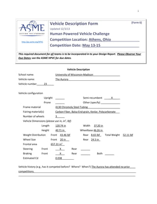
  • 1. i http://go.asme.org/HPVC Vehicle Description Form (Form 6) Updated 12/3/13 Human Powered Vehicle Challenge Competition Location: Athens, Ohio______________ Competition Date: May 13-15___________________ This required document for all teams is to be incorporated in to your Design Report. Please Observe Your Due Dates; see the ASME HPVC for due dates. Vehicle Description School name: University of Wisconsin-Madison Vehicle name: The Aurora Vehicle number_____23_____ Vehicle configuration Upright Semi-recumbent _____X__ Prone Other (specify) Frame material 4130 Chromoly Steel Tubing Fairing material(s) Carbon Fiber, Balsa End-grain, Kevlar, Polycarbonate___ Number of wheels 3 Vehicle Dimensions (please use in, in3 , lbf) Length 120.74 in Width 37.20 in Height 40.71 in_ Wheelbase 46.26 in Weight Distribution Front 43.46 lbf Rear 8.65 lbf_ Total Weight 52.11 lbf Wheel Size Front 20 in Rear 24.5 in_ Frontal area 657.31 in2 Steering Front ___X Rear Braking Front ___X Rear Both Estimated Cd 0.038 Vehicle history (e.g., has it competed before? Where? When?) The Aurora has attended no prior____ competitions. ______________________________________________________ _
  • 2. ii ASME Human Powered Vehicle Challenge 2016 East Coast Design Report University of Wisconsin-Madison The Aurora Team Members: Lucas Benish, Karl Niendorf, Kevin Rogers, Vincent Schad, Austin Cruz, Victor Markus, David Gaulke, Walter DeKock, Tyler Mattie, Ryan Sreenivasam, Elliot Moravec, Alec Onesti, Leah Stoltz, Charlie Noble, Cabell Sitter, Meghan Ziegler, Steven Berg Karl Niendorf President kniendorf@wisc.edu (920) 410-8558 Lucas Benish Chief Engineer lgbenish@wisc.edu (920) 573-287 Frank Pfefferkorn Faculty Advisor pfefferk@engr.wisc.edu (608) 263-2668
  • 3. iii
  • 4. iv Abstract The University of Wisconsin-Madison Human Powered Vehicle Team will be entering the Aurora into the 2016 ASME East Human Powered Vehicle Competition. The Aurora was designed to meet the competition’s goal of providing a viable transportation alternative to traditional automobiles. Specifically, the Aurora was designed to reach speeds of at least 45 mph, reduce the frame weight when compared to past vehicles, improve aerodynamic drag by a factor of two compared to past vehicles, and optimize energy consumption used to produce the vehicle via life cycle analysis. The Aurora features a tadpole trike configuration with rear wheel drive, a full and sealed fairing, capable of easy entry from a forward facing removable hatch, and an adjustable drivetrain such that riders ranging from 5 ft 6 in to 6 ft 6 in can easily pedal. The fairing was also manufactured with environmental concerns in mind, reducing energy consumption 72% from traditional mold making and carbon fiber layup techniques. The Aurora also features a composite roll cage fully integrated into the fairing. Thorough analysis was conducted on the frame, drivetrain and fairing systems to ensure proper safety factors were applied to avoid any potential injury in the event of a crash. Aerodynamic analysis was conducted to ensure that the drag was reduced by at least a factor of two from the previous year’s vehicle. The combination of design, analysis and vehicle testing ensures that the team will achieve its desired objectives of weight reduction, perfected aerodynamics and improved sustainability.
  • 5. v Table of Contents Abstract ..................................................... iv A. Design:................................................1 A.1 Objective ..........................................1 A.2 Prior Work .......................................1 A.2i Past Fairing Design Analysis .........1 A.2ii Past Drivetrain Design Analysis ...4 A.2iii Past Frame Design Analysis ........4 A.3 Design Specifications.........................4 A.4 Concept Development and Selection Methods..................................................6 A.4i Fairing Development.....................6 A.4ii Drivetrain Development...............7 A.4iii Frame Development....................9 A.5 Innovation ......................................10 A.5i Fairing .......................................10 A.5ii Drivetrain..................................11 B. Analysis.............................................11 B.1 RPS Analysis...................................11 B.2 Structural Analysis..........................13 B.2i Drivetrain...................................13 B.2ii Frame........................................13 B.3 Aerodynamic Analysis.....................14 B.3i Justification................................14 B.3ii Aerodynamic Theory and Design Implications.......................................16 B.3iii 3D Shape Development and Analysis.............................................19 B.4 Cost Analysis...................................21 B.5 Product Lifecycle Analysis...............22 B.5i Fairing Lifecycle Analysis ...........22 B.5ii Drivetrain Lifecycle Analysis......23 B.5iii Frame Lifecycle Analysis...........24 B.6 Dynamic Analysis ............................24 C. Testing ..............................................25 C.1 RPS testing......................................25 C.2 Developmental Testing ....................25 Carbon Fiber Material Testing...........25 Core Material Testing:.......................27 C.3 Performance Testing .......................29 D. Safety ................................................29 E. Conclusion.........................................30 Appendix.................................................... I References: .............................................. I Gantt Chart:............................................. II Matlab Calculations:.................................III
  • 6. 1 A. Design: A.1 Objective The University of Wisconsin – Madison Human Powered Vehicle Challenge (HPVC) Team designed and built The Aurora during the 2015-2016 academic year. Based upon performances in prior years, this vehicle’s primary objectives were to obtain a top speed of 45 mph, accommodate riders from 5 ft 6 in to 6 ft 6 in, reduce our team’s carbon footprint, and weigh 10% less than the team’s 2014/2015 vehicle, Del. In addition to the technical goals for The Aurora, this year the team focused on developing skills for newer members. The team held regular workshops and seminars targeted at improving the team’s technical skills and developing the next generation of engineers. Team membership doubled this year and we hope to continue to cultivate the growth and abilities of our members and the engineering community. A.2 Prior Work A.2i Past Fairing Design Analysis The UW-Madison HPVC team made a full carbon-fiber fairing for the 2014-2015 competition. This marked the third year that a full carbon fiber fairing was utilized to reduce drag and protect the rider. The geometry was reused from the 2014 vehicle since the team’s goal was to reduce the fairing’s weight and improve the manufacturing process. The fairing was one of few successes at the 2014-2015 competition; the fairing enabled our female rider to be competitive during the drag race and it also protected our male rider when the vehicle flipped and slid due to a mechanical failure in the frame’s leaning mechanism. Despite significant damage to the frame, the rider protective system was very effective since the rider was able to walk away with no injury. Figure 1 shows the 2014-2015 vehicle and fairing after the crash, revealing a worn but intact and structurally strong fairing, and a frame that is crumpled and missing wheels. Figure 1. 2015 Human Powered Vehicle Crash Photos: The 2014-2015 vehicle experienced a catastrophic crash that crumpled the frame while the fairing's RPS system withstood the impact and experienced only minor aesthetic damage (Original image).
  • 7. 2 The 2014-2015 fairing’s 2D top-view geometry was modeled around a National Advisory Committee for Aeronautics (NACA) 67-021 airfoil since it had the lowest drag at 25 mph, a common speed during the endurance race. However, at speeds of 10 and 50 mph the 66-022 airfoil experienced less drag. Despite this disparity, the 67-021 was chosen since it was significantly shorter and thus had a lower material weight [1]. The fairing was then 3D modeled around the 67-021 airfoil previously selected, and at two different heights. Fairing 1 was modeled with the airfoil placed on a plane halfway between the ground and the top of the rider’s head. Fairing 2 was modeled with the airfoil placed 6 inches below the halfway point. Figure 2 shows the slight variation between the two models. Most noticeable is the height and sharpness of the nosecone on fairing 1 versus the lower and more gradual and blunt nosecone on fairing 2. Figure 2. 2014/2015 Fairing Design Concepts: Fairing 1 and 2 were both designed around a NACA 67- 021 airfoil but featured different nose cone designs [1]. The two fairing designs were then analyzed in ANSYS fluent using a transition SST model at speeds of 25 and 50 mph. Analysis proved that fairing 2 had a lower coefficient of drag at both 25 and 50 mph and therefore was the more efficient design in normal conditions. ANSYS modeling also proved that fairing 2 had a lower static pressure over the body, smaller stagnation point, and a smaller area of low velocity behind the fairing, which suggests a smaller retarding force due to pressure differences between the front and back of the fairing [1]. Therefore, fairing 2 was selected as the geometry for the 2014-2015 fairing. The 2014-2015 fairing was manufactured using a carbon fiber “wet layup” technique developed from past years’ experiences. The first step was to develop a plug or male mold for the entire fairing so that female molds could be developed from them. The plugs were machined from a foam sheet laminate and then coated with a gel coat so they would have the proper hardness and could be sanded to a smooth finish. Fiberglass was then applied to the top of the plug segments so the inside surface would have a smooth finish. Fiberglass was used since it is inexpensive, rigid, and is resistant to temperature-induced deformation. The fiberglass segments were then gel coated, sanded, and bolted together to make the final product as seen in Figure 3 below. Figure 3. Fiberglass Female Fairing Molds: Female molds were used to ensure that the final carbon fiber product maintained the correct geometry and produced an excellent surface finish (Original image).
  • 8. 3 The final product was fabricated using a “wet” vacuum layup. This means that epoxy resin was mixed with catalyst and then painted over precut pieces of 2k twill weave carbon fiber. These “wet” pieces of carbon fiber were then placed in the female molds in alternating directions to optimize strength. It should be noted that carbon fiber is an anisotropic material, meaning that it is stronger in some directions than others. After all the carbon fiber had been placed, a cloth release film was applied so that after the epoxy had cured the final product could be ejected from the molds. The next layer in the sandwich was a thick cotton breather cloth that helped ensure there was equal pressure throughout the mold when the vacuum was applied, and to absorb some excess resin (to reduce weight). Lastly, a plastic bagging film was applied and taped to the edges of the mold so that a vacuum could be applied to remove excess epoxy from the carbon cloth. This “vacuum bagging process” and the final product can be seen in Figure 4. Figure 4. Vacuum Layup Process and Final Product: Left: Vacuum source is applied to molds to induce pressure on carbon cloth to ensure correct geometry. Right: Product halves being seamed together (Original image). One of the most notable sections of the fairing is its composite roll-cage and rider protection system (RPS). The ASME dictates that all competing vehicles must have a roll cage that fully envelops the rider so they would be fully protected in case of a crash. The ASME also mandates that this roll cage undergo a static load test as described: “A load of 2670 N shall be applied to the top of the roll bar, directed downward and aft at an angle of 12° from the vertical…. The maximum elastic deformation must be less than 5.1 cm…. A load of 1330 N shall be applied horizontally to the side of the roll bar at shoulder height…. The elastic deformation must be less than 3.8 cm [2].” The 2014/2015 roll cage consisted of a sandwich of four layers of carbon fiber oriented in 45 degree increments, a layer of ⅜ in. plastic honeycomb, four more layers of carbon fiber, and then a layer of 2k plain weave Kevlar. Kevlar was used as the final layer since it is more ductile than carbon fiber and, in the case of a sudden impact, would help to distribute the load throughout the entire roll cage and avoid any delamination at stress points. However, Kevlar is much heavier than carbon fiber and using only one layer optimizes the strength and ductility of the roll cage with little additional weight. The manufacturing techniques used to fabricate the 2014-2015 fairing were effective and simple, but they had one major flaw: they were made with a liquid two-part epoxy. The main concern with utilizing a liquid epoxy is its cure time or “pot life”. Typically, most two-part epoxies begin curing one hour after mixing, meaning that to produce a strong product, the layup and vacuum bagging must be completed within the allotted time. This is a huge challenge since the final product is often large and complicated. Because a “wet layup” is literally a race with
  • 9. 4 time, the final product tends to have problems that could otherwise be avoided, like waviness in the carbon matrix and incorrect fiber orientation. A wet layup is also riskier since it is not possible to reuse the carbon fiber if the layup does not go as planned. Depending on the size of the part, discarded material could mean a potential loss of $3,000-$4,000. For these reasons, the 2015-2016 fairing will be using prepreg or “dry carbon” so that the pieces can be laid out perfectly with no time limitations, and then be cured with heat. The past year’s vehicle also experienced issues with the windshield manufacturing. A ⅛ in. polycarbonate sheet was cut, bent, and then epoxied in place in the fairing. The bending stresses from the polycarbonate caused the hatch to deform over time, leaving gaps, which contributed to drag, in an otherwise flawless fairing. To avoid this issue for the 2015-2016 fairing, the team is strongly considering vacuum molding the windshield. The polycarbonate windshield would be heated and then formed around a mold so that when it returns to room temperature there will be no residual stresses, and thus no deformation. A.2ii Past Drivetrain Design Analysis Last year’s drivetrain had some key features that needed to be analyzed. One interesting feature was the four-bar linkage. Last year’s vehicle also had an internally geared hub. The four-bar linkage was incorporated in order to make the bike easier to adjust for the sizes of different riders. Having the bike be adjustable without moving the seat usually requires lengthening or shortening the chain. With the linkage, the pedals were shifted along the bars, and the chain was kept in the same position. While this removed the need to change chain length, the mechanism to release and fix the pedals in position on the bar was difficult to operate. The linkage also developed timing issues where the two crank arms became desynchronized. While the timing issue would be easily fixed with a second ‘timing’ chain, the pedal adjustment might be more difficult to resolve. While the internally geared hub offers a somewhat more reliable drivetrain than the conventional external gears, the range of gears differs. External gears allow more options and a wide range of gears. The limited range in gears could prove troublesome when trying to reach and maintain such high speeds. A.2iii Past Frame Design Analysis As previously mentioned, last year’s frame had several disquieting issues. First, the frame was not structurally sound. During competition the frame sheared apart where the rear axle was attached. Second, the leaning system was unstable at low speeds, making the vehicle very difficult to ride. Third, using a delta configuration for the frame forced the team to use front wheel drive, which increased drivetrain complexity and decreased overall performance. The bike was hard to steer and frequently dropped the chain. A.3 Design Specifications The UW-Madison HPVC goals for the 2015-2016 vehicle are to design and produce a vehicle that balances speed and agility to optimize performance in both the drag race and the endurance obstacle course race. To be competitive in the drag race, our vehicle must be light, aerodynamic, and incorporate an efficient drive train system. Concurrently, the endurance race
  • 10. 5 demands a vehicle with a tight turn radius, and high ground clearance. The vehicle must also be able to be driven by every member of the team, meaning that the drive-train system must be adjustable for a wide range of operator heights. Due to these vehicle constraints, the fairing must have a smooth, sleek, aerodynamic shape, be lightweight, large enough to fit around all riders, and be strong enough to survive crashes and protect the rider. The goals in Error! Reference source not found. below represent the 2015-2016 specifications for the vehicle and the fairing. The drive train for the 2015-2016 bike started with very basic goals and requirements. Our number one goal was to produce a robust system to avoid the chain issues and mechanical failures that have plagued the team in past years. In addition, the top speed must be above 45 mph at an optimal cadence. It was also important to make the drivetrain easy to adjust in order to fit a wide range of riders. There are three main goals for the frame this year. First, the frame needs to provide a rigid structure for the rest of the trike to build on. This structure needs to be strong enough to avoid power loss due to flexing but also lightweight to enable increased performance. Second, the frame needs to be adjustable. Drivers come in a variety of shapes and sizes. In order for everyone to be able to participate in competition the frame will need to be adjustable. Finally, the frame must meet all requirements set forth by ASME for the competition. These requirements include maximum turn radius, braking tests, and more. Table 1: Design Goals: Goals for the 2015-2016 Human Powered Vehicle per ASME regulations [2] Speed The vehicle must be able to travel at or above 45 mph on flat ground. Ergonomics The fairing must be able to accommodate riders with heights between 67 and 78 in. Visibility The vehicle must provide the driver with a forward-facing field of view of at least 180° wide. Ground Clearance The vehicle must be able to clear a 3.15 in. speed bump. Safety Fairing must be able to withstand crashes at all rideable speeds and experience no plastic deformation or delamination. Rider Protection A load of 2670 N shall be applied to the top of the roll bar, directed downward and aft at an angle of 12° from the vertical. The maximum elastic deformation must be less than 5.1 cm. A load of 1330 N shall be applied horizontally to the side of the roll bar at shoulder height. The elastic deformation must be less than 3.8 cm. Cargo The vehicle must be able to carry a standard sized 38x33x20 cm reusable grocery bag containing items determined by the host school (mass not to exceed 5.5 kg). Vehicle Hazards All surfaces of the vehicle—both on the exterior and in the interior in the region of the driver and in the access area—must be free from sharp edges and protrusions, open tube ends, screws and other hazards. Turn Radius The vehicle must be able to turn within an 8.0 m radius.
  • 11. 6 A.4 Concept Development and Selection Methods A.4i Fairing Development Shape Determination The overall shape of the 2015-2016 fairing will be determined by two constraining geometries, the top and side view constraining sketches. The top view constraining geometry was selected by researching airfoils standardized by NACA to help determine the best geometry that reduced the force of drag. The only major contribution that the rest of the vehicle had on selecting the top view geometry was the location of the rider, in relation to the vehicle’s length, and the width of the rider and seat. The profile view geometry was based on the rider envelope that was determined from the frame design. The 2015-2016 vehicle is considerably lower than past fairings, which has allowed for a sleeker fairing design. The frame’s seat is also angled farther back than in past years, helping to reduce the frontal area of the fairing, and ultimately limit the drag. Rider Envelope In order to design a functional fairing, the designer must know the maximum size of frame and drivetrain systems to ensure that the rider is able to extort the most power from each pedaling stroke without colliding with the fairing. Therefore, a CAD rider envelope was utilized to determine this constraining geometry. Data was collected from all team members in order to find the maximum-sized human that must fit inside of the fairing; specifically, a mannequin model was created using the max height, shoulder width, leg length and sitting height. This maximum human model was then placed in a skeleton frame model to estimate the rider’s sitting position and maximum leg extension/stroke. Cross sections were then taken every 4 in. along the length of the model and liberal sketches were created on each plane to estimate where the fairing must not interfere. This model was then used while determining the constraining top and profile view geometries that ultimately defined the fairing shape. The model used in this process can be seen in Figure 5 below. Figure 5. Rider Envelope: CAD model of rider envelope with mannequin (Original image).
  • 12. 7 2D Shape Development The design of the fairing began with choosing the top view constraining geometry. NACA airfoils, specifically the NACA 6 series, were researched since they were mathematically derived to promote laminar flow at low speeds [3]. A NACA 6 series airfoil geometry is determined by the number associated with it. For example, consider the NACA 67-022 airfoil. The 6 designates it as a NACA 6 series, the 7 is the location of the minimum pressure in tenths of the chord (distance between leading and trailing edge of airfoil), and the final two digits (22), designate the maximum thickness of the airfoil in relation to the chord. In this case, the maximum thickness is 22% of the chord length. Airfoils with various length ratios were tested using ANSYS Fluent to calculate the coefficient of drag and the force of drag felt on the fairing at 17.9 m/s. All airfoils tested had length ratios of at least 60% to help force the design to have a longer sweeping nose and shorter tail section to promote laminar flow along the entire length of the fairing. The airfoils were then imported into Solidworks and scaled around the previously established rider envelope to estimate the actual size of the fairing. The airfoil sketches were then imported into ANSYS Fluent and the coefficients of drag and force of drag was calculated using a K-Epsilon model. A.4ii Drivetrain Development Gearing Let’s begin with a little background on how the calculations were done for the following section. The equation to determine speed of a bicycle is really quite simple. Rear Teeth / Front Teeth * Cadence * Circumference = Speed This equation calculates a bicycle’s speed based on the number of teeth in the rear gear, teeth in the front gear, the cadence (pedal rotations per minute), and the circumference of the drive wheel. Aurora uses a 700c wheel with a circumference of 622 mm. This equation was used in one form or another to determine the information used in this section. While a variety of gear ratios were considered, a rear cassette similar to those found on mountain bikes and hybrids was chosen. The rear cassette style was chosen because they tend to offer wider ranges than those meant for road bikes. With this decision Aurora's rear gear would have around eleven teeth in the highest gear and thirty-four in the smallest. A top speed of 45 mph is not within normal capabilities for most bikes. This deficiency is because the most efficient cadence is eighty pedal revolutions per minute. With this cadence and an eleven tooth rear gear, a 77 tooth front gear would be needed to achieve the ideal speed. Unfortunately, 77 tooth gears are uncommon. This large gear ratio would also make it relatively difficult to get started, even in the lowest gear of our cassette with 34 teeth. Since achieving 45 mph is a challenge, a slower top speed, such as 40 miles per hour, was also analyzed. As listed in Table 2 below, the high gear ratio was calculated using the same steps as before. The low gear was calculated by using a 34 tooth gear ratio. The ratio of 42 / 20 was included as a reference because it is a common single speed gear ratio.
  • 13. 8 Table 2: Gear Ratio Selection Top Speed High Gear Ratio Low Gear Ratio 45 mph 78/11 = 7.1 78/34 = 2.3 40 mph 69/11 = 6.3 69/34 = 2.0 35 mph 60/11 = 5.5 60/34 = 1.8 30 mph 53/11 = 4.9 53/34 = 1.6 13 mph 42/20 = 2.1 42/20 = 2.1 It was found that striving for a top speed of 40 miles per hour with a cadence of 80 was the most feasible as it had a sufficiently low starting gear ratio, while still being close to the desired speed. The one major drawback with this gear ratio was there are no commonly produced front gears on the market that would achieve that high speed. Adjustability A few different ways to make the bike adjustable for different riders were explored. On most bikes, the seat is simply used to adjust for the heights of different riders. Because of the fairing, adjusting the seat was not practical. Instead, the option to improve upon the linkage system from previous years was considered. Also considered was the adjustment mechanism from the bike of two years ago which used a sliding collar on the boom. It was realized that with limited manufacturing abilities, improving the sliding collar would likely be easier to implement than the linkage. In order to improve on the sliding collar design, a keyway was added to the collar to keep the collar from rotating on the boom while pedaling. This style of adjustable collar requires different chain lengths depending on the collar’s position on the boom. To resolve this issue, a method of adjusting and tensioning the chain length must accompany the adjustable collar. Chain Tensioning A variety of methods to tension the chain were discussed. In the past, the manual tensioning configuration proved difficult and time consuming. These impediments were detrimental during competition when trying to quickly swap riders. For this reason, most of the discussions focused on automatic tensioning to eliminate the need to manually adjust the chain tension for each rider. Our solution: a simple T-slot and nut was attached to a gear. A spring attached to the T-nut allows the chain to be tensioned or loosened without any extra adjustment. Part Selection Component selection came down to two factors: price and the range in gear ratios. The HPVC budget was significantly reduced this year so the price of the components was an important factor. As a general rule of thumb, the more gears a drivetrain has, the more expensive it becomes. Nine speed drivetrains are relatively cheap, when compared to ten and eleven speed drivetrains. Eleven speed drivetrains are certainly some of the most expensive available, but they definitely do not come without benefits.
  • 14. 9 Between nine and ten speeds, there is not much of a difference in gear ranges. However, eleven speed drivetrains offer a wide range of gears. The extra gears would be extremely beneficial, especially when considering the low gear ranges on the Aurora were somewhat limited by our goal of reaching high speeds. Weighing these two factors was difficult, but it was decided it would be better to invest in an eleven speed drivetrain. If a nine or ten speed drivetrain was used, but was found not to have the range we wanted or needed, money would have been wasted buying the first drivetrain after upgrading to the eleven speed. A.4iii Frame Development The team decided on one of three main design options for the vehicle type this year. The three options were recumbent bicycle, recumbent delta trike, and recumbent tadpole trike. A decision matrix was used in order to decide which design to use. The categories examined were ease of operation (operator skill), fabrication difficulty, and design difficulty. The tadpole trike received the largest score due to its low operator skill requirement. Table 3: Vehicle Type Design Matrix (Scaled 1-5) Design Operator Skill Fabrication Difficulty Design Difficulty Total Weight 5 4 3 Recumbent Bike 1 3 3 26 Delta Trike 2 2 1 21 Tadpole Trike 3 2 2 29 The team also considered a wide variety of materials to use for the frame. Once again, a decision matrix was used to decide which material to choose. Each material was evaluated for strength, weight, fabrication, and cost. The results can be seen in Table 4 below. 4130 steel was chosen due to its ease of fabrication and high strength. Table 4: Frame Material Design Matrix (Scaled 1-5) Material Cost Fabrication Strength Weight Total Weight 3 5 4 3 4130 Steel 4 4 3 2 50 6061 Aluminum 3 1 2 2 28 Carbon Fiber 2 2 4 4 44 Docul 3 3 3 2 40 Finally, the team considered several different types of steering actuators. Based on the criteria shown below, the final decision was under-seat steering with a single control arm.
  • 15. 10 Table 5: Steering Design Matrix (Scaled 1-5) System Cost Fairing Interference Difficulty (Fab/Design) Ease of use Total Weight 2 5 3 4 Under-seat 1 3 2 3 35 Over-seat (Handlebars) 2 2 1 1 21 Direct mount to Kingpins 3 1 3 2 28 A.5 Innovation A.5i Fairing One of the biggest challenges regularly seen by student design teams is a lack of funding. Typically, fairings are the most expensive component of the vehicle. The conventional way used by other schools to manufacture their fairings is to machine molds out of tooling board for use during a carbon fiber layup. This method produces high quality, reusable molds. However, it is also very expensive. The quoted cost of the tooling board alone was nearly $10,000. Since this manufacturing option was unattainable, we decided to produce our molds by using a low-cost, recyclable cardboard laminate, laser cut to the designed shape. The cardboard was then glued together and surfaced using body putty to create plug segments. Fiberglass was then laid up on the plugs to make a female mold where our carbon fiber was laid up. Figure 6 shows the various steps taken during the manufacturing process: cutting/gluing, surfacing, and sanding/resurfacing. Figure 6. Cardboard Plug Manufacturing Fairing costs were also reduced by incorporating recycled carbon fiber donated by the Trek Bicycle Corporation. The donated carbon was precut for use on their high-end bike frames but was repurposed for our needs by laminating it together in our molds at 0/45/90-degree
  • 16. 11 orientation. In short, by switching to cardboard plugs and recycled carbon fiber we reduced the fairing’s energy consumption by 75% and reduced our manufacturing cost to ~$300. A.5ii Drivetrain 3-D Printed Crank arms One unique part of the drivetrain this year is the crank arms. These arms were 3-D printed using a carbon fiber printer made by MarkForged. The design for these crank arms was simplified to allow the printing process to be completed faster. The printer takes a model and puts layers of carbon fiber down to add stiffness to the plastic. Using fiber reinforced plastic greatly reduces part weight as well as ease of fabrication. B. Analysis B.1 RPS Analysis The fairing’s roll cage was analyzed for structural integrity by using Solidworks Finite Element Analysis to determine the maximum deflection at an applied top load of 2670 N and side load of 1330 N. The FEA was setup by first creating a new material in the Solidworks library to better represent the structural properties of our balsa/carbon fiber structure. Mechanical properties for a 120-degree C cure, unidirectional, 0/90° layup with an assumed 50% carbon and 50% balsa composite were assumed since they best fit the mechanical properties of our recycled carbon utilized [4]. Carbon fiber exhibits anisotropic behavior, creating difficulties in modeling. However, we assumed our material could be modeled as isotropic since our layup will feature 0/45/90-degree layup orientation to optimize strength in all directions. The fairing roll cage was modeled with 8 layers of carbon fiber with a 3/8-in. balsa end grain core. By comparison of this analysis and testing our recycled carbon fiber weave we will determine the final number of carbon layers. For further reference of this analysis see Figure 7. Our model was fixtured by assuming the two joints where the fairing is attached to the frame are fixed. This assumption is reasonable since the bottom attachment will be bolted to a plate included in the layup and the rear attachment will be clamped to the frame’s rear triangle. Figure 7 below shows the results of the modeling in respect to deformation and Von Mises stress. Specifically, note the locations where the fairing was fixed (across the cross bar and near the floor). Lastly, our model utilized a fine mesh to optimize the accuracy of the FEA at the expense of simulation time.
  • 17. 12 Deformation Von Mises Stress Analysis 2670 N Applied Top Load @ 12° 1330 N Applied Side Load @ Rider Shoulder Figure 7. FEA Analysis of Fairing roll cage with ASME mandated top and side loading (Original image). Table 6 shows the results of the FEA analysis. The ASME mandates that our roll cage experience a maximum deflection of 5.1 cm for the top load and 3.8 cm for the side load. Our analysis shows that the expected deformations for both the top and side load are well within our design requirements. Also, we found that the current design had a minimum factor of safety of 4.7 which, as it is a high number, is desirable. Our layup process utilizes recycled carbon fiber and techniques designed specifically for our use and, therefore, it is relatively untested and undocumented. Because of this expectation of variability between our design and the final product, a large factor of safety is preferable to account for possible manufacturing error. Table 6: FEA roll cage analysis results. Top Load (2670 N) Side Load (1330 N) Max Deformation (mm) 2.8024 0.62284 Max Von Mises Stress (MPa) 127.84 21.9 Min Factor of Safety 4.7 27
  • 18. 13 B.2 Structural Analysis B.2i Drivetrain One of the most important parts of Aurora’s drivetrain is the sliding bottom bracket. Because of the drivetrain’s importance, ANSYS testing was performed on it to help determine how it would hold up to stresses. The hole that would be used to fix the bottom bracket to the frame was assumed to be the fixed point. A force of 607 lb was used because it was assumed the force a rider could apply to the pedals would be equivalent to roughly four times the rider’s weight. Figure 8 below shows the forces applied and the result of the simulation. The maximum Equivalent Stress is nearly 2 ksi (thousand pounds per square inch). As the maximum allowable stress for 6061 Extruded aluminum is 35 ksi, there is a significant factor of safety of ~19. Figure 8. Left: The forces applied in testing. Right: The results of the testing. B.2ii Frame In order to determine possible frame failures, the team used Solidworks FEA package to perform stress analysis. Stress analysis was performed on the boom in order to make sure there was no excessive deformation from pedal loading. The frame was modeled as fixed at the cross-member and drop outs, whereas the boom was treated as fixed on only one end. The pedaling force was modeled as a 250 lb force towards the front of the vehicle. Estimates of average pedal forces range from around 150 to 200 lb. The analysis shows the minimum factor of safety to be around 2.5. This model is quite conservative, as the actual load will be applied further down.
  • 19. 14 Figure 9. FEA Analysis of Frame Boom In addition, in consideration of the load from rider and frame weight, a stress analysis was performed on the entire frame. The frame was fixed at the king pins and dropouts with 250 lb loads applied at each arrow as seen in Figure 10. This loading was needed to overestimate the amount of force that would actually be applied by the rider’s pedaling and weight. The minimum factor of safety was found to be around 6. The team decided to use a large factor of safety since our team has not designed a tadpole trike in recent history, and because a large factor of safety will help account for errors or unforeseen loading factors. Figure 10. FEA Analysis of Frame Weldment B.3 Aerodynamic Analysis B.3i Justification The 2015-2016 UW-Madison HPVC team performed an analysis in order to justify the investment of time and money in designing and fabricating an aerodynamic fairing. The two largest efficiency losses on a human powered vehicle are rolling resistance losses and aerodynamic drag losses. Rolling resistance is defined as the loss due to tire deflection and bearing friction. Conversely, aerodynamic drag is defined as the fluid drag force that acts on any moving solid body in the direction of the fluid freestream flow. Therefore, pressure differences and frictional forces acting on the vehicle can cause substantial losses. Often, aerodynamic drag accounts for 50-75% of the total retarding force experienced by a land vehicle [5].
  • 20. 15 The equation for calculating rolling resistance, Equation 1 FRolling Resistance= (Crr1+Crr2V) * W Where: FRolling Resistance is the retarding force felt on the vehicle due only to rolling losses like tire deformation, and bearing friction. Crr1 is the coefficient of loss due tire deformation, which is 0.005 for a typical bike tire. Crr2 is the coefficient of loss due to wheel configuration, which is 0.00066 (mph-1) for a typical 3-wheeled vehicle. W is the projected weight of the rider and vehicle, which is 235 lb. V is the velocity of the vehicle with respect to the road surface. This equation shows that power loss is linearly proportional to vehicle speed since all resistance criteria explained above are multiplied against a velocity that is only factored to the power of 1. It is also important to note that the only way to optimize the power loss due to rolling resistance is to lower the vehicle weight since Crr1 and Crr2 are both tabulated values that have already been optimized. Therefore, the best way to reduce rolling resistance is by lowering the vehicle weight. The equation for aerodynamic drag is given by, Equation 2 FDrag=½CDAρV2 Where: FDrag is the retarding force felt on the vehicle due only to air resistance. CDA is an estimated frontal drag area of 0.5621 m2 for an un-faired vehicle. ρ is the density of air at standard temperature and pressure, 1.2 kg/m3 . V is the velocity of the vehicle with respect to the road surface. This equation shows that power loss is exponentially proportional to vehicle speed since the independent variable, velocity, is to the second power. In order to optimize the aerodynamic drag, either the coefficient of drag (CD) or the frontal area (A) must be reduced. Density of the air (ρ) is a property of the environment and thus cannot be reduced in order to optimize the power loss. The frontal area is largely determined by the rider size and the frame design. This means that the best way for the designer to reduce drag is by reducing the coefficient of drag by designing a geometry that optimizes the flow of air around the vehicle. Therefore, the two best ways to improve the speed performance of the vehicle are to reduce vehicle weight and reduce the coefficient of drag. Since the coefficient of drag is multiplied by velocity to the second power, whereas vehicle weight is multiplied by velocity only to the first power, the best overall way to reduce power loss is to augment the coefficient of drag for the vehicle. Assuming that the CDA of a faired vehicle is 0.019 m2 , the power loss due to aerodynamic drag and rolling resistance with a faired and unfaired vehicle is outlined in Figure 11 below.
  • 21. 16 Figure 11. Power Loss vs. Velocity: Power losses due to air resistance surpass losses from rolling resistance at approximately 10 mph (Original image). As shown in the graph above, aerodynamic drag of a vehicle without a fairing becomes the dominating loss at approximately 10 mph since that is the point on the x-axis where the curve corresponding to drag surpasses the line relating to rolling losses. Therefore, providing a fairing to reduce aerodynamic drag is critical in order to prevent power loss since the vehicle goal speed is 45 mph. B.3ii Aerodynamic Theory and Design Implications When designing an aerodynamic vehicle, it is important to fully understand the mechanisms that induce and constitute aerodynamic drag in order to minimize their effects. The first mechanism is pure friction drag, where the force is actuated by shear stress between the object’s surface and the fluid that it is moving relative to the body. Friction drag is proportional to the size of the “wetted area,” where air is exposed and flowing [6]. The size of the friction drag force is also determined by whether the air flow is laminar or turbulent. Laminar flow is when the fluid moves in smooth layers, whereas turbulent flow experiences random and chaotic particle movement due to random three dimensional velocity changes as seen in Figure 12 [6]. Whether the flow is laminar or turbulent is determined largely by the fluid’s speed but is also affected by the surface finish the fluid is acting upon. Imperfections in the finish will trip a boundary layer and cause the fluid to start flowing turbulently, starting at that point down the length of the entire fairing. Therefore, one of the key ways to reduce drag is to avoid inefficient turbulent flow by ensuring that the final product has an excellent surface finish [5].
  • 22. 17 Figure 12. Fluid Flow Types: The differences in particle movement between laminar and turbulent flow [7]. The second mechanism of drag is pure pressure drag, where the retarding force is from the pressure difference between the air before and after the fairing [6]. High pressure accumulates at the nose of the fairing due to its movement through air, compressing the fluid due to air’s stagnant inertia, or resistance to instantaneous changes in velocity. This high pressure point is similar to snow accumulating on the front of a shovel as it is pushed forward. At first the snow accumulates on the shovel but as it moves forward some is stacked in front and the rest is pushed to the sides. The low pressure behind the fairing is due to separation of the flow around the vehicle. Since the vehicle is moving forward, the space where the tail end of the fairing used to be is suddenly vacant. This newly opened space acts as a vacuum and low pressure spot as air collapses into the void. Minimizing the pressure difference between the front and back is incredibly important since the direction of a pressure induced force is from the point of high pressure to the point of low pressure. This pressure force applied on a fairing, as outlined in Figure 13, shows that reducing a pressure force is essential since the force vector’s direction will always be the opposite of the vehicle's velocity vector. Figure 13. Pure Pressure Drag: Relationship between pressure contours and drag (Original image). From this realization, the fairing can be designed to minimize the pressure between these two points. To reduce the pressure at the nose cone, the initial frontal area needs to be reduced by increasing the sharpness. It is important to note that there must be a balance between the nose
  • 23. 18 cone’s effectiveness and the vehicle's overall weight. Increasing the nose cone length and decreasing its profile view angle may improve aerodynamics but it will come at the expense of increased weight and the drivetrain efficiency. To raise the pressure behind the fairing the designer must try to avoid airflow separation from the fairing surface since separation is what causes the vacuum-like effects on the air behind the vehicle [5]. The best way to avoid airflow separation is to include airfoil geometry, common in aeronautical design, in the fairing since they feature a sharp, swept tail section that is mathematically derived to avoid separation. The results of the ANSYS Fluent testing can be seen in Table 7 below. Table 7: Pure Pressure Drag: Relationship between pressure contours and drag (Original image). Airfoil Length (m) 17.9 m/s (40 mph) CdA (m2 ) Force Drag (N) NACA 0018 3.675379999 0.025635764 5.161325 NACA 0021 3.369310001 0.031450858 6.180316 NACA 63-018 3.800602001 0.056847142 11.150677 NACA 66-018 3.618229999 0.072946304 14.2883 NACA 66-021 3.230626001 0.042915322 8.41829 NACA 66-022 3.150361999 0.056243965 11.040991 NACA 66-023 3.06705 0.078232216 15.4668807 NACA 66-024 3.00355 0.058710709 11.512623 NACA 67-021 3.126486 0.065421452 12.572972 NACA 67-022 3.14325 0.046082698 9.0184917 NACA 67-023 3.00355 0.082382042 16.192101 NACA 67-024 2.968498 0.088432688 17.405212 The 2015-2016 fairing was selected by weighing fairing length, width, force drag, and coefficient of drag. The best airfoil was determined by using a design matrix that weighted the criteria above in order of importance. Fairing length was determined to be the most important factor since size is such an important constraint in manufacturing practicality. Force of drag and Cd were weighted second and third highest respectively, since they directly relate to the effectiveness of the design. Lastly, fairing width was given the lowest priority since there was already limited distinction between the airfoils in that category. The results of the design matrix can be seen in Table 8 below.
  • 24. 19 Table 8: Top View Geometry Matrix: weighted and normalized matrix used to determine constraining top-view geometry (Original data). As Table 8 shows above, the 66-021 and 67-022 airfoils tied for the highest score. Ultimately the 67-022 airfoil was chosen as the 2015-2016 constraining geometry since it had a shorter length, which was the highest weighted constraint, and assumed that the associated weight loss would outweigh the lower drag of the 66-021 airfoil. Figure 14 below, shows a NACA 67-022 airfoil ANSYS fluent simulation. Note the increased velocity near the sidewalls of the airfoil, and the slower air before and after the fairing resulting from the high pressure point and the fairing’s wake. Figure 14. NACA 67-022 Airfoil: Velocity streamline of NACA 67-022 airfoil (Original image). B.3iii 3D Shape Development and Analysis After the Plane View 2D geometry had been chosen, the 3D geometry was designed using a statistical approach. Four different profile geometries were sketched as a guideline for the side view shape when the geometry was created using the loft function. From a designer’s standpoint, there are two main features that can be designed creatively to optimize aeronautics: windshield type and nosecone shape. The two main types of windshields found on HPVs are bubble canopies, as seen in fairing V1 in Figure 15, and swept canopies as seen in fairing V2 in Figure 15 [5]. Three different nosecone styles were used to test their independent effects on drag. The nosecone featured in fairings V1 and V3 was based around a 67-022 airfoil, the same as the previously chosen 2D geometry. This airfoil was chosen to reduce fairing length, and tries to create geometry with a true conical nose section. Since the side and top view geometries are the same, the rotated feature will be much rounder than if a different airfoil was chosen, creating a
  • 25. 20 torpedo-like geometry. The second nosecone, featured in fairing V2, was based on the same principle used when designing fairings V1 and V3, except a NACA 0018 airfoil was used instead since it had the lowest coefficient of drag of all the tested 2D geometries. Notice particularly how much sharper V2’s nosecone is compared to that of V1 and V3. The last nosecone created was an experiment to try and reduce any lift that the fairing might create. Eliminating lift is important because lift reduces the normal force felt at the wheel on the ground, reducing traction and thus losing efficiency. Creating a downforce from the vehicle’s body moving through the air is common in the vehicle industry and is most often created using a spoiler or wing [5]. The downforce in fairing V4 was created by lowering the nosecone closer to the ground. As air approaches the vehicle it is either forced under or over the fairing body. Air that goes under the vehicle experiences a pressure increase due to being compressed between the wedge-like shape of the fairing and the ground. This high pressure mass under the fairing then creates an upward force. In order to reduce lift, the nosecone was lowered so that less air could flow under the vehicle to create the high pressure mass. Side View Front View Fairing V1 Fairing V2 Fairing V3
  • 26. 21 Fairing V4 Figure 15. Fairing Views: Side and front views of considered fairing designs (Original image). *Not in same scale The four different fairings were then imported into ANSYS fluent and their coefficients of drag, force of drag, and coefficient of lift were calculated using a K-Epsilon model at 10 mph and 40 mph. The models were also tested with a 45 degree, 40 mph crosswind to simulate each vehicle’s response to environmental winds to ensure that the applied force wouldn’t affect steering or cause tipping. Figure 16 shows the air vortices from the crosswind analysis of fairing V2. The helical path-lines represent the turbulent wake that is produced due to flow separation. Figure 16. Fairing V2 Crosswind Response: Transient path lines over fairing V2 in 45-degree crosswind (Original image). The results of the ANSYS testing can be seen in Table 9. Numerical results were then weighted and normalized in a design matrix to choose the final fairing geometry. The weight of each category was balanced so that each general category (coefficient of drag, force drag, and coefficient of lift) would have the same overall weight. From this analysis, model V2 was determined to be the best geometry for the 2015-2016 fairing. Table 9: 3D Model Design Matrix: Weighted and normalized CFD data used to determine 3D geometry (Original data) B.4 Cost Analysis When designing a new product, it is important to analyze the cost. Not just the cost of one bike, but the cost of an entire production run. This type of information can then be used to estimate a price that consumers will pay for the product. In order to estimate the cost of
  • 27. 22 producing the vehicle, costs were separated depending on if they were something which needed to be purchased for each vehicle produced, such as drivetrain components, or something which could be used to make multiple bikes, such as molds for carbon fiber layup. Labor was assumed to be around $20 an hour on average. The carbon fiber for Aurora was donated by Trek Bicycle Corporation because it was unusable for their applications. For this reason, it was estimated that a deal could be made with them or other companies to buy ‘recycled’ carbon fiber at 20% of the normal cost. Table 10 below outlines the cost of one vehicle by breaking it into the different major components. Table 10: Cost break down for one vehicle by the major components. Section Materials Labor(Hours) Combined Drivetrain $2000 16 $2320 Brake Lights $250 8 $410 Programming 26 $820 Brakes $100 2 $140 Safety and Comfort $150 10 $350 Fairing $300 75 $1700 Molds $1400 450 $10400 Frame $250 30 $850 Total $4350 617 $16690 Estimating the cost to create one vehicle enabled the team to estimate the cost of producing 200. The cost of electricity to run metal working machinery was included in the overhead costs, as well as rent for a warehouse. Table 11: Cost break down for a 200 bike production Material Costs $531,000.00 Labor Costs $601,200.00 Overhead Costs $800,000.00 Tooling Costs $900,000.00 Capital Investments $200,000.00 Total Costs $3,032,200.00 Cost Per Vehicle $15,161.00 B.5 Product Lifecycle Analysis B.5i Fairing Lifecycle Analysis The following life cycle analysis (LCA) in Table 12 was calculated with a focus on the energy use to produce the raw materials used in the vehicle. Note that environmental friendliness was considered when implementing recycled carbon fiber for the fairing and recycled cardboard for the plug/form (instead of traditional polystyrene foam board). These two changes account for
  • 28. 23 a 74.81% reduction in energy usage to produce the same product. For more information on the cardboard mold making process utilized refer to section A.5i Fairing. Table 12. Fairing LCA Results: Life Cycle Analysis Conducted on the Fairing and Fairing Molds Material Energy Use Amount Per Vehicle Total Energy Use Materials Used on Fairing Carbon Fiber (Recycled) 30 MJ/kg [8] 22.075 662.25 MJ Carbon Fiber (Non- recycled)* 183 MJ/kg [9] 22.075 4039.73 MJ Balsa End-Grain Core Material 4.1868 MJ/kg [10] 3.89 kg 16.29 MJ Materials Used on Mold/Plug Cardboard 20.17 MJ/kg [11] 1872.4 kg 37766.308 MJ Polystyrene Foam Board* 59.03 MJ/kg [12] 2826.93 kg 166873.68 MJ Fiberglass 13 MJ/kg [9] 174.52 kg 2268.76 MJ Vinyl Ester Resin 76 MJ/kg [9] 36.29 kg 2758.04 MJ Polyester Gel Coat 63 MJ/kg [9] 18.14 kg 1142.82 MJ Legacy Energy Use: 177,099.32 MJ Optimized Energy Use: 44,614.47 MJ *For Comparison Analysis (Vehicle only utilized recycled carbon and did not use any foam board) Reduction in energy use: 177099.32[MJ] − 44614[MJ] 177099.32 [MJ] ∗ 100% = 74.81% Reduction B.5ii Drivetrain Lifecycle Analysis The LCA for the drivetrain, as shown in Table 13, was calculated using a method similar to that for the Fairing LCA, focusing on energy required to produce the raw materials. To estimate the energy needed to manufacture each component of the drivetrain, the weight of the component and the energy needed to manufacture the main material of each component (in MJ/kg) was used to calculate the total energy to manufacture a single vehicle. Table 13: Life Cycle Analysis Conducted on the Drivetrain Components Component Material Mass (kg) Energy Use (MJ/kg) Energy (MJ) Chain Nickel 0.777 200[ 16] 155.4 Cassette 4130 Steel 0.394 40[ 16] 15.76 Rear Derailleur Aluminum 0.265 320[ 16] 84.8 Grip Plastics 0.144 90[ 16] 12.96 Rims Aluminum Alloy 1 320[ 16] 320 Hubs Steel 0.325 40[ 16] 13 Crank Arms Plastic 0.5 90[ 16] 45
  • 29. 24 Pedals Aluminum 0.3 320[ 16] 96 Brakes Steel 0.5 320[ 16] 160 Total 902.92 B.5iii Frame Lifecycle Analysis The life cycle analysis for the frame includes only the energy of formation for the materials used in the production of the frame. This excludes transportation and manufacturing energy usage. Table 14: Life Cycle Analysis Conducted on the Frame Components Component Material Mass (kg) Energy Use (MJ/kg) Energy (MJ) Frame Weldment 4130 Steel 1.14 35 [13] 39.9 B.6 Dynamic Analysis The team also performed calculations using Matlab to find maximum braking speeds, maximum cornering speeds, and minimum turning radius. The turn radius was found to be 15 ft. The maximum deceleration before the rear wheel would lift off the ground is approximately 0.73 lateral g’s. See appendix for calculations. Next, the team made sure that the vehicle would slip before rolling over in a turn or during braking. The maximum lateral acceleration in a turn was found to be 0.64 Gs. A coefficient of friction of 0.55 was used during analysis assuming friction between rubber and dry pavement. Lastly, the ideal Ackermann steering ratio was calculated and compared with the frame’s actual steering compensation as seen below in Figure 17. An ideal Ackermann steering compensation means there is zero slippage when cornering. This equates to zero power loss from slippage in corners. Having a close to ideal steering compensation at small steering angles means that the vehicle will have minimal power loss in high speed cornering. Figure 17. Ackermann Steering Compensation Comparison
  • 30. 25 C. Testing C.1 RPS testing In order to accurately test the roll cage per the ASME competition specifications, a smith weightlifting machine was used to apply the load. To measure deflection, an HD camera was focused on a marked point along the top and sides of the roll cage, and video was taken. The video was then analyzed using a program called LoggerPro® that has the ability to track an object’s position through time. LoggerPro was then able then to record the deflection through time as load was increased by adding weight. Figure 18 shows the testing setup and data collection hardware. Figure 18. Roll Cage Testing Method: Setup of the roll cage testing method. A static load is applied via the guided bar bell and data is collected using the HD camera focused on the top of the roll cage (Original image). C.2 Developmental Testing Carbon Fiber Material Testing Past composite fairings utilized a “wet” layup in which epoxy resin is applied to the carbon fiber weave before it is applied to the mold. A vacuum source is then used to withdraw the excess epoxy and lower the weight of the part. The advantage of this manufacturing process is that it can be done at room temperature on full-size molds; however, the vacuum used to remove the excess epoxy resin is not 100% effective and the part is often heavier than it needs to be. To remove this excess weight, the 2015-2016 fairing will be constructed using pre- impregnated carbon fiber. Pre-impregnated carbon fiber (prepreg) is manufactured with the epoxy resin already mixed with the carbon strands, maintaining the perfect resin-carbon ratio and optimizing weight. Prepreg is then cured by using heat as the catalyst to activate the chemical reactions in the epoxy that hold the carbon fibers together. The only disadvantage to this material is that it is very expensive, even when compared to other variants of carbon fiber. Fortunately, the Trek Bicycle Corporation donated to the team scrap pieces of prepreg carbon fiber from their manufacturing facility. This practice of recycling scrap carbon for the 2015-2016 fairing is environmentally friendly, sustainable, and cost effective since industry would otherwise be forced to throw it out or invest in the energy intensive process of recycling it.
  • 31. 26 Since scrap pieces were being used instead of larger, stronger pieces the carbon was subject to tensile testing to ensure rider safety during competition. To prepare the test pieces the prepreg carbon was laid up in a 4-layer lattice where short pieces were overlapped to optimize bonding strength. The carbon was then vacuum-bagged against a machined aluminum plate and cured in the oven at 250°F for an hour. The nearly finished sample was then removed from the vacuum bag and tensile testing pieces were cut using a CNC water jet. The layup process and the final tensile testing pieces can be seen in Figure 19 below. Figure 19. Prepreg Test Piece: Left: Carbon layup curing in the oven. Right: Tensile test pieces cut with CNC water jet (Original image). The test pieces were then tensile tested until failure using a Syntech tensile testing machine where their stress (σ), strain (ε) was recorded and ultimate strength (Ut) calculated. The ultimate strength was then compared against common industry accepted values. Table 15 below summarizes our results. It was concluded that in the 0-degree orientation our samples were well within our targeted ultimate strength of 600 MPa. However, the 0-degree orientation also had a large standard deviation, introducing a large degree of uncertainty of the material’s true strength. In the +90-degree orientation our values were significantly below our target value but did have a lower standard deviation. Since tensile testing showed that our results were subject to a high degree of variability, a very conservative approach was taken when choosing the number of layers and fairing wall thickness. Assuming a worst case scenario, 60% more layers of carbon fiber must be utilized since: 570[𝑀𝑃𝑎] 350[𝑀𝑃𝑎] = 1.6 = 160% Therefore, our total wall thickness must be 160% of the value found from the FEA analysis of the fairing when utilizing the “black aluminum” approach. The result: ~12 layers of carbon fiber are required. Table 15: Tensile Testing Results and Fiber Orientation Data (Original Image) Fiber Orientation 0 Degrees +90 Degrees Average Value Accepted Value [14] Average Value Accepted Value [14] Ultimate Strength (MPa) 787.4224 600 355.2865 570 Standard Deviation (MPa) 138.59 79.38
  • 32. 27 Core Material Testing: The core material in a composite structure is used to provide rigidity and reinforce the carbon fiber. Adding strength is especially important when designing safety features, such as the roll cage. It is also important to use core materials in vulnerable areas with complex geometry, like the nose cone and hatch edges, to avoid fracturing in case of a crash. The core materials for the 2015-2016 vehicle were chosen by conducting material testing on several different commercially available materials. The testing samples were prepared by sandwiching them between layers of 2x2 twill weave carbon fiber and then vacuum bagging them to ensure there were no air bubbles between the carbon and the core material. This method ensured that a quality sample with the optimal strength was produced. After the carbon-core samples had fully cured they were removed from the vacuum bagging materials and trimmed to an equal size of 4. in by 6 in. These samples were then submitted to three-point bending using a Syntech tensile testing machine with a computer actuating a California Bearing Ratio (CBR) test (as suggested by the lab supervisor). The Syntech machine can accurately measure the applied force as well as the crosshead displacement. The samples were placed on a rigid jig so that the crosshead could be lowered directly onto the center to conduct three point bending as seen in Figure 20. Figure 20. Three Point Bending: Syntech machine demonstrating a three-point bending test (Original image). The data collected from the recorded force and crosshead position was then used to estimate the bending modulus (rigidity) of each sample and then be normalized with the sample’s weight to find the strongest material for its weight. This method is defined in the equation below. The equation for calculating the bending modulus, Equation 3 E_bend=(L3 *F)/(4*W*H3 *d) [15] Where: Ebend is the bending modulus of the material or the measured rigidity. L is beam length of the core sample, which was 240 mm. F is the applied force of the crosshead in newtons. W is the beam width of the core sample, which was 101.6 mm. H is the thickness of the beam, which varied between the samples. d is the measured deflection of the crosshead at the load point in meters. This equation relates a material’s response to an applied force with its geometric shape. The L3 /(4*W) term in the equation represents the area moment of inertia of the beam while the
  • 33. 28 F/(H3 *D) term represents the deflection based off of the elastic beam theory. From the equation above we can conclude the higher the value for Ebend the more rigid, or resistant to deflection, the material is. After all of the Ebend values had been calculated for each of the samples they were compiled in Table 16. Table 16 relates the ultimate strength (force at which failure occurred), rigidity (Ebend), and mass of each sample to determine the best core material for each application. The fairing has three different sections that require different levels of reinforcement: the nosecone, the hatch, and the roll cage. The nosecone features tight geometry, so a core material that is easily formed to complex shapes is necessary. The nosecone is also the farthest point away from a frame attachment, and thus it needs to be light in order to reduce the movement felt by the frame-fairing joint. Therefore, a lower density core is desirable. Lastly, the nosecone must be able to handle reasonable impacts in case of a minor collision or if the vehicle tips forward during a rapid brake. This means that the core material must have an adequate ultimate strength and bending modulus. Based off of the data in Table 16, the ¼” 3.0 lb/ft3 Nomex Honeycomb is the best fit since it is easily formed, lightweight, and responds well to impact. The hatch requires a rigid core that can hold its own shape and provide a clean and sharp edge to ensure a tight fit between the canopy and base sections. The hatch also must be able to survive a rollover crash, and thus a higher ultimate strength and impact resistance is necessary. Core weight it also very important since the hatch portion of the fairing is large, and thus a low density core is required. Based on these criteria and the data in Table 16, ¼ in. balsa end grain wood is the best choice since it is low weight, durable, and strong. The last fairing section, the roll cage, requires the highest amount of strength and ductility since it must absorb any impacts and hold its shape so that the rider avoids injury. Due to these concerns, weight is less of a factor for this section. The best way to provide a higher strength section that can handle sudden impacts is to choose a core material that has an elastic failure type. An elastic failure means that instead of cracking or breaking the material bends or crushes to absorb the energy. Table 16 shows two different materials that exhibited the desirable elastic failure; however, only the carbon core plastic honeycomb has a strength comparable to other tested materials. Unfortunately, correspondence with the manufacturer proved that the plastic honeycomb would not be able to survive the high temperatures of the resin curing process. Despite the data showing that the plastic honeycomb was the best option for the roll- cage, it was decided that the roll cage would constructed with a 3/8 in. balsa end grain wood since it showed a relatively high strength to weight ratio and could sustain the high temperatures needed to cure the carbon fiber. Table 16: Material Testing Results: comparison between core samples of their ultimate strength, bending modulus and failure type (Original data).
  • 34. 29 C.3 Performance Testing The team plans to test the minimum turn radius and maximum deceleration after the vehicle has been fully assembled. Max deceleration will be tested by stopping as quickly possible from 20 mph. The time will be recorded and used to calculate average deceleration. The minimum turn radius will be tested by measuring the smallest turn radius that the vehicle can achieve at various speeds without tipping. D. Safety Although achieving high speeds and a high place on the podium is important to the UW Human Powered Vehicle team, safety is our highest priority. We have introduced four features to help protect the rider to the best of our abilities: 180-degree view windscreen, blind spot detection system, hydraulic disc brakes, and a reinforced carbon fiber roll cage. With these four systems we hope to eliminate any chance of injury to our rider. A clear field of view is imperative for the safety of the team and the other competitors. A collision between vehicles can easily be avoided if vehicles can clearly see each other. A 180- degree windscreen allows the rider to see vehicles to the direct left and right of them. In the past, our vehicles have had a narrow field of view which was somewhat unavoidable due to the shape of the fairing. This year, the fairing’s shape allows us to implement a wraparound windscreen without sacrificing the strength of the carbon fiber. As anyone who has driven a car may have realized, even with a large windscreen it is still possible to forget to check one’s blind spot. In order to protect the operator from this hazard, we have implemented a blind spot detection system. The system utilizes ultrasonic sensors to detect vehicles in over-the-shoulder blind spots When a vehicle is detected, yellow LEDs flash inside the vehicle. While this feature protects the rider from merging into other vehicles, it does not prevent other vehicles from merging into our vehicle. It is still imperative that the vehicle is able to stop quickly. To give the operator the shortest possible stopping distance, the vehicle is equipped with hydraulic disc brakes on the front wheels for optimum stopping power. Unlike traditional mechanical brakes, hydraulic brakes require less force to produce the same braking action. While we hope to always be in front of all the other vehicles, it is important to be prepared to stop if a vehicle in front of ours makes an unexpected move. We hope to prevent collisions by implementing a high quality brakes, a blind spot detection system, and a 180-degree view windscreen, collisions are always possible. In the unlikely event of a collision, the rider will be protected by a reinforced carbon fiber roll cage. The importance of a roll cage was shown to us first hand at last year’s competition. Our roll cage was the only thing between our rider and the pavement during a crash caused by an unfortunate malfunction in the vehicle’s axle. Unlikely situations such as this cannot be prevented, making the roll cage the most important safety feature. While the designs of these safety features have been explained in great length earlier in the report, the most important outcome is that the rider will be safe in any situation the competition presents.
  • 35. 30 E. Conclusion The University of Wisconsin Human Powered Vehicle team and the ASME Human Powered Vehicle Competition share a kindred goal of promoting a sustainable and practical alternative mode of transportation. In order to achieve this fundamental goal, our team began by creating goals for each subgroup to achieve. Since our vehicle was not being completely finished by the due date of this design report, we are unable to produce quantitative results at this time. However, the following tables present our goals and how we designed the Aurora to fulfill them. Table 17: Summary of Vehicle Fairing Lightweight Utilizing the strength to weight ratio of carbon fiber, the fairing is as lightweight as possible without sacrificing safety. Safe Using a Kevlar roll cage, our fairing was designed to withstand a top load of 2670 N and a side load of 1330 N. Aerodynamic Using computer aided optimization, our fairing is as aerodynamic as possible while fulfilling rider envelope requirements. Accommodating By taking measurements of all the team members, the fairing is tailor made to accommodate anyone who chooses to ride. Drive Train Robust By creating a simple yet effective drivetrain, there are less areas where a problem could arise. Adjustable Using a frame-integrated sliding collar which the drive train rides on, the drive train can be adjusted to the optimal length for each rider. Speeds Upwards of 45mph The gear ratios used will deliver a speed of 45 mph at an average cadence of 80 rpm. Frame Light Our frame weighs in at 10.25 pounds, 2 pounds less than our frame in last year’s competition. Rigid Using computer aided analysis, our frame was designed to withstand all expected forces with a 2.5 factor of safety. Adjustable By integrating the drive train’s sliding collar directly into the frame’s boom, the frame accommodates all of the riders on the team. As stated earlier, due to the time requirements of the design report, our vehicle was not able to be fully evaluated with respect to the goals and requirements set by our team. When the vehicle is completed, we plan to evaluate the effectiveness of the vehicle by test riding it in a competition-similar environment as well as performing strength and deformation tests on the frame and fairing. As with any design, the Aurora’s design has room for improvement. The recommendations we have for future revisions of the vehicle are as follows: Create the fairing molds using machine foam plugs instead of cardboard, use a tilting frame to minimize turn radius, and advance the Gantt chart in order to complete the vehicle in time for full testing and analysis before the due date of the design report.
  • 36. I Appendix References: [1] A. Ebertowski, "2013-14 Human Powered Vehicle Fairing Design and Fabrication," 2013. [2] "Rules For The 2016 Human Powered Vehicle Challenge," 20 September 2015. [Online]. Available: https://community.asme.org/hpvc/m/default.aspx#_ga=1.28322364.1264095757.1445208935. [3] P. Marzocca, "The NACA Airfoil Series," 18 September 2003. [Online]. Available: http://people.clarkson.edu/~pmarzocc/AE429/The%20NACA%20airfoil%20series.pdf. [Accessed 26 October 2015]. [4] "Performance Composites," July 2009. [Online]. Available: http://www.performance- composites.com/carbonfibre/mechanicalproperties_2.asp. [Accessed 8 April 2016]. [5] G. Tamai, The Leading Edge: Aerodynamic Design of Ultra-streamlined Land Vehicles, Cambridge: Bentley Publishers, 1999. [6] P. J. Pritchard, Fox and McDonald, Fluid Mechanics, United States of America: John Wiley and Sons, 2011. [7] "Snow and Avalanche Glossary," [Online]. Available: http://www.avalanche- center.org/Education/glossary/laminar-flow.php. [Accessed 11 December 2015]. [8] R. Witik, R. Teuscher, V. Michaud, C. Ludwig and J.-A. Manson, "Carbon fibre reinforced composite waste: An environmental assessment of recycling, energy recovery and landfilling," Composites Part A: Applied Science and Manufacturing, vol. 49, pp. 89-99, 2013. [9] J. Howarth, S. Mareddy and P. Mativenga, "Energy intensity and environmental analysis of mechanicl recycling of carbon fibre composite," Journal of Cleaner Production, vol. 81, pp. 46-50, 2014. [10] J. Reeb, "Compare Costs of Different Fuels for Drying Lumber," 31 July 2011. [Online]. Available: http://extension.oregonstate.edu/lincoln/sites/default/files/calculate_drying_costs.pdf. [Accessed 1 April 2016]. [11] PE-Americas, Five Winds International, "Corrigated Packaging Life-cycle Assessment Summary Report," Corrugated Packaging Alliance, 2010. [12] Franklin Associates, A Division of ERG, "Life Cycle Inventory of Foam Polystyrene, Paper-Based, and PLA Foodservice Products," The Plastic Foodservice Packaging Group, Prairie Village, 2011. [13] G. Hammond and C. Jones, Inventory of Carbon & Energy, Bath: Carbon Vision Buildings, 2011. [14] ACP Composites, "Mechanical Properties of Carbon Fiber Composite Materials, Fiber/Epoxy resin (120 C Cure)," 2014. [Online]. Available: https://www.acpsales.com/upload/Mechanical-Properties- of-Carbon-Fiber-Composite-Materials.pdf. [Accessed 8 March 2016]. [15] "Strength of Materials Basics and Equations," 2015. [Online]. Available: http://www.engineersedge.com/strength_of_materials.htm. [Accessed 14 November 2015].
  • 37. II [16] S. Bocher, "Design of an Aerodynamic Fairing to be used on a Human Powered Vehicle," 2013. [17] Fox, McDonald and Pritchard, Fluid Mechanics, John Wiley & Sons, 2011. [18] "Rules For The 2016 Human Powered Vehicle Challenge," 20 September 2015. [Online]. Available: https://community.asme.org/hpvc/m/default.aspx#_ga=1.28322364.1264095757.1445208935. Gantt Chart:
  • 39. IV