SlideShare a Scribd company logo
1 of 25
Download to read offline
Spherical Harmonics
                                            Volker Schönefeld
                                                    1st July 2005


Contents
1 Introduction                                                                                                                                                               2

2 Overview                                                                                                                                                                   2

3 Orthogonal functions                                                                                                                                                      2
  3.1 Associated Legendre Polynomials . . . . . . . . . . . . . . . . . . . . . . . . . . . . . .                                                                           4
  3.2 Sine and Cosine . . . . . . . . . . . . . . . . . . . . . . . . . . . . . . . . . . . . . . . .                                                                       5

4 Spherical functions                                                                                                                                                       6
  4.1 Spherical polar coordinates . . . . . . . . . . . . . . . . . . . . . . . . . . . . . . . . . .                                                                       6
  4.2 Definition . . . . . . . . . . . . . . . . . . . . . . . . . . . . . . . . . . . . . . . . . . .                                                                       6

5 Spherical Harmonics                                                                                                                                                        7
  5.1 Definition . . . . . . . . . .     .   .   .   .   .   .   .   .   .   .   .   .   .   .   .   .   .   .   .   .   .   .   .   .   .   .   .   .   .   .   .   .   .    7
  5.2 Properties . . . . . . . . . .    .   .   .   .   .   .   .   .   .   .   .   .   .   .   .   .   .   .   .   .   .   .   .   .   .   .   .   .   .   .   .   .   .   11
      5.2.1 Harmonic expansion          .   .   .   .   .   .   .   .   .   .   .   .   .   .   .   .   .   .   .   .   .   .   .   .   .   .   .   .   .   .   .   .   .   11
      5.2.2 Convolution . . . . .       .   .   .   .   .   .   .   .   .   .   .   .   .   .   .   .   .   .   .   .   .   .   .   .   .   .   .   .   .   .   .   .   .   12
      5.2.3 Rotational invariance       .   .   .   .   .   .   .   .   .   .   .   .   .   .   .   .   .   .   .   .   .   .   .   .   .   .   .   .   .   .   .   .   .   12
      5.2.4 Fast Integration . . .      .   .   .   .   .   .   .   .   .   .   .   .   .   .   .   .   .   .   .   .   .   .   .   .   .   .   .   .   .   .   .   .   .   12
      5.2.5 Transfer Matrix . . .       .   .   .   .   .   .   .   .   .   .   .   .   .   .   .   .   .   .   .   .   .   .   .   .   .   .   .   .   .   .   .   .   .   13
  5.3 Rotation . . . . . . . . . . .    .   .   .   .   .   .   .   .   .   .   .   .   .   .   .   .   .   .   .   .   .   .   .   .   .   .   .   .   .   .   .   .   .   13

6 Spherical Harmonics in Computer Graphics                                                                                                                                  14
  6.1 Irradiance Environment Maps . . . . . .                       .   .   .   .   .   .   .   .   .   .   .   .   .   .   .   .   .   .   .   .   .   .   .   .   .   .   14
  6.2 Spherical Harmonic Lighting . . . . . . .                     .   .   .   .   .   .   .   .   .   .   .   .   .   .   .   .   .   .   .   .   .   .   .   .   .   .   17
      6.2.1 Introduction . . . . . . . . . . . .                    .   .   .   .   .   .   .   .   .   .   .   .   .   .   .   .   .   .   .   .   .   .   .   .   .   .   17
      6.2.2 The new algorithm . . . . . . . .                       .   .   .   .   .   .   .   .   .   .   .   .   .   .   .   .   .   .   .   .   .   .   .   .   .   .   17
      6.2.3 Transfer functions . . . . . . . .                      .   .   .   .   .   .   .   .   .   .   .   .   .   .   .   .   .   .   .   .   .   .   .   .   .   .   19
      6.2.4 Light functions . . . . . . . . . .                     .   .   .   .   .   .   .   .   .   .   .   .   .   .   .   .   .   .   .   .   .   .   .   .   .   .   21

7 Conclusion                                                                                                                                                                23
1 Introduction
Just as the Fourier basis represents an important tool for evaluation of convolutions in a one- or two dimen-
sional space, the spherical harmonic basis is a similar tool but defined on the surface of a sphere. Spherical
harmonics have already been used in the field of computer graphics, especially to model BRDF and inci-
dent radiance as well as BRDF inference [1, 2, 3, 8, 9]. But spherical harmonics have just recently become
feasible to be used in real time computer graphics, especially in enhancing the dynamic lighting of scenes
in real time as will be shown later in this work.
    The motivation of this pro-seminar is to demystify spherical harmonics in a similar way as Robin Green
did [12] but with more mathematical background on the functions themselves and less focus on the actual
applications, which in Green’s case was a technique called spherical harmonic lighting.
    Although the spherical harmonics are not the easiest mathematical functions this is an attempt at ex-
plaining and illustrating them as plausible as possible - without leaving out the critical mathematical rela-
tionships.
    Spherical harmonics are sometimes called the swiss army knife of mathematical physics and this metaphor
is extensible to computer graphics to a certain degree, as the attentive reader will hopefully understand at
the end of this work.


2 Overview
First the required mathematical fundamentals will be reviewed. This includes a short evaluation of or-
thogonal functions, where the associated Legendre polynomials will be introduced and the sine and cosine
functions will be examined regarding some intriguing properties. Thereafter spherical functions and spher-
ical polar coordinates will be reviewed shortly.
    Once the fundamentals are in place they are followed by a definition of the spherical harmonic basis
while evaluating its most important properties.
    Finally the focus will move on examples for the usage of spherical harmonics to solve the common
lighting function in a rather new and partially precomputed way. Also, the use of spherical harmonics to
quickly relight objects using pre-filtered irradiance environment maps will be discussed.


3 Orthogonal functions
Orthogonal functions [6, 7] are classes of functions {pn (x)} that obey an orthogonality relation over
their domain [a, b]:
                                  Z b
                                        w(x)pn (x)pm (x)dx = cn δnm = cm δnm                                (1)
                                    a
and                               Z b
                                        w(x)pn (x)pm (x)dx = cn δnm = cm δnm                                (2)
                                    a
for real- and complex-valued functions respectively. δkl denotes the Kronecker delta [6], defined by

                                                       1 k=l
                                               δkl =         .
                                                       0 k=l

w(x) is an arbitrary weighting function independent of n as well as m and φ = ℜ(φ) − iℑ(φ) denotes the
complex conjugate of the complex number φ. With this property p n (x) is then called a basis function. If
cn = 1 for all n the class is even orthonormal, which is a stronger relation and provides some additional
properties. Amongst other things orthogonal and orthonormal basis functions allow the expression of any
piecewise continuous function over [a, b] as a linear combination of an infinite series of linearly independent
basis functions.
    In other words: The basis functions pn are small pieces of information. Scaling and combining them
produces either exactly the original function f (if an infinite series of basis functions is used or the function
is band-limited) or a band-limited approximation f˜ of the source function (if only a finite number of basis


                                                       2
×
                      R
                                               ×                          = k0 = 0.3               k0                       =

                                                                                                                                       +
                      R                                                                            k1   ×                   =
                                               ×                          = k1 = −0.2
                                                                                                                                       +
PSfrag replacements                                                                         k2          ×                   =
                      R                                                  PSfrag replacements
                                               ×                           = k2 = 0.4
                                                                                            k3          ×                   =
                                                                                                                                       +


                      R                                                                                                                =
                                               ×                          = k3 = 0.7               f (x)=                   =


                      (a) Projection of the red polynomial into the first few Legendre coef-        (b) Reconstruction of the original function by
                      ficients kn .                                                                 summing the scaled basis functions.


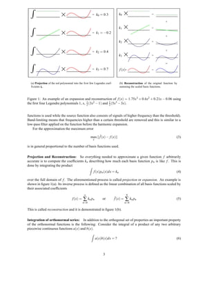
                 Figure 1: An example of an expansion and reconstruction of f (x) = 1.75x 3 + 0.6x2 + 0.21x − 0.06 using
                 the first four Legendre polynomials 1, x, 1 (3x2 − 1) and 1 (5x3 − 3x).
                                                          2               2


                 functions is used while the source function also consists of signals of higher frequency than the threshold).
                 Band-limiting means that frequencies higher than a certain threshold are removed and this is similar to a
                 low-pass filter applied on the function before the harmonic expansion.
                    For the approximation the maximum error

                                                                         max f˜(x) − f (x)                                                      (3)
                                                                              x

                 is in general proportional to the number of basis functions used.

                 Projection and Reconstruction: So everything needed to approximate a given function f arbitrarily
                 accurate is to compute the coefficients kn describing how much each basis function pn is like f . This is
                 done by integrating the product           Z
                                                                              f (x)pn (x)dx = kn                                                (4)

                 over the full domain of f . The aforementioned process is called projection or expansion. An example is
                 shown in figure 1(a). Its inverse process is defined as the linear combination of all basis functions scaled by
                 their associated coefficients
                                                                   ∞                                    N
                                                         f (x) =   ∑ kn p n           or      f˜(x) =   ∑ kn p n                                (5)
                                                                   n=0                                  n=0

                 This is called reconstruction and it is demonstrated in figure 1(b).

                 Integration of orthonormal series: In addition to the orthogonal set of properties an important property
                 of the orthonormal functions is the following: Consider the integral of a product of any two arbitrary
                 piecewise continuous functions a(x) and b(x).
                                                                          Z
                                                                                  a(x)b(x)dx = ?                                                (6)


                                                                                       3
˜
Expanding these functions into band-limited functions a and b with coefficients an and bn respectively
                                                           ˜
transforms the integral into a simple dot product of the projection coefficients.
                                           Z                    N
                                               a(x)b(x)dx = ∑ an bn .
                                               ˜ ˜                                                          (7)
                                                            i=0

This effectively reduces a symbolic integration of the product of two functions into a series of multiply-adds
which are a lot easier to compute.

Numerical Integration: When evaluating integrals for harmonic expansion (e.g. an integral of a function
that describes the incident light intensity for an given point in a complex scene), instead of performing sym-
bolic integration it is often necessary to use other solutions - especially in the field of numerical computer
simulation. One such solution is called the Monte Carlo Integration. It basically consists of taking a num-
ber of samples of the function (probabilistic gathering) and using them to approximate the correct integral
result. The more samples are taken the less error is introduced in this integration. One keyword that is used
later on when computing spherical harmonic coefficients is known as the Monte Carlo Estimator and it is
defined as
                                                       1 N
                                           Z
                                              f (x) ≈ ∑ f (xi )w(xi )                                       (8)
                                                      N i=1
where f denotes the function we want to integrate, N the number of samples, f (x i ) represents one sample and
w(xi ) represents a weighting function for each sample, which is its reciprocal probability. More information
on the topic can be found here [6, 10, 11, 13].

Examples: A prominent example that makes use of the orthogonality relationship is the Fourier series
[6], which provides a convenient method of expanding periodic functions into an infinite sum of sines and
cosines. There will be more details on the sine and cosine orthogonality later in this section since they are
one of the fundamentals spherical harmonics are built upon. Additionally a class of orthogonal polynomials
will be analyzed, named the associated Legendre polynomials. They are often interconnected with and will
be used to define as well as explore the spherical harmonics.


3.1 Associated Legendre Polynomials
The first class of orthogonal functions is named after Adrien-Marie Legendre (1752-1833), a french math-
ematician. In general represented by the symbol Plm the associated Legendre polynomials are real-valued
and defined over the range [−1, 1]. An explicit definition is

                                          (−1)m                 d l+m 2
                                  Plm =             (1 − x2)m         (x − 1)l                              (9)
                                           2l l!                dxl+m
although it is rarely used for computational purposes, because the evaluation is tricky and numerically
unstable.
    The function takes two integer arguments l and m which are constrained by l ∈ N 0 and m ∈ [0, l]. l is used
as the band index to divide the class into bands of functions resulting in a total of (l + 1)l polynomials for a
l-th band series. With respect to l and w(x) = 1 the associated Legendre polynomials obey the orthogonality
relationship
                                  Z 1
                                                                  2(l + m)!
                                       Plm (x)Plm (x)dx = δll                  .                            (10)
                                    −1                        (2l + 1)(l − m)!
However, for different m on the same band, the polynomials are orthogonal with respect to a different
constant and another weighting function. If neither m = m nor l = l the polynomials are not orthogonal
at all. When used in spherical harmonics, this orthogonality needs to be established by another orthogonal
polynomial.
    For a better understanding the first few functions are shown in figure 3.1 and used for the harmonic
expansion in figures 1(a), 1(b) with l = 0..3 and m = 0. If m = 0, as it can be found in the aforementioned


                                                        4
l    m Pm (x)
                l
                                                                                                        2
                                                                                                       P3 (x)
        0    0      1
                                                                                                         2
                                                                                                        P2 (x)
         1 0        x
                 √                                                               1
         1    1 − 1 − x2                                                        P3 (x)
                                                                                                         0
                                                                                                        P0 (x)
                    1    2                                                               1
        2    0      2 (3x − 1)
                                                               0
                                                              P3 (x)                           0
                                                                                              P1 (x)
                   √                                           −0.5                                         0.5

        2     1 −3x 1 − x2
                                                                                          0
                                                                                         P2 (x)
        2    2      3(1 − x2 )                                          1
                                                                       P1 (x)
                                                                                         −1

                                                                                                             1
                                                                                                            P2 (x)
                    1    3
        3    0      2 (5x − 3x)
                    3
                                √
        3     1     2 (1 − 5x2 ) 1 − x2                                                                               3
                                                                                                                     P3 (x)

        3    2      15x(1 − x2 )
        3    3      −15 (1 − x2 )3

                 Figure 2: First four bands l = 0, ..., 3 of the associated Legendre polynomials


example, they degenerate to the unassociated Legendre polynomials, which will however not be discussed
in this work.
    The associated Legendre polynomials can also be defined using a set of recurrence relations
                                   m
                                 Pm (x)     = (−1)m (2m − 1)!!(1 − x2)m/2                                                     (11)
                                m                       m
                               Pm+1 (x)     = x(2m + 1)Pm (x)                                                                 (12)
                          (l − m)Plm (x)                m                    m
                                            = x(2l − 1)Pl−1(x) − (l + m − 1)Pl−2(x)                                           (13)

which will come in handy when implementing the function in a computer application, especially since
they are easier to compute and less susceptible to numerical errors compared to other methods [6, 14]. To
evaluate a given function value Plm (x) primarily equation (11) is used to generate the highest Pm possible.
                                                                                                     m

Thereafter for l = m the correct value has been computed. Otherwise all that is left to do is to raise the band,
so (12) is used once to get to the next band, and then (13) can be iterated (because it depends on l − 1 and
l − 2 results the second rule needs to be applied once) until the correct answer is found.


3.2 Sine and Cosine
The other important set of orthogonal functions is the sine and cosine set. Despite being the key func-
tions when talking of spherical or circular systems, they also obey the orthogonality relation over [−π, π].
Following key integral identities can be defined, and will be of good use when defining spherical harmonics:
                                               Z π
                                                     sin(mx) sin(nx)dx = πδmn                                                 (14)
                                                −π
                                              Z π
                                                     cos(mx) cos(nx)dx = πδmn
                                                −π
                                               Z π
                                                     sin(mx) cos(nx)dx = 0
                                                −π
                                   Z π                  Z π
                                          sin(mx)dx =         cos(mx)dx = 0
                                     −π                  −π

whereas m, n = 0 are called phases. As noted above, these integral identities are one of the key properties
the Fourier Series is built upon.


                                                          5
Another important property of the sine and cosine functions is related to the complex numbers. It is
called the Euler identity and defined as

                                            eiφ = cos(φ) + i sin(φ).                                       (15)

   For more information, see [6, 5].


4 Spherical functions
Now the key fundamentals for the main topic are defined and explained. But before this work jumps into
the colorful world of spherical harmonics, there are some small conventions that need to be reviewed in
order to ensure a proper understanding.

4.1 Spherical polar coordinates

    When talking about spherical functions it is convenient to use spherical polar                    z
coordinates instead of the Cartesian ones. The spherical coordinate system is
                                                                       PSfrag replacements
defined by two angles θ and φ, whereas 0 ≤ φ < 2π describes the azimuthal angle                       θ r
in the xy-plane originating at the x-axis and 0 ≤ θ < π denotes the polar angle                              y
                                                                                                    φ
from the z-axis. Additionally a radius r is used to represent the distance from the               x
origin of the coordinate system, but it can be omitted for normalized coordinates,
which all lie on a unit sphere and therefore have a uniform distance from the
origin of r = 1. See figure 3. Care has to be taken when comparing spherical
                                                                                         Figure 3: Polar coordi-
functions from different sources, since there is no generally accepted convention
                                                                                         nate system
about the semantics of φ and θ, thus they may be swapped or defined differently.
    The relations between a point in the Cartesian and spherical polar coordinate systems for this work are
defined as

                                  r   =  x2 + y2 + z2                                                      (16)
                                            y
                                  φ = cot                                                                  (17)
                                            x
                                                 x2 + y2                  z
                                  θ = sin−1                     = cos−1                                    (18)
                                                   r                      r

and analogously the inverse relations

                                              x = r cos φ sin θ                                            (19)
                                              y = r sin φ sin θ                                            (20)
                                              z = r cos θ.                                                 (21)

4.2 Definition
A spherical function is a mapping of spherical coordinates (θ, φ) to a scalar value. In this work spherical
functions are assumed to be real-valued, although complex-valued functions can be harmonically expanded
by the complex spherical harmonics series analogously. Spherical functions can easily be visualized by
either displaying a textured sphere, where the intensity of a point on the surface represents the value of
the function at that point (Figure 4(b)), or by displacing the points on the surface of the sphere along their
corresponding normal vector based on the value of the function (Figure 4(a)).
    An integration can be thought of as summing infinitesimal patches of area. The parameterization of a
sphere using polar coordinates causes the patches on the equator to be bigger and thus should have more
influence on the solution of the integral compared to the patches at the poles. To encode this effect an
integration of a spherical function is pre-multiplied by sin(θ) which is 1 at the equator, vanishes at the poles
and is directly proportional to the area of the patches (which only depends on θ). To enhance readability,


                                                       6
(a) Displaced unit sphere with random coloriza-        (b) Textured unit sphere, using the spectrum shown on
          tion.                                                  the right side to visualize high and low function values.


Figure 4: An exemplary spherical function f (θ, φ) = 1 (cos(6φ)3 + sin(θ)4 + 1) plotted with both presented
                                                     4
techniques.


such an integration of a spherical function f (θ, φ) over the surface of a unit sphere S will be expressed either
in the explicit spherical coordinate form or as an integral over the implicit surface S.
                                       Z 2π Z π                               Z
                                                      f (θ, φ) sin(θ)dθdφ =           f (ω)dω                                (22)
                                           0      0                               S

   Analogously, an integral over the surface of an hemisphere Ω(n) in direction n is denoted as
                                Z 2π Z π                                              Z
                                               f (θ, φ) sin(θ)h(n, θ, φ)dθdφ =                   f (ω)dω                     (23)
                                 0     0                                                  Ω(n)

whereas
                                                                 1 0 ≤ n · vθφ
                                                  h(n, θ, φ) =
                                                                 0 otherwise
with vθφ being the vector from the center of the unit-sphere to the point described by θ and φ. Additionally
later on xω will be used to describe any point in direction ω.


5 Spherical Harmonics
Now we finally arrived at the actual topic of this work and the spherical harmonics are very close. With all
the required fundamentals defined now a formal write up and explanation of the definition of the spherical
harmonics will follow. After that details of the important properties that result from this definition will be
discussed. Finally rotation of a spherical harmonic function are described briefly.

5.1 Definition
In section 3 it is shown that the associated Legendre polynomials can be used to express any piecewise
continuous function over the interval [−1, 1] either as an infinite series of polynomials, a finite series of
polynomials for a band-limited approximation or a finite series of polynomials in case the function itself
does not have frequencies higher than a certain threshold. When looking at the definition of spherical


                                                                 7
coordinates in section 4 it may become obvious that we can express any circularly symmetric function (like
                 l = 2, m = 0 in figure 6), which has no dependence on φ, in terms of the associated Legendre polynomial
                 by mapping θ into the [−1, 1] domain using cos θ. But we need some mechanism to provide orthogonality
                 in case of non-circular symmetric functions. This can be realized by combining the associated Legendre
                 polynomials for the θ dependence with the sine and cosine functions for the φ dependent part. Now with
                 the basic idea explained a formal description of the spherical harmonics will follow and finally they will be
                 investigated.


                 A complete formal definition of the complex-valued spherical harmonic series with two arguments l ∈
                 N0 and −l ≤ m ≤ l is given by

                                                                            |m| |m|
                                                         Ylm (θ, φ) = Nl Pl (cos θ)eimφ                                 (24)

                 where Nlm is a normalization coefficient. As for the Legendre polynomials l denotes the band index. Using
                 Euler’s formula the equation can be rewritten as

                                                              |m| |m|
                                              Ylm (θ, φ) = Nl Pl (cos θ)(cos(mφ) + i sin(mφ))                           (25)

                 and it becomes evident that, as described above, the spherical harmonics are based on the associated Leg-
                 endre polynomials for the θ and sine and cosine functions for the φ dependence. See figure 5.


                                                   X                                                =


PSfrag replacements
                                                                                                        y2 (θ, φ)
                                                                                                         4

                               sin(2φ)                                      2 (7 cos θ − 1) sin θ
                                                              2            25       2          2
                                                             P4 (cosθ) =


                 Figure 5: A demonstration of the functional dependencies of both coordinate axes. The left image shows
                 the φ dependence with the corresponding sine-wave (phase m = 2) while the center image displays the θ
                                                                            2
                 dependence along with its associated Legendre polynomial P4 . Combining both yields the right picture of
                                                        2.
                 the spherical harmonic basis function y4


                      The normalization factor can then be derived from
                                                    Z
                                                         Ylm (ω)Ylm (ω) sin(θ)dω = δmm δll                              (26)
                                                     S


                 which concurrently proofs the orthogonality of the spherical harmonics. The sin(θ) weights the function
                 values by the distance from the equator. This is due to the aforementioned fact that integrating spherical
                 coordinates can be seen as integrating small patches on the sphere.


                                                                              8
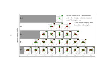
This figure illustrates the first 5 spherical harmonic

                                            l=0                                     bands l = 0...4. Green parts indicate positive extends
                                                                                    while red shows negative ones.

                                                                                                    The little sphere on the top right shows
                                                                                                    the distribution on the unit sphere.
                                            l=1
             Figure 6: SH basis functions


                                            l=2
9


                                            l=3

PSfrag replacements

                                            l=4


                                                  m=−4   m=−3   m=−2   m=−1   m=0   m=1              m=2             m=3              m=4
Solving the equation (26) by expanding Ylm yields:
                                 Z 2π Z π
                                                  Ylm (θ, φ)Ylm (θ, φ)sin(θ)dθdφ
                                     0        0
                                 Z 2π Z 1
                             =                     Ylm (θ, φ)Ylm (θ, φ)d(cos θ)dφ
                                     0       −1
                                 Z       2π Z 1
                                                     |m|    |m | |m|       |m |
                             =                     Nl Nl        Pl (cos θ)Pl (cos θ)eimφ eim φ d(cos θ)dφ
                                     0        −1
                                                   Z 1                                             Z 2π
                               |m| |m |                     |m|          |m |
                             =Nl Nl                        Pl (cos θ)Pl         (cos θ)d(cos θ)           eimφ eim φ dφ                 (27)
                                                    −1                                              0
                                                                   θ-dependent part                 φ-dependent part

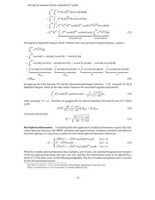
Solving the φ dependent integral, which is based on the sine and cosine integral identities, results in
      Z 2π
             eimφ eim φ dφ
       0
      Z 2π
  =          (cos(mφ) + i sin(mφ))(cos(m φ) − i sin(m φ))dφ
       0
      Z 2π
  =          cos(mφ) cos(m φ) + sin(mφ) sin(m φ) + i cos(m φ) sin(mφ) − i cos(mφ) sin(m φ)dφ
      Z0                                    Z                                     Z                                Z
  =        cos(mφ) cos(m φ)dφ +                   sin(mφ) sin(m φ)dφ +i(              cos(m φ) sin(mφ)dφ −             cos(mφ) sin(m φ)dφ)

                   =πδmm                                   =πδmm                              =0                             =0

  =2πδmm                                                                                                                                (28)

by applying the Euler formula (15) and the aforementioned integral identities 1 (14). Similarly for the θ
dependent integral, which on the other hand is based on the associated Legendre polynomials:
                                     Z 1
                                                                                            2 (l + m)!
                                              Plm (cos θ)Plm (cos θ)d(cos θ) =                          δ                               (29)
                                         −1                                              2l + 1 (l − m)! ll

while assuming 2 m = m . Therefore, by plugging the two derived identities (28) and (29) into (27), which
yields
                                        4π (l + m)!
                              Nlm Nlm                δ δ    = δll δmm ,                              (30)
                                      2l + 1 (l − m)! ll mm
it becomes obvious that
                                                                          2l + 1 (l − m)!
                                                              Nlm =                       .                                             (31)
                                                                            4π (l + m)!

Real Spherical Harmonics: Considering that most applications of spherical harmonics require only real-
valued spherical functions, like BRDF calculation and approximation, irradiance estimation and spherical
harmonic lighting, it is convenient to define the real-valued spherical harmonics function as
                              √                √
                               2ℜ(Ylm ) = 2Nlm cos(mφ)Plm (cos θ)
                                                                          if m > 0
                          m
                         yl =   Yl0 = Nl0 Pl0 (cos θ)                      if m = 0                (32)
                              √                √ |m|           |m|
                                   2ℑ(Yl ) = 2Nl sin(|m|φ)Pl (cos θ) if m < 0
                                       m


While the complex spherical harmonic basis includes a pair of sines, the separated imaginary and real parts
of the real spherical harmonics only have one sine, and thus the normalization needs to be adjusted by a
          √
factor of 2 for those cases. In the following paragraphs, only the real spherical harmonic part is covered,
for the aforementioned reasons.
  1 Note
               R π            R  π+a
           that −π sin(x)dx = −π+a sin(x)dx because of the periodical appearance of sine and cosine.
  2 There   is no need for the m = m case because it is already handled by (28)


                                                                            10
Instead of using two parameters it is sometimes useful to flatten the spherical harmonic functions in
a specific order into a one dimensional vector, so that they can easily be enumerated. Thus the function
yi (θ, φ) = ym (θ, φ) with i = (l + 1)l + m is used whenever suited.
             l
     To get a better understanding of the spherical harmonics and what they look like, the first few functions
can be seen in figure 6.
     All three classes of spherical harmonics are illustrated:

    • The zonal harmonics are all spherical harmonics with m = 0 which means that they are circular
      symmetric as described in the example at the beginning of this section. They are termed zonal since
      the visual curves that appear on the unit sphere are parallels of the equator (latitude) and they divide
      the unit sphere into zones. It may also be relevant to mention that since m = 0 the harmonics reduce
      to associated Legendre polynomials.
                                                                     m
    • Sectoral harmonics are those spherical harmonics of the form Y|m| .

    • Tesseral harmonics are all other spherical harmonics. The related unit sphere is usually divided into
      several blocks in longitude and latitude.

5.2 Properties
The following section will cover the most important properties of the spherical harmonics.

5.2.1 Harmonic expansion
Since it has already been illustrated that spherical harmonics form an orthonormal basis, projecting a spher-
ical function into spherical harmonic coefficients is simple and a straight forward application of definition
(4). Replacing the arbitrary polynomial basis pn by the real spherical harmonic basis function yi transforms
the equation into                                  Z
                                             ki =       f (s)yi (s)ds.                                      (33)
                                                    S


Source function    n=0           n=2          n=4               n=6       n=8          n=10          n=15


Source function    n=0           n=4          n=6               n=10      n=15         n=20          n=25


        Figure 7: An example of a band-limited spherical harmonic expansions. n denotes the order.


    By combining this with the aforementioned Monte Carlo estimator a numerical solution for the coef-
ficients ki can be defined. In the Monte Carlo estimator a weighting function is used for every sample. If
the samples are carefully chosen, by making them independent of the parameterization of the sphere using
a technique like stratified sampling as described by [12], the weighting function turns into a constant term
                                                                    1
because all samples have an equal probability. This probability is 4π for an equal distribution of samples


                                                        11
on the surface of a unit sphere and therefore the resulting weighting function is w(x i ) = 4π. The numerical
solution for the integration problem can then be rewritten as
                                           n                              n
                                      1                             4π
                               ki =
                                      n   ∑ f (x j )yi (x j )4π =    n   ∑ f (x j )yi (x j )              (34)
                                          j=1                            j=1

with n → ∞. Some examples for such expansions can be seen in figure 7.
    What can also be seen in the figure is that using a finite series of coefficients will only reconstruct an
approximation of the original function except the source function does not have higher frequencies than
the ones that can be captured by the highest order spherical harmonic band used. (n + 1) 2 coefficients are
used for such a band-limited approximation of the n-th order. This quadratic growth makes it crucial to find
the right trade-off between quality of the approximation and memory consumed by the coefficients. Ra-
mamoorthi and Hanrahan [3] as well as Basri [4] have shown that for lambertian reflectance and irradiance
approximation a second order approximation (using a 9 coefficients, a 9D subspace as they call it) is already
sufficient. More details about this will follow later when providing some examples of spherical harmonics
in computer graphics.

5.2.2 Convolution
Imagine a convolution of a spherical function f with a kernel function k. For example it can be a low-
pass filter in order to remove high frequencies from the spherical function, maybe to prevent artifacts when
computing a band-limited expansion of a high frequency function. This kernel function has to be circular
symmetric, which implies that it does not have any φ dependence, because the result of a non-symmetric
convolution would not be defined over the sphere, but rather in the corresponding special orthogonal group
SO3 . Applying the Funk-Hecke-Theorem [4] yields

                                                         4π 0 m
                                      (k f )m =
                                            l                k f = αl kl0 flm                             (35)
                                                       2l + 1 l l
which means that harmonic expansion of the convolution is equal to expanding both functions separately,
scaling them by αl . Therefore the spherical harmonic reconstruction of a convolution can be written as
                                                       ∞     l
                                          f˙ = k f = ∑      ∑    (αl kl0 flm )Ylm .                       (36)
                                                      l=0 m=−l


5.2.3 Rotational invariance
Let g be a copy of f rotated by an arbitrary rotation R over the unit sphere. The following relationship can
be defined:
                                               g(s) = f (R(s))                                          (37)
In other words it does not matter if the function or the input is rotated - the result is the same. This
is a very critical property called rotational invariance (readers familiar with the one-dimensional Fourier
transformation may see the analogy to the shift-invariance property).
    In practice this means that no aliasing artifacts will occur when samples from f are collected at a rotated
set of sample points. A more specific example would be that rotating a light function will not cause any
light amplitude fluctuation.

5.2.4 Fast Integration
The fast integration of the product of any two spherical functions a and b has already been explained in the
section about orthonormal polynomials. But to underline the importance of this property consider having
some sort of light transfer function that transforms any given incident light into a certain amount of exiting
radiance. If both the incident light function and the transfer function are expressed in terms of spherical
harmonics, the evaluation of the exiting radiance can be reduced to a dot product of the coefficients. This can
even be quickly calculated in a fragment or vertex shader on the newer generations of graphics hardware at


                                                           12
an incredible fast rate, while the evaluation of an arbitrary integral over the upper hemisphere in the shader
would just not work at all. The Spherical Harmonic Lighting technique (section 6.2) will make good use of
this property.

5.2.5 Transfer Matrix
Now consider expanding the multiplication of two spherical functions c(ω) = a(ω)b(ω) into spherical
harmonic coefficients, whereas a(ω) can be evaluated at projection time, while it is not possible for b(ω).
Think of b(ω) as a visibility (or maybe lighting) function and a(ω) as some kind of weighting function,
representing occluders that limit the visibility function (or the lighting) or maybe even extend it when the
function value is ≥ 1 - which is a bit hard to imagine though, but could possibly be explained by some kind
of optical magnification effect (binoculars). Sloan et al. [16] described this as a linear transformation of
b j ’s coefficients by a matrix a which can be obtained by factoring out b in the spherical harmonic expansion
                               ˆ
of c:
                                       Z                                   Z
                                ci =        c(ω)yi (ω)dω =                         a(ω)b(s)yi (ω)dω
                                       ZS                                      S

                                  =         ∑(ak yk (ω)) ∑(b j y j (ω))yi (ω)dω
                                           S k                        j
                                             Z
                                  = ∑(            ∑(ak yk (ω))y j (ω)yi (ω)dω)b j
                                        j        S k
                                                       Z
                                  = ∑ ∑(ak                     yk (ω)y j (ω)yi (ω)dω)b j
                                        j    k             S

                                  = ∑ ai j b j
                                      ˆ                                                                  (38)
                                        j

and thus                                                       Z
                                       ai j = ∑ ak
                                       ˆ                            yk (ω)y j (ω)yi (ω)dω.               (39)
                                                  k             S

    In other words transforming any given vector of spherical harmonic coefficients b by the transfer matrix
will yield a new vector of coefficients c, which is equal to the harmonic expansion of a(ω)b(ω). The
described matrix is mostly sparse and symmetric which provides room for programmatic optimizations.
    What this technique makes possible is to integrate over a triple product of functions, with two distinct
unknown parameters (while using the aforementioned fast integration only allows the dependence on one
unknown parameter). An exemplary usage of this transfer matrix can be found in Sloan, Snyder and Kautz’s
paper [16]. They are using it to model glossy radiance transfer, whereas both the view-dependent reflection
direction (BRDF) and the incident light function (incident radiance) are unknown at pre-computation time.


5.3 Rotation
It has already been explained that when rotating a spherical harmonic expanded function its extents will be
sustained exactly. But calculating such a rotation is not as easy as rotating an ordinary vector space. Robin
Green [12] has described this problem in depth and even called it a royal pain-in-the-ass when using a naïve
approach. I will only cover a small presentation of the problem and the solution that has been proposed by
Kautz et al. [17]. As we will see this only works well for the first couple of spherical harmonic bands, but
that is enough for the cause of this work. The interested reader can find more information on the problem
in various sources [18, 19, 20, 21]. Here is how a low-order rotation may be computed:
    From the orthogonality property it can be derived that when transforming coefficients of a particular
band in the resulting function only coefficients of that same band are affected. What does this mean?
Firstly it means that a rotation can be expressed as a linear transformation, a n × n matrix to be exact.
Secondly this matrix will be block diagonal sparse, which means that it will contain several "transformation
blocks" on the principal diagonal each spanning the rectangular region of a transformation of a single band.
So the key to a rotation would be to find a efficient set of recurrence relations that depending on the n-th


                                                                      13
band rotation returns the n + 1-th band matrix. Such relations can be found in the aforementioned papers
but will not be described here.
    Let us get back to the matrix. Each entry in the matrix Mi j describes how much a source coefficient
j is like the rotated coefficient i. Recalling the method to determine how much a orthogonal basis is like
another this can be formulated as                Z
                                               Mi j =            ˆ
                                                             yi (Rω)y j (ω)dω                              (40)
                                                         S

whereas R denotes the rotation. For example, an arbitrary rotation about the z-axis (= φ) by α is
        ˆ
                                                     Z
                                        Mizj (α) =           yi (θ, φ + α)y j (ω)dω.                       (41)
                                                         S


     The rotated coefficients c j can be computed from the source coefficients c j using the linear transforma-
tion c j = ∑i Mi j c j .
     But this method computed for an arbitrary angle can quickly become very expensive. Instead the trick
is to convert the rotation matrix into its ZYZ-Euler angle decomposition. A ZYZ-Euler rotation works by
first rotating around the z-axis, then the y-axis and finally the z-axis again. Computing the z-axis rotation is
easy [12], but the y-axis is more complex. However the y-axis rotation can be decomposed: Firstly, rotate
about the x-axis by 90o and secondly do a general rotation about the z-axis. Finally rotate back about the
x-axis by −90o. The two x-axis matrices are transposed counterparts and can be pre-calculated, since they
are fixed. This can even be optimized further as described by Robin Green [12] but since this work is not
about implementational specifics those optimizations are not covered here.


6 Spherical Harmonics in Computer Graphics
In the following section I will give some examples of what spherical harmonics can be used for in the
fields of computer graphics. The examples focus on enhancing real-time rendering by sourcing out or
approximating parts of the lighting equation using spherical harmonics. Usage of spherical harmonics is
not limited to these applications though, since they can also be utilized for object recognition and image
based relighting [3, 4].


6.1 Irradiance Environment Maps
The first technique has been developed by Ravi Ramamoorthi and Pat Hanrahan at the Stanford University.
They propose an efficient representation for irradiance environment maps using spherical harmonics [3].


Environment maps: An environment map is used to store distant lighting distribution denoted by L.
Since it is assumed to be very far away, there is no noticeable variance in the lighting on an object, all
points on the surface are lit equally. Based on the normal vector n the incident light at an arbitrary point can
be looked up. Such a lookup represents the result of an integration over the upper hemisphere Ω(n) at that
point, while not taking into account near illumination or visibility information (e.g. no shadows). The light
model is assumed to be lambertian and thus such an integral can be described as the convolution
                                   Z
                                              L(ω)(n · ω)dω = L A(n) = E(n)                                (42)
                                       Ω(n)


whereas E(n) represents the irradiance of the surface and describes the grand total of incident light. So an
environment map represents a way to map a normal n to its corresponding irradiance E(n) (which multiplied
by the surface albedo corresponds to the image intensity). It is possible to pre-compute this convolution for
every normal direction, since the environment map is static. Such a pre-computation is called pre-filtering
and the result is a very blurry environment map.


                                                                14
Figure 8: Image courtesy of Ramamoorthi and Hanrahan. It shows the result of their Efficient Representa-
tion of Irradiance Environment Maps [3] rendered in real-time.


The new approach: What Ramamoorthi et al. noticed is that this convolution can be expressed in terms
of spherical harmonics and solved very efficiently in frequency space. Expanding the light function L in
terms of spherical harmonics yields
                                       L(θ, φ) = ∑ LmYlm (θ, φ)
                                                      l                                            (43)
and defining max(n · ω, 0) = max(cos θ, 0) as the circular symmetric kernel function, also in its spherical
harmonic expansion with m = 0,

                                       A(n) = max(cos θ, 0) = ∑ Al Yl0 (n)                              (44)

it turns out (36) that the convolution (42) can be written as

                                             E(n) = ∑ αl Al LmYlm (n).
                                                             l                                          (45)

Very intriguing about this solution is that because αl vanishes very fast the irradiance is well approximated
by only 9 coefficients. The maximum error for any pixel is 9% [3].
   Especially for rendering this is a very important property since when writing down the first 9 spherical
harmonics in Cartesian coordinates

                                    Y00 (x, y, z) =                              0.282095
                         −1
                      {Y1 ;Y10 ;Y1 }(x, y, z)
                                   1
                                                   =                      0.488603{x; z; y}
                                   Y20 (x, y, z)   =                     0.315392(3z2 − 1)
                                   Y22 (x, y, z)   =                     0.546274(x2 − y2)
                     {Y2−2 ;Y2−1 ;Y2 }(x, y, z)
                                   1
                                                   =                 1.092548{xz; yz; xy}               (46)


                                                        15
Grace Cathedral Lightprobe


                                                        Eucalyptus Grove Lightprobe

Figure 9: Image courtesy of Ramamoorthi and Hanrahan. It shows a source environment map and its
pre-filtered counterparts using the standard image-space method (left) and the spherical harmonic approach
(right).


it becomes evident that this computation can easily be performed on the fly on modern fragment or vertex
shader hardware by solving the quadratic polynomial (45).

                      2   l
         E(x, y, z) = ∑   ∑     αl Al LmYlm (x, y, z)
                                       l
                     l=0 m=−l

                  =c1 L2 (x2 − y2 ) + c3L0 z2 − c5 L0 + c4 L0 + 2c1 (L−2 xy + L1 xz + L−1 yz)
                       2                 2          2       0         2        2       2                   (47)
                     + 2c2(L1 x + L−1y + L0 z)
                            1      1      1
               c1 =0.429043 c2 = 0.511664 c3 = 0.743125 c4 = 0.886227 c5 = 0.247708

Alternatively the spherical harmonic coefficients for every point on the surface can be precomputed once,
which reduces the real-time calculation to only a scalar product of the vertex normal’s coefficients and the
irradiance coefficients. It should be denoted that each color channel needs a separate set of coefficients
because the lighting function only represents amplitude of light, no colorization. For rendering, the result
of the aforementioned equation need only to be multiplied by the surface albedo, which is usually taken
from texture map, to yield the final pixel output.


Pre-filtering results: Traditionally an environment map is represented by either a cube map (which is
constructed using six two-dimensional textures representing the sides of a cube) or a two dimensional
texture - using a special coordinate mapping, called sphere mapping, to warp the 2D image onto the surface
of a sphere. Figure 9 shows such a two-dimensional mapping of two light-probes [15]. As asserted before
the quality does not differ much. The images on the right side represent the pre-filtered irradiance maps.
With a traditional approach pre-filtering takes O(S · T ) time, where S is the size of the source texture (light-
probe in this case) and T the size of the resulting irradiance texture (usually something around 64x64=4096
texels or even larger). The new approach by Ramamoorthi et al. only needs O(9 · T ), because only 9
coefficients need to be computed. It is obvious that while saving a lot of processing time this also saves a
lot of memory.


                                                            16
6.2 Spherical Harmonic Lighting
6.2.1 Introduction
This may be the most impressive example for the usage of spherical harmonics in computer graphics.
Spherical harmonic lighting is a technique that can effectively deliver real-time dynamic global illumination
at a very high performance. There are some limitations, but most of them can be circumvented.

The Rendering Equation: Before starting with the spherical harmonic solution of the lighting equation,
one of the holy grails of real-time computer graphics will be introduced: the accurate computation of what
Kajiya has referred to as the rendering equation [22] - completely in real-time. The rendering equation
expresses the light intensity transferred from a point x in direction ω v and in differential angle form it is
defined as                                   Z
                   L(x, ωv ) = Le (x, ωv ) + R(x, −ω, ωv )L(xω , −ω)G(x, xω )V (x, xω )dω.               (48)
                                             S

Le (x, ωv ) describes the light that is emitted by the point x in direction ωv independent of any incident
light (e.g. an emissive surface like phosphor). Modeling this is the easiest part. R(x, ω, ω v ) is the scalar-
valued bi-directional reflectance distribution function (BRDF) and it scales the light reflected at point x
into direction ωv depending on the incident direction ω. The geometric relationship G(x, x ) describes how
the two parameter points x and x are related to each other whereas x is some other point of the scene in
direction ω from x. One of the most prominent examples for such a relationship is the lambertian cosine
term. Finally V (x, x ) describes the visibility relationship between the two points, which is either 1 or 0. It
becomes true if a ray cast from x to x is not occluded by any other geometry and is false otherwise. The
most difficult problem of this equation is to solve the recursion of L(x, ω v ) also termed interreflection.

Review of previous solutions: Here is a quick review of previous real-time solutions for this equation:
    Id Software’s Quake (1996) pioneered with a solution called real-time light-mapping. This technique
uses a radiosity algorithm [24] to pre-compute the diffuse lighting (which was very time consuming and
took hours to days) of the entire scene, storing it into textures. One implication of this approach was that
no dynamic lighting could be taken into account when computing the lightmaps. Additionally the BRDF
had to be static since the lambertian reflection model uses an equal distribution of light into all directions
(R(x, ω, ωv ) is constant). Dynamic lighting was faked by additive blending of unshadowed diffuse point
light sources with V (x, x ) = 1 and no interreflections.
    This technique can still be found in a lot of modern games, with the most prominent example being
Half-Life 2 by Valve Software. They are using a modified version of this technique where the lightmap
is computed from three different angles. Thereby they circumvent the BRDF limitation and are able to
approximate glossy reflections [23].
    A more modern approach is to use stencil volume shadows or shadowmaps to solve the equation. While
this technique allows completely dynamic lighting, there are no interreflections. Additionally point lights
are assumed. Since those have no area and only consist of one point - hard shadow edges are implied.
There are workarounds that simulate spherical area lights using points lights followed by a smoothing of
the shadow edge.
    So in the past you always had to choose between quality (in terms of interreflection and area lights)
and flexibility (dynamic light sources). Using spherical harmonics it is possible to have both - real-time
dynamic lightsources with interreflections and area light sources. Although there are limitations it still is a
step towards the goal.

6.2.2 The new algorithm
Now the solution developed by Sloan et al. [16] be described in detail (a programmatic explanation has
been written by Robin Green [12]). The basic idea is to divide the rendering equation into a light source
function LI as well as a (pre-computable) transfer function T :
                                                        Z
                            L(x, ωv ) = Le (x, ωv ) +       LI (x, −ω)T (x, −ω, ωv )dω                     (49)
                                                        S


                                                            17
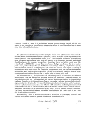
Figure 10: Example of a scene lit by pre-computed spherical harmonic lighting. There is only one light
source, the sun, but notice the interreflections that cause the ceiling, the top of the pedestal and the wings
of the statue to be slightly illuminated.


     The light source function LI (x, ω) describes exactly the fraction of the light incident at point x from di-
rection ω that has been emitted directly from a lightsource - without taking into account any interreflections
(indirect lighting). There are two possible settings for LI . Firstly, given the ideal setting of low variation
of the light source function for the entire scene only one copy of the light source function is required and
shared by all points. For instance a setting where a distant light like the sun lighting a small scene (like
a chessboard) would fulfill this property. This works because the light is so far away that given any two
points x and xω on the surface of the scene the difference between LI (x) and LI (xω ) is neglectible. Secondly,
if the environment consists of local lighting (eg. light sources that are close to the object) L I will vary at
different points on the object. In this case it is possible to take samples of the light function and interpolate
between them when rendering, effectively creating a field of incident lighting. This does, however, break
some assumptions about interreflections that we need to make, so this can not be used
    The transfer function T (x, ω, ωv ) describes how light arriving from LI is transformed into irradiance
in direction ωv . Note that not only light arriving at the point x is transformed. Since there possibly are
interreflections arriving at x, T might transform light that does not directly arrive from the lightsource into
irradiance. Depending on the light model used, T can be expressed as a spherical function which optionally
depends on the view-direction. For view-dependent light models the transfer functions need to be approxi-
mated by a spherical harmonic transfer matrix (Chapter 5.2.5) to transform incident light into a new set of
coefficients that can later be convolved with the BRDF. On the other hand the transfer functions for view-
independent light models can be approximated by only using a vector of spherical harmonic coefficients.
The transfer functions for both cases are generated in a pre-computing step - that is likely to take a long
time for a detailed approximation.
   When rendering a point on the surface its intensity is the solution of equation (49). But since both
functions are expressed in terms of spherical harmonics the equation reduces to

                                        L(x, ωv ) = Le (x, ωv ) + ∑ LI Ti
                                                                     i                                      (50)
                                                                  i


                                                       18
for diffuse and
                               L(x, ωv ) = Le (x, ωv ) + ∑ αi Ri (∑ Ti j LIj )yi (ωv )                    (51)
                                                                    i        j

for view-dependent light models whereas ∑ j Ti j LIj is the linear transformation of the light coefficients by
the transfer function and the sum over i describes the convolution of the BRDF kernel R with the transfered
light function. Evaluating ym returns the value of the convolved function at ωv (which is the view-direction).
                            l
    From now on the lambertian reflection model will be assumed and therefore no glossy reflections will
be described, although an in depth discussion of this reflection type can be found in [16].

6.2.3 Transfer functions
After this rather quick and dirty overview it is time to go into more detail about the transfer function. Since
in the lambertian model light is reflected equally in all directions, the aforementioned rendering equation
can be simplified by removing all view-dependent parts:
                                                 ρ(x)
                                                         Z
                          Llam (x) = Le (x) +                     L(xω , −ω)G(x, xω )V (x, xω )dω         (52)
                                                  π           S

The BRDF in this case reduces to constant term ρ(x) which is called the surface albedo at point x. It
describes the ratio of radiosity (which corresponds to image intensity) versus irradiance. Now all that
remains in the equation is the amount of incident light L, the geometric relationship, and the visibility
functions.
    Recalling the geometric relationship in a diffuse environment being defined as the non-negative max(n x ·
v, 0) (has already been used in the section on environment maps), whereas n x is the normal vector at the
point x and v the direction of the incident light, the equation can be expanded to
                                          ρ(x)
                                                 Z
                    Llam (x) = Le (x) +                     L(xω , −ω) max(nx · vω , 0)V (x, xω )dω.      (53)
                                           π     Ω(nx )

The integral domain reduces to the upper hemisphere since for the lower hemisphere the cosine term would
be 0.
    Three different types of transfer functions can be derived from this equation. Each one adds more detail
to the lighting, but also takes more time to compute. I will only give a brief idea on how the following
transfer functions can be evaluated using ray-casting, for details consult Green’s paper [12].

Diffuse Unshadowed Transfer Function: The first transfer function T DU does not take into account the
visibility term V (x, x ) or interreflections. Therefore the rendering equation reduces to
                                              ρ(x)
                                                        Z
                         LDU (x) = Le (x) +                         LI (x, −ω) max(nx · vω , 0)dω.        (54)
                                               π          Ω(nx )

Comparing (54) to (49) it quickly becomes clear that the transfer function has to be
                                          T DU (x, ω) = max(nx · vω , 0).                                 (55)
    The result of a scene lighted with this function looks very similar to normal dot-product lighting, except
that instead of point or directional light sources any area light source can be used. Example usage of diffuse
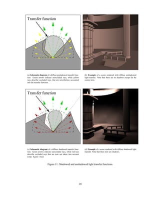
unshadowed transfer functions can be found in figures 11(a) and 11(b).

Diffuse Shadowed Transfer Function: The second transfer function T DS is very similar to the afore-
mentioned one. In addition to T DU it does, however, include the visibility term. Therefore,
                                          ρ(x)
                                                 Z
                     LDS (x) = Le (x) +                       LI (x, −ω) max(nx · vω , 0)V (x, ω)dω.      (56)
                                           π         Ω(nx )

whereas V (x, ω) is true as soon as the ray with origin at x in direction ω is intersecting parts of the scene,
opposed to V (x, x ) where the ray check is only performed in between x and x . Following (49) yields
                                    T DS (x, ω) = max(nx · vω , 0)V (x, xω ).                             (57)


                                                                  19
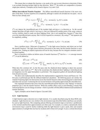
Transfer function


(a) Schematic diagram of a diffuse unshadowed transfer func-        (b) Example of a scene rendered with diffuse unshadowed
tion. Green arrows indicate unoccluded rays, while yellow           light transfer. Note that there are no shadows except for the
rays describe occluded rays, that are nevertheless accounted        cosine term.
into the transfer function.


Transfer function


(c) Schematic diagram of a diffuse shadowed transfer func-          (d) Example of a scene rendered with diffuse shadowed light
tion. Green arrows indicate unoccluded rays, while red rays         transfer. Note that there now are shadows.
describe occluded rays that are now not taken into account
(cmp. figure 11(a)).


                       Figure 11: Shadowed and unshadowed light transfer functions.


                                                               20
This means that to evaluate this function, a ray needs to be cast in every direction to determine if there
is an occluder blocking incident light for that direction. With T DS the results are comparable to dynamic
single-pass radiosity. Examples can be found in figures 11(c) and 11(d).

Diffuse Interreflected Transfer Function: The diffuse interreflected transfer function is the most com-
plex of the three. It solves equation (53) completely, although it needs to be divided into two parts - one of
them we have already seen:

                                           ρ(x)
                                                      Z
                      LIR (x) =Le (x) +                            LI (x, −ω) max(nx · vω , 0)V (x, ω)dω                (58)
                                            π             Ω(nx )
                                    ρ(x)
                                           Z
                                +                       LR (x, −ω) max(nx · vω , 0)(1 −V(x, ω))dω.
                                     π         Ω(nx )

LR (x, ω) depicts the interreflected part of the incident light arriving at x in direction ω. So the second
integral describes all light which is arriving at x that was reflected by another point of the scene, using an
inverse visibility check to mask out direct lighting (Note: this is not needed here, because L R does only
cover the interreflected parts anyway. But it will be required in a moment.). By using L DS the equation can
be simplified, yielding

                                     ρ(x)
                                                Z
                   LIR (x) = LDS +                           LR (x, −ω) max(nx · vω , 0)(1 −V (x, ω))dω.                (59)
                                      π             Ω(nx )

     Now a problem arises: What part of equation LIR is the light source function, and where can we find
the transfer function? The light source function (obviously) is the same, but the transfer function is more
complex now. Finding an explicit expression will not be easy, because the two integrals somehow need to
be joined together.
     But it is possible to define an infinite series of transfer functions TnIR that for n → ∞ converge towards
T IR . It can be defined as


                 T0IR (x, ω) = T DS (x, ω)                                                                              (60)
                                                    ρ(x)
                                                             Z
                Tn+1 (x, ω) = T DS (x, ω) +
                  IR
                                                                        max(nx · vωi , 0)V (x, xωi )TnIR (x , ωi )dωi   (61)
                                                     π         Ω(nx )

What does this construct do? In the first pass only the shadowed direct lighting is taken into account
yielding the same results as T DS . But in the second pass the shadowed direct lighting is reintroduced and
an integration over the upper hemisphere is performed. This integration gathers all interreflected lighting
from the previous pass.
    The above also mathematically describes the implementation suggested by Green and Sloan et al. The
first pass is performed just like the diffused shadowed calculation. All following passes are similar, but
instead of rejecting light if an intersection occurs the transfer function of the intersecting point is determined
and taken into account. Continuing this for several iterations will quickly approximate the interreflections.
    One important limitation that arises from the interreflected transfer function is the "baking" of material
properties (ρ(x)) into the transfer function. While this enables effects such as color bleeding, it means that
material properties can not change at runtime - which is possible with the diffuse shadowed and unshadowed
transfer functions.
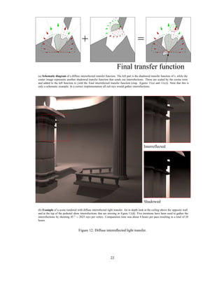
    Again, examples can be found in figures 12(a) and 12(b).

6.2.4 Light functions
A light function maps a direction ω to a light intensity. It is usually described using the three RGB color
channels. Light function are very similar to the environment maps described before and those can actually
be used as light functions. But computing and pre-filtering environment maps at real-time is problematic
at the moment and therefore approximations are often used. For example, in a demo a dynamically tinted
environment map is used for skybox rendering while the light function is just a quick, dirty and scripted
approximation of sunlight that was heavily tweaked until it fitted well enough. It uses a colored directional


                                                                      21
+                                                =
PSfrag replacements
                                                                                          Final transfer function
                      (a) Schematic diagram of a diffuse interreflected transfer function. The left part is the shadowed transfer function of x, while the
                      center image represents another shadowed transfer function that sends out interreflections. These are scaled by the cosine term
                      and added to the left function to yield the final interreflected transfer function (cmp. figures 11(a) and 11(c)). Note that this is
                      only a schematic example. In a correct implementation all red rays would gather interreflections.


                                                                                                                 Interreflected


                                                                                                                 Shadowed

                      (b) Example of a scene rendered with diffuse interreflected light transfer. An in depth look at the ceiling above the opposite wall
                      and at the top of the pedestal show interreflections that are missing in figure 11(d). Five iterations have been used to gather the
                      interreflections by shooting 45 2 = 2025 rays per vertex. Computation time was about 4 hours per pass resulting in a total of 20
                      hours.


                                                         Figure 12: Diffuse interreflected light transfer.


                                                                                    22
light projected into spherical harmonic coefficients for the sun and a slightly blueish ambient term that
is distributed equally into all directions (to fake the light refractions by the atmosphere and the nightly
illumination by the moon). The ambient term can be realized with spherical harmonics by simply scaling
the zeroth spherical harmonic order basis function (since it represents equal distribution into all directions).
    To simulate the movement of the sun the light function is brought into the proper rotation using the
aforementioned ZYZ-Euler operation described above. The color channels are also modified to simulate
dusk and dawn.
    More information on approximating sunlight can be found in Green’s paper.


7 Conclusion
This work has presented some orthogonal basis functions, and how they can be combined to form the
spherical harmonics. Also, some properties of the spherical harmonics have been discussed and examples
of how they can be used have been given. While the intention was to explain the spherical harmonic as
simple and illuminating as possible, it still is not trivial - both to write and explain as well as to understand.
Hopefully it has become clear what spherical harmonics can be used for in computer graphics, although
only two of the plentiful number of applications could be illustrated here . It has yet to be determined what
else those little adaptive spherical shaped friends can be used for - not only in computer graphics, but also
computer vision (as Basri and Jacobs have shown [4]) and maybe other graphics related areas like collision
detection, artificial intelligence, and more.


References
[1] B. Cabral, N. Max and R. Springmeyer. Bidirectional Reflection Functions from Surface Bump Maps
    SIGGRAPH 273-281, 1987
[2] M. D’Zmura. Shading Ambiguity: Reflection and Illumination. In Computational Models of Visual
    Processing Landy and Movshon, eds., MIT Press, Cambridge, 187-207, 1991
[3] Ravi Ramamoorthi, Pat Hanrahan. An Efficient Representation for Irradiance Environment Maps SIG-
    GRAPH 497-500, 2001
[4] Ronen Basri, David W. Jacobs. Lambertian Reflectance and Linear Subspaces IEEE Transactions on
    Pattern Analysis and Machine Intelligence Vol. 25 2001
[5] Richard P. Feynman. The Feynman Lectures on Physics, vol. I - part 1. Inter European Editions, Ams-
    terdam 1975
[6] Eric W. Weisstein. MathWorld http://mathworld.wolfram.com/
[7] W. Magnus, F. Oberhettinger, R.P. Soni. Formulas and Theorems for the Special Functions of Mathe-
    matical Physics Chapter V, pp 204, New York 1966
[8] F. Sillion, J. Arvo, S. Westin and D. Greenberg. A Global Illumination Solution for General Reflectance
    Distributions SIGGRAPH 187-196. 1991
[9] S. Westin, J. Arvo, K. and Torrance. Predicting Reflectance Functions from Complex Surfaces SIG-
    GRAPH 255-264, 1992
[10] State of the Art in Monte Carlo Ray Tracing SIGGRAPH Course 29,2001
[11] Peter Shirley. Realistic Ray Tracing A. K. Peters 2001
[12] Robin Green. Spherical Harmonic Lighting: The Gritty Details SCEA Research and Development,
    2003
[13] Matt Pharr. Physically Based Rendering: From Theory to Implementation Morgan Kaufman, July
    2004


                                                       23
[14] Numerical Methods in C: The Art of Scientific Computing Cambridge University Press, pp 252-254,
    1992
[15] Paul Devebec. Light Probe Image Gallery

[16] Peter-Pike Sloan, Jan Kautz, John Snyder. Precomputed Radiance Transfer for Real-Time Rendering
    in Dynamic, Low-Frequency Lighting Environments Microsoft Research and SIGGRAPH, July 2002
[17] Jan Kautz, Peter-Pike Sloan and John Snyder. Fast Arbitrary BRDF Shading for Low-Frequency Light-
    ing Using Spherical Harmonics 13th Eurographics Workshop on Rendering, 2002
[18] J. Ivanic and K. Ruedenberg. Rotation Matrices for Real Spherical Harmonics, Direct Determination
    by Recursion Journal of Physical Chemistry A Vol. 100, pp 6342-6347, 1996

[19] J. Ivanic and K. Ruedenberg. Additions and Corrections: Rotation Matrices for Real Spherical Har-
    monics Journal of Physical Chemistry A Vol. 102, No. 45, pp 9099-9100, 1998
[20] Cheol Ho Choi et al. Rapid and stable determination of rotation matrices between spherical harmonics
    by direct recursion Journal of Chemical Physics Vol 111, No. 19, pp 8825-8832, 1999
[21] Miguel A. Blanco, M. Florenz, M. Bermejo. Evaluation of the rotation matrices in the basis of real
    spherical harmonics Journal of Molecular Structure (Theochem), 419, pp 19-27, 1997

[22] J.T. Kajiya. The Rendering Equation SIGGRAPH, pp 134-150, 1986
[23] Garry McTaggart. Half-Life 2 / Source Shading Game Developers Conference, 2005
[24] Cohen and Wallace. Radiosity and Realistic Image Synthesis Academic Press, 1993


                                                   24
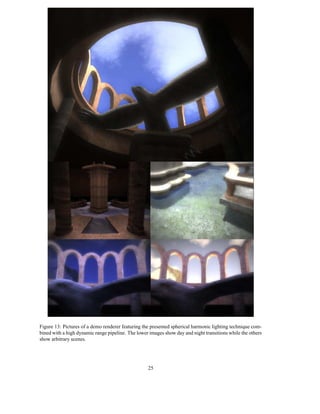
Figure 13: Pictures of a demo renderer featuring the presented spherical harmonic lighting technique com-
bined with a high dynamic range pipeline. The lower images show day and night transitions while the others
show arbitrary scenes.


                                                   25

More Related Content

Viewers also liked

New members 10.14.15
New members 10.14.15New members 10.14.15
New members 10.14.15TLMI
 
Treamentsheet 1
Treamentsheet 1Treamentsheet 1
Treamentsheet 1Serena Chu
 
The pre algebra math fair and family activity project
The pre algebra math fair and family activity projectThe pre algebra math fair and family activity project
The pre algebra math fair and family activity projectPam Hager
 
The Flick
The FlickThe Flick
The Flickhbwmike
 
Varam arnis sults
Varam arnis sultsVaram arnis sults
Varam arnis sultsegilsdo
 
Primero san-dimas-site-visit-sept v001-o70rly
Primero san-dimas-site-visit-sept v001-o70rlyPrimero san-dimas-site-visit-sept v001-o70rly
Primero san-dimas-site-visit-sept v001-o70rlyprimero_mining
 
Ultra sound technician
Ultra sound technicianUltra sound technician
Ultra sound technicianmartyalvarado
 
Merry Christmas
Merry ChristmasMerry Christmas
Merry Christmashbwmike
 
New microsoft office word 97 2003 document
New microsoft office word 97   2003 documentNew microsoft office word 97   2003 document
New microsoft office word 97 2003 documentlun212009
 
Curro jse showcase september 2011
Curro jse showcase   september 2011Curro jse showcase   september 2011
Curro jse showcase september 2011Curroholdings
 

Viewers also liked (20)

Presentazione incontro IFF 14/11/2011
Presentazione incontro IFF 14/11/2011Presentazione incontro IFF 14/11/2011
Presentazione incontro IFF 14/11/2011
 
New members 10.14.15
New members 10.14.15New members 10.14.15
New members 10.14.15
 
Treamentsheet 1
Treamentsheet 1Treamentsheet 1
Treamentsheet 1
 
Masalah lingkungan
Masalah lingkunganMasalah lingkungan
Masalah lingkungan
 
Business Strategy
Business StrategyBusiness Strategy
Business Strategy
 
The pre algebra math fair and family activity project
The pre algebra math fair and family activity projectThe pre algebra math fair and family activity project
The pre algebra math fair and family activity project
 
The Flick
The FlickThe Flick
The Flick
 
ISLAS CANARIAS
ISLAS CANARIASISLAS CANARIAS
ISLAS CANARIAS
 
Varam arnis sults
Varam arnis sultsVaram arnis sults
Varam arnis sults
 
Bigsmallong
BigsmallongBigsmallong
Bigsmallong
 
Primero san-dimas-site-visit-sept v001-o70rly
Primero san-dimas-site-visit-sept v001-o70rlyPrimero san-dimas-site-visit-sept v001-o70rly
Primero san-dimas-site-visit-sept v001-o70rly
 
Ultra sound technician
Ultra sound technicianUltra sound technician
Ultra sound technician
 
Merry Christmas
Merry ChristmasMerry Christmas
Merry Christmas
 
Q3 2013 report final
Q3 2013 report finalQ3 2013 report final
Q3 2013 report final
 
New microsoft office word 97 2003 document
New microsoft office word 97   2003 documentNew microsoft office word 97   2003 document
New microsoft office word 97 2003 document
 
ARLA BLUE AIR
ARLA BLUE AIRARLA BLUE AIR
ARLA BLUE AIR
 
Curro jse showcase september 2011
Curro jse showcase   september 2011Curro jse showcase   september 2011
Curro jse showcase september 2011
 
Projects
ProjectsProjects
Projects
 
DoItSocial - Cómo funciona?
DoItSocial - Cómo funciona?DoItSocial - Cómo funciona?
DoItSocial - Cómo funciona?
 
Uu 32 tahun 2009 (pplh)
Uu 32 tahun 2009 (pplh)Uu 32 tahun 2009 (pplh)
Uu 32 tahun 2009 (pplh)
 

Similar to spherical-harmonic-lighting

Similar to spherical-harmonic-lighting (20)

Rapport de stage: Optimisation d'une starshade
Rapport de stage: Optimisation d'une starshadeRapport de stage: Optimisation d'une starshade
Rapport de stage: Optimisation d'une starshade
 
Queueing 3
Queueing 3Queueing 3
Queueing 3
 
Queueing
QueueingQueueing
Queueing
 
Queueing 2
Queueing 2Queueing 2
Queueing 2
 
Reconstruction of Surfaces from Three-Dimensional Unorganized Point Sets / Ro...
Reconstruction of Surfaces from Three-Dimensional Unorganized Point Sets / Ro...Reconstruction of Surfaces from Three-Dimensional Unorganized Point Sets / Ro...
Reconstruction of Surfaces from Three-Dimensional Unorganized Point Sets / Ro...
 
genral physis
genral physisgenral physis
genral physis
 
Cliff sugerman
Cliff sugermanCliff sugerman
Cliff sugerman
 
Computer Graphics Notes.pdf
Computer Graphics Notes.pdfComputer Graphics Notes.pdf
Computer Graphics Notes.pdf
 
Calculus
CalculusCalculus
Calculus
 
7 introplasma
7 introplasma7 introplasma
7 introplasma
 
Grafx
GrafxGrafx
Grafx
 
Climb - A Generic and Dynamic Approach to Image Processing
Climb - A Generic and Dynamic Approach to Image ProcessingClimb - A Generic and Dynamic Approach to Image Processing
Climb - A Generic and Dynamic Approach to Image Processing
 
Superduper4#1
Superduper4#1Superduper4#1
Superduper4#1
 
Superduper4#2
Superduper4#2Superduper4#2
Superduper4#2
 
R intro
R introR intro
R intro
 
Superduper4#1
Superduper4#1Superduper4#1
Superduper4#1
 
Superduper4#1
Superduper4#1Superduper4#1
Superduper4#1
 
Superduper4#1
Superduper4#1Superduper4#1
Superduper4#1
 
Superduper4#2
Superduper4#2Superduper4#2
Superduper4#2
 
foobar
foobarfoobar
foobar
 

Recently uploaded

How to Troubleshoot Apps for the Modern Connected Worker
How to Troubleshoot Apps for the Modern Connected WorkerHow to Troubleshoot Apps for the Modern Connected Worker
How to Troubleshoot Apps for the Modern Connected WorkerThousandEyes
 
Tata AIG General Insurance Company - Insurer Innovation Award 2024
Tata AIG General Insurance Company - Insurer Innovation Award 2024Tata AIG General Insurance Company - Insurer Innovation Award 2024
Tata AIG General Insurance Company - Insurer Innovation Award 2024The Digital Insurer
 
2024: Domino Containers - The Next Step. News from the Domino Container commu...
2024: Domino Containers - The Next Step. News from the Domino Container commu...2024: Domino Containers - The Next Step. News from the Domino Container commu...
2024: Domino Containers - The Next Step. News from the Domino Container commu...Martijn de Jong
 
Connector Corner: Accelerate revenue generation using UiPath API-centric busi...
Connector Corner: Accelerate revenue generation using UiPath API-centric busi...Connector Corner: Accelerate revenue generation using UiPath API-centric busi...
Connector Corner: Accelerate revenue generation using UiPath API-centric busi...DianaGray10
 
From Event to Action: Accelerate Your Decision Making with Real-Time Automation
From Event to Action: Accelerate Your Decision Making with Real-Time AutomationFrom Event to Action: Accelerate Your Decision Making with Real-Time Automation
From Event to Action: Accelerate Your Decision Making with Real-Time AutomationSafe Software
 
presentation ICT roal in 21st century education
presentation ICT roal in 21st century educationpresentation ICT roal in 21st century education
presentation ICT roal in 21st century educationjfdjdjcjdnsjd
 
The 7 Things I Know About Cyber Security After 25 Years | April 2024
The 7 Things I Know About Cyber Security After 25 Years | April 2024The 7 Things I Know About Cyber Security After 25 Years | April 2024
The 7 Things I Know About Cyber Security After 25 Years | April 2024Rafal Los
 
GenAI Risks & Security Meetup 01052024.pdf
GenAI Risks & Security Meetup 01052024.pdfGenAI Risks & Security Meetup 01052024.pdf
GenAI Risks & Security Meetup 01052024.pdflior mazor
 
Understanding Discord NSFW Servers A Guide for Responsible Users.pdf
Understanding Discord NSFW Servers A Guide for Responsible Users.pdfUnderstanding Discord NSFW Servers A Guide for Responsible Users.pdf
Understanding Discord NSFW Servers A Guide for Responsible Users.pdfUK Journal
 
Boost Fertility New Invention Ups Success Rates.pdf
Boost Fertility New Invention Ups Success Rates.pdfBoost Fertility New Invention Ups Success Rates.pdf
Boost Fertility New Invention Ups Success Rates.pdfsudhanshuwaghmare1
 
AWS Community Day CPH - Three problems of Terraform
AWS Community Day CPH - Three problems of TerraformAWS Community Day CPH - Three problems of Terraform
AWS Community Day CPH - Three problems of TerraformAndrey Devyatkin
 
Data Cloud, More than a CDP by Matt Robison
Data Cloud, More than a CDP by Matt RobisonData Cloud, More than a CDP by Matt Robison
Data Cloud, More than a CDP by Matt RobisonAnna Loughnan Colquhoun
 
Finology Group – Insurtech Innovation Award 2024
Finology Group – Insurtech Innovation Award 2024Finology Group – Insurtech Innovation Award 2024
Finology Group – Insurtech Innovation Award 2024The Digital Insurer
 
Bajaj Allianz Life Insurance Company - Insurer Innovation Award 2024
Bajaj Allianz Life Insurance Company - Insurer Innovation Award 2024Bajaj Allianz Life Insurance Company - Insurer Innovation Award 2024
Bajaj Allianz Life Insurance Company - Insurer Innovation Award 2024The Digital Insurer
 
GenCyber Cyber Security Day Presentation
GenCyber Cyber Security Day PresentationGenCyber Cyber Security Day Presentation
GenCyber Cyber Security Day PresentationMichael W. Hawkins
 
How to Troubleshoot Apps for the Modern Connected Worker
How to Troubleshoot Apps for the Modern Connected WorkerHow to Troubleshoot Apps for the Modern Connected Worker
How to Troubleshoot Apps for the Modern Connected WorkerThousandEyes
 
Strategies for Unlocking Knowledge Management in Microsoft 365 in the Copilot...
Strategies for Unlocking Knowledge Management in Microsoft 365 in the Copilot...Strategies for Unlocking Knowledge Management in Microsoft 365 in the Copilot...
Strategies for Unlocking Knowledge Management in Microsoft 365 in the Copilot...Drew Madelung
 
Tech Trends Report 2024 Future Today Institute.pdf
Tech Trends Report 2024 Future Today Institute.pdfTech Trends Report 2024 Future Today Institute.pdf
Tech Trends Report 2024 Future Today Institute.pdfhans926745
 
Strategies for Landing an Oracle DBA Job as a Fresher
Strategies for Landing an Oracle DBA Job as a FresherStrategies for Landing an Oracle DBA Job as a Fresher
Strategies for Landing an Oracle DBA Job as a FresherRemote DBA Services
 
[2024]Digital Global Overview Report 2024 Meltwater.pdf
[2024]Digital Global Overview Report 2024 Meltwater.pdf[2024]Digital Global Overview Report 2024 Meltwater.pdf
[2024]Digital Global Overview Report 2024 Meltwater.pdfhans926745
 

Recently uploaded (20)

How to Troubleshoot Apps for the Modern Connected Worker
How to Troubleshoot Apps for the Modern Connected WorkerHow to Troubleshoot Apps for the Modern Connected Worker
How to Troubleshoot Apps for the Modern Connected Worker
 
Tata AIG General Insurance Company - Insurer Innovation Award 2024
Tata AIG General Insurance Company - Insurer Innovation Award 2024Tata AIG General Insurance Company - Insurer Innovation Award 2024
Tata AIG General Insurance Company - Insurer Innovation Award 2024
 
2024: Domino Containers - The Next Step. News from the Domino Container commu...
2024: Domino Containers - The Next Step. News from the Domino Container commu...2024: Domino Containers - The Next Step. News from the Domino Container commu...
2024: Domino Containers - The Next Step. News from the Domino Container commu...
 
Connector Corner: Accelerate revenue generation using UiPath API-centric busi...
Connector Corner: Accelerate revenue generation using UiPath API-centric busi...Connector Corner: Accelerate revenue generation using UiPath API-centric busi...
Connector Corner: Accelerate revenue generation using UiPath API-centric busi...
 
From Event to Action: Accelerate Your Decision Making with Real-Time Automation
From Event to Action: Accelerate Your Decision Making with Real-Time AutomationFrom Event to Action: Accelerate Your Decision Making with Real-Time Automation
From Event to Action: Accelerate Your Decision Making with Real-Time Automation
 
presentation ICT roal in 21st century education
presentation ICT roal in 21st century educationpresentation ICT roal in 21st century education
presentation ICT roal in 21st century education
 
The 7 Things I Know About Cyber Security After 25 Years | April 2024
The 7 Things I Know About Cyber Security After 25 Years | April 2024The 7 Things I Know About Cyber Security After 25 Years | April 2024
The 7 Things I Know About Cyber Security After 25 Years | April 2024
 
GenAI Risks & Security Meetup 01052024.pdf
GenAI Risks & Security Meetup 01052024.pdfGenAI Risks & Security Meetup 01052024.pdf
GenAI Risks & Security Meetup 01052024.pdf
 
Understanding Discord NSFW Servers A Guide for Responsible Users.pdf
Understanding Discord NSFW Servers A Guide for Responsible Users.pdfUnderstanding Discord NSFW Servers A Guide for Responsible Users.pdf
Understanding Discord NSFW Servers A Guide for Responsible Users.pdf
 
Boost Fertility New Invention Ups Success Rates.pdf
Boost Fertility New Invention Ups Success Rates.pdfBoost Fertility New Invention Ups Success Rates.pdf
Boost Fertility New Invention Ups Success Rates.pdf
 
AWS Community Day CPH - Three problems of Terraform
AWS Community Day CPH - Three problems of TerraformAWS Community Day CPH - Three problems of Terraform
AWS Community Day CPH - Three problems of Terraform
 
Data Cloud, More than a CDP by Matt Robison
Data Cloud, More than a CDP by Matt RobisonData Cloud, More than a CDP by Matt Robison
Data Cloud, More than a CDP by Matt Robison
 
Finology Group – Insurtech Innovation Award 2024
Finology Group – Insurtech Innovation Award 2024Finology Group – Insurtech Innovation Award 2024
Finology Group – Insurtech Innovation Award 2024
 
Bajaj Allianz Life Insurance Company - Insurer Innovation Award 2024
Bajaj Allianz Life Insurance Company - Insurer Innovation Award 2024Bajaj Allianz Life Insurance Company - Insurer Innovation Award 2024
Bajaj Allianz Life Insurance Company - Insurer Innovation Award 2024
 
GenCyber Cyber Security Day Presentation
GenCyber Cyber Security Day PresentationGenCyber Cyber Security Day Presentation
GenCyber Cyber Security Day Presentation
 
How to Troubleshoot Apps for the Modern Connected Worker
How to Troubleshoot Apps for the Modern Connected WorkerHow to Troubleshoot Apps for the Modern Connected Worker
How to Troubleshoot Apps for the Modern Connected Worker
 
Strategies for Unlocking Knowledge Management in Microsoft 365 in the Copilot...
Strategies for Unlocking Knowledge Management in Microsoft 365 in the Copilot...Strategies for Unlocking Knowledge Management in Microsoft 365 in the Copilot...
Strategies for Unlocking Knowledge Management in Microsoft 365 in the Copilot...
 
Tech Trends Report 2024 Future Today Institute.pdf
Tech Trends Report 2024 Future Today Institute.pdfTech Trends Report 2024 Future Today Institute.pdf
Tech Trends Report 2024 Future Today Institute.pdf
 
Strategies for Landing an Oracle DBA Job as a Fresher
Strategies for Landing an Oracle DBA Job as a FresherStrategies for Landing an Oracle DBA Job as a Fresher
Strategies for Landing an Oracle DBA Job as a Fresher
 
[2024]Digital Global Overview Report 2024 Meltwater.pdf
[2024]Digital Global Overview Report 2024 Meltwater.pdf[2024]Digital Global Overview Report 2024 Meltwater.pdf
[2024]Digital Global Overview Report 2024 Meltwater.pdf
 

spherical-harmonic-lighting

  • 1. Spherical Harmonics Volker Schönefeld 1st July 2005 Contents 1 Introduction 2 2 Overview 2 3 Orthogonal functions 2 3.1 Associated Legendre Polynomials . . . . . . . . . . . . . . . . . . . . . . . . . . . . . . 4 3.2 Sine and Cosine . . . . . . . . . . . . . . . . . . . . . . . . . . . . . . . . . . . . . . . . 5 4 Spherical functions 6 4.1 Spherical polar coordinates . . . . . . . . . . . . . . . . . . . . . . . . . . . . . . . . . . 6 4.2 Definition . . . . . . . . . . . . . . . . . . . . . . . . . . . . . . . . . . . . . . . . . . . 6 5 Spherical Harmonics 7 5.1 Definition . . . . . . . . . . . . . . . . . . . . . . . . . . . . . . . . . . . . . . . . . . . 7 5.2 Properties . . . . . . . . . . . . . . . . . . . . . . . . . . . . . . . . . . . . . . . . . . . 11 5.2.1 Harmonic expansion . . . . . . . . . . . . . . . . . . . . . . . . . . . . . . . . . 11 5.2.2 Convolution . . . . . . . . . . . . . . . . . . . . . . . . . . . . . . . . . . . . . . 12 5.2.3 Rotational invariance . . . . . . . . . . . . . . . . . . . . . . . . . . . . . . . . . 12 5.2.4 Fast Integration . . . . . . . . . . . . . . . . . . . . . . . . . . . . . . . . . . . . 12 5.2.5 Transfer Matrix . . . . . . . . . . . . . . . . . . . . . . . . . . . . . . . . . . . . 13 5.3 Rotation . . . . . . . . . . . . . . . . . . . . . . . . . . . . . . . . . . . . . . . . . . . . 13 6 Spherical Harmonics in Computer Graphics 14 6.1 Irradiance Environment Maps . . . . . . . . . . . . . . . . . . . . . . . . . . . . . . . . 14 6.2 Spherical Harmonic Lighting . . . . . . . . . . . . . . . . . . . . . . . . . . . . . . . . . 17 6.2.1 Introduction . . . . . . . . . . . . . . . . . . . . . . . . . . . . . . . . . . . . . . 17 6.2.2 The new algorithm . . . . . . . . . . . . . . . . . . . . . . . . . . . . . . . . . . 17 6.2.3 Transfer functions . . . . . . . . . . . . . . . . . . . . . . . . . . . . . . . . . . 19 6.2.4 Light functions . . . . . . . . . . . . . . . . . . . . . . . . . . . . . . . . . . . . 21 7 Conclusion 23
  • 2. 1 Introduction Just as the Fourier basis represents an important tool for evaluation of convolutions in a one- or two dimen- sional space, the spherical harmonic basis is a similar tool but defined on the surface of a sphere. Spherical harmonics have already been used in the field of computer graphics, especially to model BRDF and inci- dent radiance as well as BRDF inference [1, 2, 3, 8, 9]. But spherical harmonics have just recently become feasible to be used in real time computer graphics, especially in enhancing the dynamic lighting of scenes in real time as will be shown later in this work. The motivation of this pro-seminar is to demystify spherical harmonics in a similar way as Robin Green did [12] but with more mathematical background on the functions themselves and less focus on the actual applications, which in Green’s case was a technique called spherical harmonic lighting. Although the spherical harmonics are not the easiest mathematical functions this is an attempt at ex- plaining and illustrating them as plausible as possible - without leaving out the critical mathematical rela- tionships. Spherical harmonics are sometimes called the swiss army knife of mathematical physics and this metaphor is extensible to computer graphics to a certain degree, as the attentive reader will hopefully understand at the end of this work. 2 Overview First the required mathematical fundamentals will be reviewed. This includes a short evaluation of or- thogonal functions, where the associated Legendre polynomials will be introduced and the sine and cosine functions will be examined regarding some intriguing properties. Thereafter spherical functions and spher- ical polar coordinates will be reviewed shortly. Once the fundamentals are in place they are followed by a definition of the spherical harmonic basis while evaluating its most important properties. Finally the focus will move on examples for the usage of spherical harmonics to solve the common lighting function in a rather new and partially precomputed way. Also, the use of spherical harmonics to quickly relight objects using pre-filtered irradiance environment maps will be discussed. 3 Orthogonal functions Orthogonal functions [6, 7] are classes of functions {pn (x)} that obey an orthogonality relation over their domain [a, b]: Z b w(x)pn (x)pm (x)dx = cn δnm = cm δnm (1) a and Z b w(x)pn (x)pm (x)dx = cn δnm = cm δnm (2) a for real- and complex-valued functions respectively. δkl denotes the Kronecker delta [6], defined by 1 k=l δkl = . 0 k=l w(x) is an arbitrary weighting function independent of n as well as m and φ = ℜ(φ) − iℑ(φ) denotes the complex conjugate of the complex number φ. With this property p n (x) is then called a basis function. If cn = 1 for all n the class is even orthonormal, which is a stronger relation and provides some additional properties. Amongst other things orthogonal and orthonormal basis functions allow the expression of any piecewise continuous function over [a, b] as a linear combination of an infinite series of linearly independent basis functions. In other words: The basis functions pn are small pieces of information. Scaling and combining them produces either exactly the original function f (if an infinite series of basis functions is used or the function is band-limited) or a band-limited approximation f˜ of the source function (if only a finite number of basis 2
  • 3. × R × = k0 = 0.3 k0 = + R k1 × = × = k1 = −0.2 + PSfrag replacements k2 × = R PSfrag replacements × = k2 = 0.4 k3 × = + R = × = k3 = 0.7 f (x)= = (a) Projection of the red polynomial into the first few Legendre coef- (b) Reconstruction of the original function by ficients kn . summing the scaled basis functions. Figure 1: An example of an expansion and reconstruction of f (x) = 1.75x 3 + 0.6x2 + 0.21x − 0.06 using the first four Legendre polynomials 1, x, 1 (3x2 − 1) and 1 (5x3 − 3x). 2 2 functions is used while the source function also consists of signals of higher frequency than the threshold). Band-limiting means that frequencies higher than a certain threshold are removed and this is similar to a low-pass filter applied on the function before the harmonic expansion. For the approximation the maximum error max f˜(x) − f (x) (3) x is in general proportional to the number of basis functions used. Projection and Reconstruction: So everything needed to approximate a given function f arbitrarily accurate is to compute the coefficients kn describing how much each basis function pn is like f . This is done by integrating the product Z f (x)pn (x)dx = kn (4) over the full domain of f . The aforementioned process is called projection or expansion. An example is shown in figure 1(a). Its inverse process is defined as the linear combination of all basis functions scaled by their associated coefficients ∞ N f (x) = ∑ kn p n or f˜(x) = ∑ kn p n (5) n=0 n=0 This is called reconstruction and it is demonstrated in figure 1(b). Integration of orthonormal series: In addition to the orthogonal set of properties an important property of the orthonormal functions is the following: Consider the integral of a product of any two arbitrary piecewise continuous functions a(x) and b(x). Z a(x)b(x)dx = ? (6) 3
  • 4. ˜ Expanding these functions into band-limited functions a and b with coefficients an and bn respectively ˜ transforms the integral into a simple dot product of the projection coefficients. Z N a(x)b(x)dx = ∑ an bn . ˜ ˜ (7) i=0 This effectively reduces a symbolic integration of the product of two functions into a series of multiply-adds which are a lot easier to compute. Numerical Integration: When evaluating integrals for harmonic expansion (e.g. an integral of a function that describes the incident light intensity for an given point in a complex scene), instead of performing sym- bolic integration it is often necessary to use other solutions - especially in the field of numerical computer simulation. One such solution is called the Monte Carlo Integration. It basically consists of taking a num- ber of samples of the function (probabilistic gathering) and using them to approximate the correct integral result. The more samples are taken the less error is introduced in this integration. One keyword that is used later on when computing spherical harmonic coefficients is known as the Monte Carlo Estimator and it is defined as 1 N Z f (x) ≈ ∑ f (xi )w(xi ) (8) N i=1 where f denotes the function we want to integrate, N the number of samples, f (x i ) represents one sample and w(xi ) represents a weighting function for each sample, which is its reciprocal probability. More information on the topic can be found here [6, 10, 11, 13]. Examples: A prominent example that makes use of the orthogonality relationship is the Fourier series [6], which provides a convenient method of expanding periodic functions into an infinite sum of sines and cosines. There will be more details on the sine and cosine orthogonality later in this section since they are one of the fundamentals spherical harmonics are built upon. Additionally a class of orthogonal polynomials will be analyzed, named the associated Legendre polynomials. They are often interconnected with and will be used to define as well as explore the spherical harmonics. 3.1 Associated Legendre Polynomials The first class of orthogonal functions is named after Adrien-Marie Legendre (1752-1833), a french math- ematician. In general represented by the symbol Plm the associated Legendre polynomials are real-valued and defined over the range [−1, 1]. An explicit definition is (−1)m d l+m 2 Plm = (1 − x2)m (x − 1)l (9) 2l l! dxl+m although it is rarely used for computational purposes, because the evaluation is tricky and numerically unstable. The function takes two integer arguments l and m which are constrained by l ∈ N 0 and m ∈ [0, l]. l is used as the band index to divide the class into bands of functions resulting in a total of (l + 1)l polynomials for a l-th band series. With respect to l and w(x) = 1 the associated Legendre polynomials obey the orthogonality relationship Z 1 2(l + m)! Plm (x)Plm (x)dx = δll . (10) −1 (2l + 1)(l − m)! However, for different m on the same band, the polynomials are orthogonal with respect to a different constant and another weighting function. If neither m = m nor l = l the polynomials are not orthogonal at all. When used in spherical harmonics, this orthogonality needs to be established by another orthogonal polynomial. For a better understanding the first few functions are shown in figure 3.1 and used for the harmonic expansion in figures 1(a), 1(b) with l = 0..3 and m = 0. If m = 0, as it can be found in the aforementioned 4
  • 5. l m Pm (x) l 2 P3 (x) 0 0 1 2 P2 (x) 1 0 x √ 1 1 1 − 1 − x2 P3 (x) 0 P0 (x) 1 2 1 2 0 2 (3x − 1) 0 P3 (x) 0 P1 (x) √ −0.5 0.5 2 1 −3x 1 − x2 0 P2 (x) 2 2 3(1 − x2 ) 1 P1 (x) −1 1 P2 (x) 1 3 3 0 2 (5x − 3x) 3 √ 3 1 2 (1 − 5x2 ) 1 − x2 3 P3 (x) 3 2 15x(1 − x2 ) 3 3 −15 (1 − x2 )3 Figure 2: First four bands l = 0, ..., 3 of the associated Legendre polynomials example, they degenerate to the unassociated Legendre polynomials, which will however not be discussed in this work. The associated Legendre polynomials can also be defined using a set of recurrence relations m Pm (x) = (−1)m (2m − 1)!!(1 − x2)m/2 (11) m m Pm+1 (x) = x(2m + 1)Pm (x) (12) (l − m)Plm (x) m m = x(2l − 1)Pl−1(x) − (l + m − 1)Pl−2(x) (13) which will come in handy when implementing the function in a computer application, especially since they are easier to compute and less susceptible to numerical errors compared to other methods [6, 14]. To evaluate a given function value Plm (x) primarily equation (11) is used to generate the highest Pm possible. m Thereafter for l = m the correct value has been computed. Otherwise all that is left to do is to raise the band, so (12) is used once to get to the next band, and then (13) can be iterated (because it depends on l − 1 and l − 2 results the second rule needs to be applied once) until the correct answer is found. 3.2 Sine and Cosine The other important set of orthogonal functions is the sine and cosine set. Despite being the key func- tions when talking of spherical or circular systems, they also obey the orthogonality relation over [−π, π]. Following key integral identities can be defined, and will be of good use when defining spherical harmonics: Z π sin(mx) sin(nx)dx = πδmn (14) −π Z π cos(mx) cos(nx)dx = πδmn −π Z π sin(mx) cos(nx)dx = 0 −π Z π Z π sin(mx)dx = cos(mx)dx = 0 −π −π whereas m, n = 0 are called phases. As noted above, these integral identities are one of the key properties the Fourier Series is built upon. 5
  • 6. Another important property of the sine and cosine functions is related to the complex numbers. It is called the Euler identity and defined as eiφ = cos(φ) + i sin(φ). (15) For more information, see [6, 5]. 4 Spherical functions Now the key fundamentals for the main topic are defined and explained. But before this work jumps into the colorful world of spherical harmonics, there are some small conventions that need to be reviewed in order to ensure a proper understanding. 4.1 Spherical polar coordinates When talking about spherical functions it is convenient to use spherical polar z coordinates instead of the Cartesian ones. The spherical coordinate system is PSfrag replacements defined by two angles θ and φ, whereas 0 ≤ φ < 2π describes the azimuthal angle θ r in the xy-plane originating at the x-axis and 0 ≤ θ < π denotes the polar angle y φ from the z-axis. Additionally a radius r is used to represent the distance from the x origin of the coordinate system, but it can be omitted for normalized coordinates, which all lie on a unit sphere and therefore have a uniform distance from the origin of r = 1. See figure 3. Care has to be taken when comparing spherical Figure 3: Polar coordi- functions from different sources, since there is no generally accepted convention nate system about the semantics of φ and θ, thus they may be swapped or defined differently. The relations between a point in the Cartesian and spherical polar coordinate systems for this work are defined as r = x2 + y2 + z2 (16) y φ = cot (17) x x2 + y2 z θ = sin−1 = cos−1 (18) r r and analogously the inverse relations x = r cos φ sin θ (19) y = r sin φ sin θ (20) z = r cos θ. (21) 4.2 Definition A spherical function is a mapping of spherical coordinates (θ, φ) to a scalar value. In this work spherical functions are assumed to be real-valued, although complex-valued functions can be harmonically expanded by the complex spherical harmonics series analogously. Spherical functions can easily be visualized by either displaying a textured sphere, where the intensity of a point on the surface represents the value of the function at that point (Figure 4(b)), or by displacing the points on the surface of the sphere along their corresponding normal vector based on the value of the function (Figure 4(a)). An integration can be thought of as summing infinitesimal patches of area. The parameterization of a sphere using polar coordinates causes the patches on the equator to be bigger and thus should have more influence on the solution of the integral compared to the patches at the poles. To encode this effect an integration of a spherical function is pre-multiplied by sin(θ) which is 1 at the equator, vanishes at the poles and is directly proportional to the area of the patches (which only depends on θ). To enhance readability, 6
  • 7. (a) Displaced unit sphere with random coloriza- (b) Textured unit sphere, using the spectrum shown on tion. the right side to visualize high and low function values. Figure 4: An exemplary spherical function f (θ, φ) = 1 (cos(6φ)3 + sin(θ)4 + 1) plotted with both presented 4 techniques. such an integration of a spherical function f (θ, φ) over the surface of a unit sphere S will be expressed either in the explicit spherical coordinate form or as an integral over the implicit surface S. Z 2π Z π Z f (θ, φ) sin(θ)dθdφ = f (ω)dω (22) 0 0 S Analogously, an integral over the surface of an hemisphere Ω(n) in direction n is denoted as Z 2π Z π Z f (θ, φ) sin(θ)h(n, θ, φ)dθdφ = f (ω)dω (23) 0 0 Ω(n) whereas 1 0 ≤ n · vθφ h(n, θ, φ) = 0 otherwise with vθφ being the vector from the center of the unit-sphere to the point described by θ and φ. Additionally later on xω will be used to describe any point in direction ω. 5 Spherical Harmonics Now we finally arrived at the actual topic of this work and the spherical harmonics are very close. With all the required fundamentals defined now a formal write up and explanation of the definition of the spherical harmonics will follow. After that details of the important properties that result from this definition will be discussed. Finally rotation of a spherical harmonic function are described briefly. 5.1 Definition In section 3 it is shown that the associated Legendre polynomials can be used to express any piecewise continuous function over the interval [−1, 1] either as an infinite series of polynomials, a finite series of polynomials for a band-limited approximation or a finite series of polynomials in case the function itself does not have frequencies higher than a certain threshold. When looking at the definition of spherical 7
  • 8. coordinates in section 4 it may become obvious that we can express any circularly symmetric function (like l = 2, m = 0 in figure 6), which has no dependence on φ, in terms of the associated Legendre polynomial by mapping θ into the [−1, 1] domain using cos θ. But we need some mechanism to provide orthogonality in case of non-circular symmetric functions. This can be realized by combining the associated Legendre polynomials for the θ dependence with the sine and cosine functions for the φ dependent part. Now with the basic idea explained a formal description of the spherical harmonics will follow and finally they will be investigated. A complete formal definition of the complex-valued spherical harmonic series with two arguments l ∈ N0 and −l ≤ m ≤ l is given by |m| |m| Ylm (θ, φ) = Nl Pl (cos θ)eimφ (24) where Nlm is a normalization coefficient. As for the Legendre polynomials l denotes the band index. Using Euler’s formula the equation can be rewritten as |m| |m| Ylm (θ, φ) = Nl Pl (cos θ)(cos(mφ) + i sin(mφ)) (25) and it becomes evident that, as described above, the spherical harmonics are based on the associated Leg- endre polynomials for the θ and sine and cosine functions for the φ dependence. See figure 5. X = PSfrag replacements y2 (θ, φ) 4 sin(2φ) 2 (7 cos θ − 1) sin θ 2 25 2 2 P4 (cosθ) = Figure 5: A demonstration of the functional dependencies of both coordinate axes. The left image shows the φ dependence with the corresponding sine-wave (phase m = 2) while the center image displays the θ 2 dependence along with its associated Legendre polynomial P4 . Combining both yields the right picture of 2. the spherical harmonic basis function y4 The normalization factor can then be derived from Z Ylm (ω)Ylm (ω) sin(θ)dω = δmm δll (26) S which concurrently proofs the orthogonality of the spherical harmonics. The sin(θ) weights the function values by the distance from the equator. This is due to the aforementioned fact that integrating spherical coordinates can be seen as integrating small patches on the sphere. 8
  • 9. This figure illustrates the first 5 spherical harmonic l=0 bands l = 0...4. Green parts indicate positive extends while red shows negative ones. The little sphere on the top right shows the distribution on the unit sphere. l=1 Figure 6: SH basis functions l=2 9 l=3 PSfrag replacements l=4 m=−4 m=−3 m=−2 m=−1 m=0 m=1 m=2 m=3 m=4
  • 10. Solving the equation (26) by expanding Ylm yields: Z 2π Z π Ylm (θ, φ)Ylm (θ, φ)sin(θ)dθdφ 0 0 Z 2π Z 1 = Ylm (θ, φ)Ylm (θ, φ)d(cos θ)dφ 0 −1 Z 2π Z 1 |m| |m | |m| |m | = Nl Nl Pl (cos θ)Pl (cos θ)eimφ eim φ d(cos θ)dφ 0 −1 Z 1 Z 2π |m| |m | |m| |m | =Nl Nl Pl (cos θ)Pl (cos θ)d(cos θ) eimφ eim φ dφ (27) −1 0 θ-dependent part φ-dependent part Solving the φ dependent integral, which is based on the sine and cosine integral identities, results in Z 2π eimφ eim φ dφ 0 Z 2π = (cos(mφ) + i sin(mφ))(cos(m φ) − i sin(m φ))dφ 0 Z 2π = cos(mφ) cos(m φ) + sin(mφ) sin(m φ) + i cos(m φ) sin(mφ) − i cos(mφ) sin(m φ)dφ Z0 Z Z Z = cos(mφ) cos(m φ)dφ + sin(mφ) sin(m φ)dφ +i( cos(m φ) sin(mφ)dφ − cos(mφ) sin(m φ)dφ) =πδmm =πδmm =0 =0 =2πδmm (28) by applying the Euler formula (15) and the aforementioned integral identities 1 (14). Similarly for the θ dependent integral, which on the other hand is based on the associated Legendre polynomials: Z 1 2 (l + m)! Plm (cos θ)Plm (cos θ)d(cos θ) = δ (29) −1 2l + 1 (l − m)! ll while assuming 2 m = m . Therefore, by plugging the two derived identities (28) and (29) into (27), which yields 4π (l + m)! Nlm Nlm δ δ = δll δmm , (30) 2l + 1 (l − m)! ll mm it becomes obvious that 2l + 1 (l − m)! Nlm = . (31) 4π (l + m)! Real Spherical Harmonics: Considering that most applications of spherical harmonics require only real- valued spherical functions, like BRDF calculation and approximation, irradiance estimation and spherical harmonic lighting, it is convenient to define the real-valued spherical harmonics function as √ √  2ℜ(Ylm ) = 2Nlm cos(mφ)Plm (cos θ)  if m > 0 m yl = Yl0 = Nl0 Pl0 (cos θ) if m = 0 (32) √ √ |m| |m| 2ℑ(Yl ) = 2Nl sin(|m|φ)Pl (cos θ) if m < 0  m While the complex spherical harmonic basis includes a pair of sines, the separated imaginary and real parts of the real spherical harmonics only have one sine, and thus the normalization needs to be adjusted by a √ factor of 2 for those cases. In the following paragraphs, only the real spherical harmonic part is covered, for the aforementioned reasons. 1 Note R π R π+a that −π sin(x)dx = −π+a sin(x)dx because of the periodical appearance of sine and cosine. 2 There is no need for the m = m case because it is already handled by (28) 10
  • 11. Instead of using two parameters it is sometimes useful to flatten the spherical harmonic functions in a specific order into a one dimensional vector, so that they can easily be enumerated. Thus the function yi (θ, φ) = ym (θ, φ) with i = (l + 1)l + m is used whenever suited. l To get a better understanding of the spherical harmonics and what they look like, the first few functions can be seen in figure 6. All three classes of spherical harmonics are illustrated: • The zonal harmonics are all spherical harmonics with m = 0 which means that they are circular symmetric as described in the example at the beginning of this section. They are termed zonal since the visual curves that appear on the unit sphere are parallels of the equator (latitude) and they divide the unit sphere into zones. It may also be relevant to mention that since m = 0 the harmonics reduce to associated Legendre polynomials. m • Sectoral harmonics are those spherical harmonics of the form Y|m| . • Tesseral harmonics are all other spherical harmonics. The related unit sphere is usually divided into several blocks in longitude and latitude. 5.2 Properties The following section will cover the most important properties of the spherical harmonics. 5.2.1 Harmonic expansion Since it has already been illustrated that spherical harmonics form an orthonormal basis, projecting a spher- ical function into spherical harmonic coefficients is simple and a straight forward application of definition (4). Replacing the arbitrary polynomial basis pn by the real spherical harmonic basis function yi transforms the equation into Z ki = f (s)yi (s)ds. (33) S Source function n=0 n=2 n=4 n=6 n=8 n=10 n=15 Source function n=0 n=4 n=6 n=10 n=15 n=20 n=25 Figure 7: An example of a band-limited spherical harmonic expansions. n denotes the order. By combining this with the aforementioned Monte Carlo estimator a numerical solution for the coef- ficients ki can be defined. In the Monte Carlo estimator a weighting function is used for every sample. If the samples are carefully chosen, by making them independent of the parameterization of the sphere using a technique like stratified sampling as described by [12], the weighting function turns into a constant term 1 because all samples have an equal probability. This probability is 4π for an equal distribution of samples 11
  • 12. on the surface of a unit sphere and therefore the resulting weighting function is w(x i ) = 4π. The numerical solution for the integration problem can then be rewritten as n n 1 4π ki = n ∑ f (x j )yi (x j )4π = n ∑ f (x j )yi (x j ) (34) j=1 j=1 with n → ∞. Some examples for such expansions can be seen in figure 7. What can also be seen in the figure is that using a finite series of coefficients will only reconstruct an approximation of the original function except the source function does not have higher frequencies than the ones that can be captured by the highest order spherical harmonic band used. (n + 1) 2 coefficients are used for such a band-limited approximation of the n-th order. This quadratic growth makes it crucial to find the right trade-off between quality of the approximation and memory consumed by the coefficients. Ra- mamoorthi and Hanrahan [3] as well as Basri [4] have shown that for lambertian reflectance and irradiance approximation a second order approximation (using a 9 coefficients, a 9D subspace as they call it) is already sufficient. More details about this will follow later when providing some examples of spherical harmonics in computer graphics. 5.2.2 Convolution Imagine a convolution of a spherical function f with a kernel function k. For example it can be a low- pass filter in order to remove high frequencies from the spherical function, maybe to prevent artifacts when computing a band-limited expansion of a high frequency function. This kernel function has to be circular symmetric, which implies that it does not have any φ dependence, because the result of a non-symmetric convolution would not be defined over the sphere, but rather in the corresponding special orthogonal group SO3 . Applying the Funk-Hecke-Theorem [4] yields 4π 0 m (k f )m = l k f = αl kl0 flm (35) 2l + 1 l l which means that harmonic expansion of the convolution is equal to expanding both functions separately, scaling them by αl . Therefore the spherical harmonic reconstruction of a convolution can be written as ∞ l f˙ = k f = ∑ ∑ (αl kl0 flm )Ylm . (36) l=0 m=−l 5.2.3 Rotational invariance Let g be a copy of f rotated by an arbitrary rotation R over the unit sphere. The following relationship can be defined: g(s) = f (R(s)) (37) In other words it does not matter if the function or the input is rotated - the result is the same. This is a very critical property called rotational invariance (readers familiar with the one-dimensional Fourier transformation may see the analogy to the shift-invariance property). In practice this means that no aliasing artifacts will occur when samples from f are collected at a rotated set of sample points. A more specific example would be that rotating a light function will not cause any light amplitude fluctuation. 5.2.4 Fast Integration The fast integration of the product of any two spherical functions a and b has already been explained in the section about orthonormal polynomials. But to underline the importance of this property consider having some sort of light transfer function that transforms any given incident light into a certain amount of exiting radiance. If both the incident light function and the transfer function are expressed in terms of spherical harmonics, the evaluation of the exiting radiance can be reduced to a dot product of the coefficients. This can even be quickly calculated in a fragment or vertex shader on the newer generations of graphics hardware at 12
  • 13. an incredible fast rate, while the evaluation of an arbitrary integral over the upper hemisphere in the shader would just not work at all. The Spherical Harmonic Lighting technique (section 6.2) will make good use of this property. 5.2.5 Transfer Matrix Now consider expanding the multiplication of two spherical functions c(ω) = a(ω)b(ω) into spherical harmonic coefficients, whereas a(ω) can be evaluated at projection time, while it is not possible for b(ω). Think of b(ω) as a visibility (or maybe lighting) function and a(ω) as some kind of weighting function, representing occluders that limit the visibility function (or the lighting) or maybe even extend it when the function value is ≥ 1 - which is a bit hard to imagine though, but could possibly be explained by some kind of optical magnification effect (binoculars). Sloan et al. [16] described this as a linear transformation of b j ’s coefficients by a matrix a which can be obtained by factoring out b in the spherical harmonic expansion ˆ of c: Z Z ci = c(ω)yi (ω)dω = a(ω)b(s)yi (ω)dω ZS S = ∑(ak yk (ω)) ∑(b j y j (ω))yi (ω)dω S k j Z = ∑( ∑(ak yk (ω))y j (ω)yi (ω)dω)b j j S k Z = ∑ ∑(ak yk (ω)y j (ω)yi (ω)dω)b j j k S = ∑ ai j b j ˆ (38) j and thus Z ai j = ∑ ak ˆ yk (ω)y j (ω)yi (ω)dω. (39) k S In other words transforming any given vector of spherical harmonic coefficients b by the transfer matrix will yield a new vector of coefficients c, which is equal to the harmonic expansion of a(ω)b(ω). The described matrix is mostly sparse and symmetric which provides room for programmatic optimizations. What this technique makes possible is to integrate over a triple product of functions, with two distinct unknown parameters (while using the aforementioned fast integration only allows the dependence on one unknown parameter). An exemplary usage of this transfer matrix can be found in Sloan, Snyder and Kautz’s paper [16]. They are using it to model glossy radiance transfer, whereas both the view-dependent reflection direction (BRDF) and the incident light function (incident radiance) are unknown at pre-computation time. 5.3 Rotation It has already been explained that when rotating a spherical harmonic expanded function its extents will be sustained exactly. But calculating such a rotation is not as easy as rotating an ordinary vector space. Robin Green [12] has described this problem in depth and even called it a royal pain-in-the-ass when using a naïve approach. I will only cover a small presentation of the problem and the solution that has been proposed by Kautz et al. [17]. As we will see this only works well for the first couple of spherical harmonic bands, but that is enough for the cause of this work. The interested reader can find more information on the problem in various sources [18, 19, 20, 21]. Here is how a low-order rotation may be computed: From the orthogonality property it can be derived that when transforming coefficients of a particular band in the resulting function only coefficients of that same band are affected. What does this mean? Firstly it means that a rotation can be expressed as a linear transformation, a n × n matrix to be exact. Secondly this matrix will be block diagonal sparse, which means that it will contain several "transformation blocks" on the principal diagonal each spanning the rectangular region of a transformation of a single band. So the key to a rotation would be to find a efficient set of recurrence relations that depending on the n-th 13
  • 14. band rotation returns the n + 1-th band matrix. Such relations can be found in the aforementioned papers but will not be described here. Let us get back to the matrix. Each entry in the matrix Mi j describes how much a source coefficient j is like the rotated coefficient i. Recalling the method to determine how much a orthogonal basis is like another this can be formulated as Z Mi j = ˆ yi (Rω)y j (ω)dω (40) S whereas R denotes the rotation. For example, an arbitrary rotation about the z-axis (= φ) by α is ˆ Z Mizj (α) = yi (θ, φ + α)y j (ω)dω. (41) S The rotated coefficients c j can be computed from the source coefficients c j using the linear transforma- tion c j = ∑i Mi j c j . But this method computed for an arbitrary angle can quickly become very expensive. Instead the trick is to convert the rotation matrix into its ZYZ-Euler angle decomposition. A ZYZ-Euler rotation works by first rotating around the z-axis, then the y-axis and finally the z-axis again. Computing the z-axis rotation is easy [12], but the y-axis is more complex. However the y-axis rotation can be decomposed: Firstly, rotate about the x-axis by 90o and secondly do a general rotation about the z-axis. Finally rotate back about the x-axis by −90o. The two x-axis matrices are transposed counterparts and can be pre-calculated, since they are fixed. This can even be optimized further as described by Robin Green [12] but since this work is not about implementational specifics those optimizations are not covered here. 6 Spherical Harmonics in Computer Graphics In the following section I will give some examples of what spherical harmonics can be used for in the fields of computer graphics. The examples focus on enhancing real-time rendering by sourcing out or approximating parts of the lighting equation using spherical harmonics. Usage of spherical harmonics is not limited to these applications though, since they can also be utilized for object recognition and image based relighting [3, 4]. 6.1 Irradiance Environment Maps The first technique has been developed by Ravi Ramamoorthi and Pat Hanrahan at the Stanford University. They propose an efficient representation for irradiance environment maps using spherical harmonics [3]. Environment maps: An environment map is used to store distant lighting distribution denoted by L. Since it is assumed to be very far away, there is no noticeable variance in the lighting on an object, all points on the surface are lit equally. Based on the normal vector n the incident light at an arbitrary point can be looked up. Such a lookup represents the result of an integration over the upper hemisphere Ω(n) at that point, while not taking into account near illumination or visibility information (e.g. no shadows). The light model is assumed to be lambertian and thus such an integral can be described as the convolution Z L(ω)(n · ω)dω = L A(n) = E(n) (42) Ω(n) whereas E(n) represents the irradiance of the surface and describes the grand total of incident light. So an environment map represents a way to map a normal n to its corresponding irradiance E(n) (which multiplied by the surface albedo corresponds to the image intensity). It is possible to pre-compute this convolution for every normal direction, since the environment map is static. Such a pre-computation is called pre-filtering and the result is a very blurry environment map. 14
  • 15. Figure 8: Image courtesy of Ramamoorthi and Hanrahan. It shows the result of their Efficient Representa- tion of Irradiance Environment Maps [3] rendered in real-time. The new approach: What Ramamoorthi et al. noticed is that this convolution can be expressed in terms of spherical harmonics and solved very efficiently in frequency space. Expanding the light function L in terms of spherical harmonics yields L(θ, φ) = ∑ LmYlm (θ, φ) l (43) and defining max(n · ω, 0) = max(cos θ, 0) as the circular symmetric kernel function, also in its spherical harmonic expansion with m = 0, A(n) = max(cos θ, 0) = ∑ Al Yl0 (n) (44) it turns out (36) that the convolution (42) can be written as E(n) = ∑ αl Al LmYlm (n). l (45) Very intriguing about this solution is that because αl vanishes very fast the irradiance is well approximated by only 9 coefficients. The maximum error for any pixel is 9% [3]. Especially for rendering this is a very important property since when writing down the first 9 spherical harmonics in Cartesian coordinates Y00 (x, y, z) = 0.282095 −1 {Y1 ;Y10 ;Y1 }(x, y, z) 1 = 0.488603{x; z; y} Y20 (x, y, z) = 0.315392(3z2 − 1) Y22 (x, y, z) = 0.546274(x2 − y2) {Y2−2 ;Y2−1 ;Y2 }(x, y, z) 1 = 1.092548{xz; yz; xy} (46) 15
  • 16. Grace Cathedral Lightprobe Eucalyptus Grove Lightprobe Figure 9: Image courtesy of Ramamoorthi and Hanrahan. It shows a source environment map and its pre-filtered counterparts using the standard image-space method (left) and the spherical harmonic approach (right). it becomes evident that this computation can easily be performed on the fly on modern fragment or vertex shader hardware by solving the quadratic polynomial (45). 2 l E(x, y, z) = ∑ ∑ αl Al LmYlm (x, y, z) l l=0 m=−l =c1 L2 (x2 − y2 ) + c3L0 z2 − c5 L0 + c4 L0 + 2c1 (L−2 xy + L1 xz + L−1 yz) 2 2 2 0 2 2 2 (47) + 2c2(L1 x + L−1y + L0 z) 1 1 1 c1 =0.429043 c2 = 0.511664 c3 = 0.743125 c4 = 0.886227 c5 = 0.247708 Alternatively the spherical harmonic coefficients for every point on the surface can be precomputed once, which reduces the real-time calculation to only a scalar product of the vertex normal’s coefficients and the irradiance coefficients. It should be denoted that each color channel needs a separate set of coefficients because the lighting function only represents amplitude of light, no colorization. For rendering, the result of the aforementioned equation need only to be multiplied by the surface albedo, which is usually taken from texture map, to yield the final pixel output. Pre-filtering results: Traditionally an environment map is represented by either a cube map (which is constructed using six two-dimensional textures representing the sides of a cube) or a two dimensional texture - using a special coordinate mapping, called sphere mapping, to warp the 2D image onto the surface of a sphere. Figure 9 shows such a two-dimensional mapping of two light-probes [15]. As asserted before the quality does not differ much. The images on the right side represent the pre-filtered irradiance maps. With a traditional approach pre-filtering takes O(S · T ) time, where S is the size of the source texture (light- probe in this case) and T the size of the resulting irradiance texture (usually something around 64x64=4096 texels or even larger). The new approach by Ramamoorthi et al. only needs O(9 · T ), because only 9 coefficients need to be computed. It is obvious that while saving a lot of processing time this also saves a lot of memory. 16
  • 17. 6.2 Spherical Harmonic Lighting 6.2.1 Introduction This may be the most impressive example for the usage of spherical harmonics in computer graphics. Spherical harmonic lighting is a technique that can effectively deliver real-time dynamic global illumination at a very high performance. There are some limitations, but most of them can be circumvented. The Rendering Equation: Before starting with the spherical harmonic solution of the lighting equation, one of the holy grails of real-time computer graphics will be introduced: the accurate computation of what Kajiya has referred to as the rendering equation [22] - completely in real-time. The rendering equation expresses the light intensity transferred from a point x in direction ω v and in differential angle form it is defined as Z L(x, ωv ) = Le (x, ωv ) + R(x, −ω, ωv )L(xω , −ω)G(x, xω )V (x, xω )dω. (48) S Le (x, ωv ) describes the light that is emitted by the point x in direction ωv independent of any incident light (e.g. an emissive surface like phosphor). Modeling this is the easiest part. R(x, ω, ω v ) is the scalar- valued bi-directional reflectance distribution function (BRDF) and it scales the light reflected at point x into direction ωv depending on the incident direction ω. The geometric relationship G(x, x ) describes how the two parameter points x and x are related to each other whereas x is some other point of the scene in direction ω from x. One of the most prominent examples for such a relationship is the lambertian cosine term. Finally V (x, x ) describes the visibility relationship between the two points, which is either 1 or 0. It becomes true if a ray cast from x to x is not occluded by any other geometry and is false otherwise. The most difficult problem of this equation is to solve the recursion of L(x, ω v ) also termed interreflection. Review of previous solutions: Here is a quick review of previous real-time solutions for this equation: Id Software’s Quake (1996) pioneered with a solution called real-time light-mapping. This technique uses a radiosity algorithm [24] to pre-compute the diffuse lighting (which was very time consuming and took hours to days) of the entire scene, storing it into textures. One implication of this approach was that no dynamic lighting could be taken into account when computing the lightmaps. Additionally the BRDF had to be static since the lambertian reflection model uses an equal distribution of light into all directions (R(x, ω, ωv ) is constant). Dynamic lighting was faked by additive blending of unshadowed diffuse point light sources with V (x, x ) = 1 and no interreflections. This technique can still be found in a lot of modern games, with the most prominent example being Half-Life 2 by Valve Software. They are using a modified version of this technique where the lightmap is computed from three different angles. Thereby they circumvent the BRDF limitation and are able to approximate glossy reflections [23]. A more modern approach is to use stencil volume shadows or shadowmaps to solve the equation. While this technique allows completely dynamic lighting, there are no interreflections. Additionally point lights are assumed. Since those have no area and only consist of one point - hard shadow edges are implied. There are workarounds that simulate spherical area lights using points lights followed by a smoothing of the shadow edge. So in the past you always had to choose between quality (in terms of interreflection and area lights) and flexibility (dynamic light sources). Using spherical harmonics it is possible to have both - real-time dynamic lightsources with interreflections and area light sources. Although there are limitations it still is a step towards the goal. 6.2.2 The new algorithm Now the solution developed by Sloan et al. [16] be described in detail (a programmatic explanation has been written by Robin Green [12]). The basic idea is to divide the rendering equation into a light source function LI as well as a (pre-computable) transfer function T : Z L(x, ωv ) = Le (x, ωv ) + LI (x, −ω)T (x, −ω, ωv )dω (49) S 17
  • 18. Figure 10: Example of a scene lit by pre-computed spherical harmonic lighting. There is only one light source, the sun, but notice the interreflections that cause the ceiling, the top of the pedestal and the wings of the statue to be slightly illuminated. The light source function LI (x, ω) describes exactly the fraction of the light incident at point x from di- rection ω that has been emitted directly from a lightsource - without taking into account any interreflections (indirect lighting). There are two possible settings for LI . Firstly, given the ideal setting of low variation of the light source function for the entire scene only one copy of the light source function is required and shared by all points. For instance a setting where a distant light like the sun lighting a small scene (like a chessboard) would fulfill this property. This works because the light is so far away that given any two points x and xω on the surface of the scene the difference between LI (x) and LI (xω ) is neglectible. Secondly, if the environment consists of local lighting (eg. light sources that are close to the object) L I will vary at different points on the object. In this case it is possible to take samples of the light function and interpolate between them when rendering, effectively creating a field of incident lighting. This does, however, break some assumptions about interreflections that we need to make, so this can not be used The transfer function T (x, ω, ωv ) describes how light arriving from LI is transformed into irradiance in direction ωv . Note that not only light arriving at the point x is transformed. Since there possibly are interreflections arriving at x, T might transform light that does not directly arrive from the lightsource into irradiance. Depending on the light model used, T can be expressed as a spherical function which optionally depends on the view-direction. For view-dependent light models the transfer functions need to be approxi- mated by a spherical harmonic transfer matrix (Chapter 5.2.5) to transform incident light into a new set of coefficients that can later be convolved with the BRDF. On the other hand the transfer functions for view- independent light models can be approximated by only using a vector of spherical harmonic coefficients. The transfer functions for both cases are generated in a pre-computing step - that is likely to take a long time for a detailed approximation. When rendering a point on the surface its intensity is the solution of equation (49). But since both functions are expressed in terms of spherical harmonics the equation reduces to L(x, ωv ) = Le (x, ωv ) + ∑ LI Ti i (50) i 18
  • 19. for diffuse and L(x, ωv ) = Le (x, ωv ) + ∑ αi Ri (∑ Ti j LIj )yi (ωv ) (51) i j for view-dependent light models whereas ∑ j Ti j LIj is the linear transformation of the light coefficients by the transfer function and the sum over i describes the convolution of the BRDF kernel R with the transfered light function. Evaluating ym returns the value of the convolved function at ωv (which is the view-direction). l From now on the lambertian reflection model will be assumed and therefore no glossy reflections will be described, although an in depth discussion of this reflection type can be found in [16]. 6.2.3 Transfer functions After this rather quick and dirty overview it is time to go into more detail about the transfer function. Since in the lambertian model light is reflected equally in all directions, the aforementioned rendering equation can be simplified by removing all view-dependent parts: ρ(x) Z Llam (x) = Le (x) + L(xω , −ω)G(x, xω )V (x, xω )dω (52) π S The BRDF in this case reduces to constant term ρ(x) which is called the surface albedo at point x. It describes the ratio of radiosity (which corresponds to image intensity) versus irradiance. Now all that remains in the equation is the amount of incident light L, the geometric relationship, and the visibility functions. Recalling the geometric relationship in a diffuse environment being defined as the non-negative max(n x · v, 0) (has already been used in the section on environment maps), whereas n x is the normal vector at the point x and v the direction of the incident light, the equation can be expanded to ρ(x) Z Llam (x) = Le (x) + L(xω , −ω) max(nx · vω , 0)V (x, xω )dω. (53) π Ω(nx ) The integral domain reduces to the upper hemisphere since for the lower hemisphere the cosine term would be 0. Three different types of transfer functions can be derived from this equation. Each one adds more detail to the lighting, but also takes more time to compute. I will only give a brief idea on how the following transfer functions can be evaluated using ray-casting, for details consult Green’s paper [12]. Diffuse Unshadowed Transfer Function: The first transfer function T DU does not take into account the visibility term V (x, x ) or interreflections. Therefore the rendering equation reduces to ρ(x) Z LDU (x) = Le (x) + LI (x, −ω) max(nx · vω , 0)dω. (54) π Ω(nx ) Comparing (54) to (49) it quickly becomes clear that the transfer function has to be T DU (x, ω) = max(nx · vω , 0). (55) The result of a scene lighted with this function looks very similar to normal dot-product lighting, except that instead of point or directional light sources any area light source can be used. Example usage of diffuse unshadowed transfer functions can be found in figures 11(a) and 11(b). Diffuse Shadowed Transfer Function: The second transfer function T DS is very similar to the afore- mentioned one. In addition to T DU it does, however, include the visibility term. Therefore, ρ(x) Z LDS (x) = Le (x) + LI (x, −ω) max(nx · vω , 0)V (x, ω)dω. (56) π Ω(nx ) whereas V (x, ω) is true as soon as the ray with origin at x in direction ω is intersecting parts of the scene, opposed to V (x, x ) where the ray check is only performed in between x and x . Following (49) yields T DS (x, ω) = max(nx · vω , 0)V (x, xω ). (57) 19
  • 20. Transfer function (a) Schematic diagram of a diffuse unshadowed transfer func- (b) Example of a scene rendered with diffuse unshadowed tion. Green arrows indicate unoccluded rays, while yellow light transfer. Note that there are no shadows except for the rays describe occluded rays, that are nevertheless accounted cosine term. into the transfer function. Transfer function (c) Schematic diagram of a diffuse shadowed transfer func- (d) Example of a scene rendered with diffuse shadowed light tion. Green arrows indicate unoccluded rays, while red rays transfer. Note that there now are shadows. describe occluded rays that are now not taken into account (cmp. figure 11(a)). Figure 11: Shadowed and unshadowed light transfer functions. 20
  • 21. This means that to evaluate this function, a ray needs to be cast in every direction to determine if there is an occluder blocking incident light for that direction. With T DS the results are comparable to dynamic single-pass radiosity. Examples can be found in figures 11(c) and 11(d). Diffuse Interreflected Transfer Function: The diffuse interreflected transfer function is the most com- plex of the three. It solves equation (53) completely, although it needs to be divided into two parts - one of them we have already seen: ρ(x) Z LIR (x) =Le (x) + LI (x, −ω) max(nx · vω , 0)V (x, ω)dω (58) π Ω(nx ) ρ(x) Z + LR (x, −ω) max(nx · vω , 0)(1 −V(x, ω))dω. π Ω(nx ) LR (x, ω) depicts the interreflected part of the incident light arriving at x in direction ω. So the second integral describes all light which is arriving at x that was reflected by another point of the scene, using an inverse visibility check to mask out direct lighting (Note: this is not needed here, because L R does only cover the interreflected parts anyway. But it will be required in a moment.). By using L DS the equation can be simplified, yielding ρ(x) Z LIR (x) = LDS + LR (x, −ω) max(nx · vω , 0)(1 −V (x, ω))dω. (59) π Ω(nx ) Now a problem arises: What part of equation LIR is the light source function, and where can we find the transfer function? The light source function (obviously) is the same, but the transfer function is more complex now. Finding an explicit expression will not be easy, because the two integrals somehow need to be joined together. But it is possible to define an infinite series of transfer functions TnIR that for n → ∞ converge towards T IR . It can be defined as T0IR (x, ω) = T DS (x, ω) (60) ρ(x) Z Tn+1 (x, ω) = T DS (x, ω) + IR max(nx · vωi , 0)V (x, xωi )TnIR (x , ωi )dωi (61) π Ω(nx ) What does this construct do? In the first pass only the shadowed direct lighting is taken into account yielding the same results as T DS . But in the second pass the shadowed direct lighting is reintroduced and an integration over the upper hemisphere is performed. This integration gathers all interreflected lighting from the previous pass. The above also mathematically describes the implementation suggested by Green and Sloan et al. The first pass is performed just like the diffused shadowed calculation. All following passes are similar, but instead of rejecting light if an intersection occurs the transfer function of the intersecting point is determined and taken into account. Continuing this for several iterations will quickly approximate the interreflections. One important limitation that arises from the interreflected transfer function is the "baking" of material properties (ρ(x)) into the transfer function. While this enables effects such as color bleeding, it means that material properties can not change at runtime - which is possible with the diffuse shadowed and unshadowed transfer functions. Again, examples can be found in figures 12(a) and 12(b). 6.2.4 Light functions A light function maps a direction ω to a light intensity. It is usually described using the three RGB color channels. Light function are very similar to the environment maps described before and those can actually be used as light functions. But computing and pre-filtering environment maps at real-time is problematic at the moment and therefore approximations are often used. For example, in a demo a dynamically tinted environment map is used for skybox rendering while the light function is just a quick, dirty and scripted approximation of sunlight that was heavily tweaked until it fitted well enough. It uses a colored directional 21
  • 22. + = PSfrag replacements Final transfer function (a) Schematic diagram of a diffuse interreflected transfer function. The left part is the shadowed transfer function of x, while the center image represents another shadowed transfer function that sends out interreflections. These are scaled by the cosine term and added to the left function to yield the final interreflected transfer function (cmp. figures 11(a) and 11(c)). Note that this is only a schematic example. In a correct implementation all red rays would gather interreflections. Interreflected Shadowed (b) Example of a scene rendered with diffuse interreflected light transfer. An in depth look at the ceiling above the opposite wall and at the top of the pedestal show interreflections that are missing in figure 11(d). Five iterations have been used to gather the interreflections by shooting 45 2 = 2025 rays per vertex. Computation time was about 4 hours per pass resulting in a total of 20 hours. Figure 12: Diffuse interreflected light transfer. 22
  • 23. light projected into spherical harmonic coefficients for the sun and a slightly blueish ambient term that is distributed equally into all directions (to fake the light refractions by the atmosphere and the nightly illumination by the moon). The ambient term can be realized with spherical harmonics by simply scaling the zeroth spherical harmonic order basis function (since it represents equal distribution into all directions). To simulate the movement of the sun the light function is brought into the proper rotation using the aforementioned ZYZ-Euler operation described above. The color channels are also modified to simulate dusk and dawn. More information on approximating sunlight can be found in Green’s paper. 7 Conclusion This work has presented some orthogonal basis functions, and how they can be combined to form the spherical harmonics. Also, some properties of the spherical harmonics have been discussed and examples of how they can be used have been given. While the intention was to explain the spherical harmonic as simple and illuminating as possible, it still is not trivial - both to write and explain as well as to understand. Hopefully it has become clear what spherical harmonics can be used for in computer graphics, although only two of the plentiful number of applications could be illustrated here . It has yet to be determined what else those little adaptive spherical shaped friends can be used for - not only in computer graphics, but also computer vision (as Basri and Jacobs have shown [4]) and maybe other graphics related areas like collision detection, artificial intelligence, and more. References [1] B. Cabral, N. Max and R. Springmeyer. Bidirectional Reflection Functions from Surface Bump Maps SIGGRAPH 273-281, 1987 [2] M. D’Zmura. Shading Ambiguity: Reflection and Illumination. In Computational Models of Visual Processing Landy and Movshon, eds., MIT Press, Cambridge, 187-207, 1991 [3] Ravi Ramamoorthi, Pat Hanrahan. An Efficient Representation for Irradiance Environment Maps SIG- GRAPH 497-500, 2001 [4] Ronen Basri, David W. Jacobs. Lambertian Reflectance and Linear Subspaces IEEE Transactions on Pattern Analysis and Machine Intelligence Vol. 25 2001 [5] Richard P. Feynman. The Feynman Lectures on Physics, vol. I - part 1. Inter European Editions, Ams- terdam 1975 [6] Eric W. Weisstein. MathWorld http://mathworld.wolfram.com/ [7] W. Magnus, F. Oberhettinger, R.P. Soni. Formulas and Theorems for the Special Functions of Mathe- matical Physics Chapter V, pp 204, New York 1966 [8] F. Sillion, J. Arvo, S. Westin and D. Greenberg. A Global Illumination Solution for General Reflectance Distributions SIGGRAPH 187-196. 1991 [9] S. Westin, J. Arvo, K. and Torrance. Predicting Reflectance Functions from Complex Surfaces SIG- GRAPH 255-264, 1992 [10] State of the Art in Monte Carlo Ray Tracing SIGGRAPH Course 29,2001 [11] Peter Shirley. Realistic Ray Tracing A. K. Peters 2001 [12] Robin Green. Spherical Harmonic Lighting: The Gritty Details SCEA Research and Development, 2003 [13] Matt Pharr. Physically Based Rendering: From Theory to Implementation Morgan Kaufman, July 2004 23
  • 24. [14] Numerical Methods in C: The Art of Scientific Computing Cambridge University Press, pp 252-254, 1992 [15] Paul Devebec. Light Probe Image Gallery [16] Peter-Pike Sloan, Jan Kautz, John Snyder. Precomputed Radiance Transfer for Real-Time Rendering in Dynamic, Low-Frequency Lighting Environments Microsoft Research and SIGGRAPH, July 2002 [17] Jan Kautz, Peter-Pike Sloan and John Snyder. Fast Arbitrary BRDF Shading for Low-Frequency Light- ing Using Spherical Harmonics 13th Eurographics Workshop on Rendering, 2002 [18] J. Ivanic and K. Ruedenberg. Rotation Matrices for Real Spherical Harmonics, Direct Determination by Recursion Journal of Physical Chemistry A Vol. 100, pp 6342-6347, 1996 [19] J. Ivanic and K. Ruedenberg. Additions and Corrections: Rotation Matrices for Real Spherical Har- monics Journal of Physical Chemistry A Vol. 102, No. 45, pp 9099-9100, 1998 [20] Cheol Ho Choi et al. Rapid and stable determination of rotation matrices between spherical harmonics by direct recursion Journal of Chemical Physics Vol 111, No. 19, pp 8825-8832, 1999 [21] Miguel A. Blanco, M. Florenz, M. Bermejo. Evaluation of the rotation matrices in the basis of real spherical harmonics Journal of Molecular Structure (Theochem), 419, pp 19-27, 1997 [22] J.T. Kajiya. The Rendering Equation SIGGRAPH, pp 134-150, 1986 [23] Garry McTaggart. Half-Life 2 / Source Shading Game Developers Conference, 2005 [24] Cohen and Wallace. Radiosity and Realistic Image Synthesis Academic Press, 1993 24
  • 25. Figure 13: Pictures of a demo renderer featuring the presented spherical harmonic lighting technique com- bined with a high dynamic range pipeline. The lower images show day and night transitions while the others show arbitrary scenes. 25