1. Water Intrusion in the I-93 Tunnels:
Causes and Cures
By
Bechtel/Parsons Brinckerhoff
November 2005
2. Water Intrusion in the I-93 Tunnels:
Causes and Cures
November 2005
Abstract
Sealing leaks is a normal and necessary part of building underground tunnels. The Central
Artery/Tunnel (CA/T) Project has followed the standard industry practice of sealing concrete
leaks by pressure grouting, using state-of-the-art technology and materials. As construction of
the I-93 tunnels nears substantial completion, they already perform much better than industry
norms for water intrusion in finished tunnels, and pumping data indicate that they are getting
steadily drier as contractors close the tunnels to weather during the final phases of construction.
* * *
Tens of thousands of vehicles pass through Boston’s I-93 tunnels each day, avoiding snarls
common on the old elevated Central Artery. The equivalent of a garden hose of water also passes
through the tunnels each day from the surrounding ground—not enough to harm the tunnels or
present a hazard to motorists, but enough to generate local media headlines and political
controversy stretching from the Statehouse to federal offices in Washington, D.C.
This widespread concern about leaks began with a fundamental misunderstanding. Ironically, the
very success of the tunnels in carrying motorists through Boston lulled the public into forgetting
that construction was continuing. The tunnels were opened to traffic more than two years before
scheduled completion, in order to keep Boston functioning fully while the elevated artery was
being demolished. As a result, the leaks and drips that are common in any tunnel during
construction were seen by passing motorists. Critics were quick to accuse the Big Dig’s
management of shoddy performance, as if project staff considered the tunnels finished. In reality,
contractor crews continue to close up the tunnels to prevent the intrusion of water from rain and
snow and to seal leaks as part of the ongoing construction process. Even so, the tunnels are
already much drier than industry norms for completed tunnels.1
When the controversy arose one year ago, the chairman of the Massachusetts Turnpike Authority
(MTA) stated that sealing the tunnels was a normal part of the construction process and that leaks
would be sealed by the time construction was completed.2
John MacDonald, chairman of the
Board of Control of Bechtel/Parsons Brinckerhoff (B/PB), the project’s management consultant,
testified before a state legislative panel in December 2004 that the program to seal leaks would be
completed the following year “without jeopardizing the Big Dig’s budget or schedule.”3
1
FHWA Tunnel Leak Assessment Team, FHWA Tunnel Leak Assessment: Boston Central Artery Interim
Report, March 23, 2005 (http://www.fhwa.dot.gov/reports/centralarterytunnel/tlabcainterim.pdf), 22;
Bechtel/Parsons Brinckerhoff, The Big Dig: Key Facts about Cost, Scope, Schedule, Management, and
Quality (April 2005) http://www.bechtel.com/PDF/Big_Dig_key_facts_revised.pdf).
2
Press conference, November 12, 2004.
3
Testimony before Massachusetts Legislature, Joint Transportation Committee, December 2, 2004. In
April 2005, MacDonald told a congressional panel, “Even with the tunnels still under construction, they
-1-
3. Nonetheless, public figures continue to question the project’s ability to bring leaks under control
and to accuse B/PB of failing to deliver dry tunnels as promised. This paper will address those
doubts and concerns.
One point of clarification: The leaks discussed here are not related to the temporary flooding of
the northbound tunnel that closed two lanes to traffic on September 15, 2004. That was a
localized incident caused by improper construction of a single wall bay. While the incident
seriously delayed rush hour traffic, it did not threaten the integrity of the tunnel. Initial repairs
were quickly completed and project engineers, in consultation with outside experts, have agreed
on a permanent solution that is being implemented at no expense to the public. Project crews have
thoroughly reinspected the entire tunnel to detect any additional wall defects, and repairs on them
are now mostly completed.
Sealing leaks: Business as usual
Some water will find its way into any tunnel built below the water table, particularly during
construction, as water under pressure finds or creates paths of entry. Concrete walls are prone to
minute fractures through which water can and will penetrate. In addition, the joints between
tunnel wall sections, or between tunnel walls and roofs, are natural entry points until they are
properly sealed. Over the long term, tunnels require continued maintenance to keep them dry.
Detecting and sealing inevitable leaks through walls and joints is an integral part of the normal
construction process. Typically, construction crews drill into or behind a leaking wall section and
inject chemicals – known generically as grout – that penetrate into cracks, expand in the presence
of water, and then harden to block paths for water intrusion. As Big Dig Project Director Michael
Lewis said in testimony last fall, “grouting is the industry standard practice for sealing fissures in
concrete after construction.”4
One leading commercial supplier explains the enormous versatility of construction grout:
For over 40 years, chemical grout has been used to stop leaks in basements, commercial
buildings, dams, manholes, parking garages, reservoirs, storage tanks, subways, tunnels,
wastewater treatment plants, and in other structures. There are four primary reasons why
chemical grout is the material of choice to stop leaks:
Fills Cracks Completely: Chemical grout can penetrate any crack that will allow water
movement, and fill it with a permanent waterproof seal from the inside of the structure to the
outside, from the bottom of the crack to the top.
Remains Flexible: Chemical grouts cure without becoming hard or brittle. This allows the
grouts to be compressed or expanded without harm if the crack should decrease or increase in
size due to continued movement of the concrete structure.
Forms a Permanent Seal: Chemical grout forms an adhesive bond, a mechanical lock, and a
compression seal with the walls of the crack it fills. This prevents any water from bypassing
the grout and migrating between it and the walls of the crack. Chemical grout is also
extremely resistant to chemical attack.
already conform to industry norms for water intrusion in completed tunnels, as referenced by the FHWA
and European engineering bodies. When construction is finished, the I-93 tunnels should surpass those
norms.” Statement before U.S. Congress, House of Representatives, Committee on Government Reform,
April 22, 2005.
4
Testimony before Joint Transportation Committee, Massachusetts Legislature, December 2, 2004.
-2-
4. Safe to Use: Chemical grout is safe to install when handled according to label instructions.
Some polyurethane foam grouts are approved for contact with potable water, and some are
approved for use near food preparation.5
Many case studies document the necessity and effectiveness of injecting grout of various types to
control water intrusion through concrete structures such as dams and tunnels:6
• Hoover Dam (1933): Built with “enough concrete to pave a strip 16 feet wide and 8
inches thick from San Francisco to New York City,” Hoover Dam was constructed from a
vast number individual blocks assembled in columns to accelerate cooling of the mixed
concrete. “To prevent the hairline fissures between the blocks from weakening the dam,
the upstream and downstream faces of each block were formed with vertical interlocking
grooves; the faces turned toward the canyon walls with horizontal vertical grooves. When
the concrete had cooled, grout was forced into these joints, bonding the entire structure
into a monolithic whole.”7
• Chicago Transit Tunnels (1992-1993): Following the “Great Chicago Flood” of 1992,
caused by the accidental puncture of one of Chicago’s underground freight tunnels, the
Chicago Transit Authority hired a specialty contractor to undertake the enormous
rehabilitation project to restore its subway tunnel system. Two-man crews used electric
hand drills and portable grout pumps to inject quick-setting grout. The result: By 1993 an
inspection revealed that all repaired joints were free of leaks.8
• Detroit Windsor Car Tunnel (1993-1995): Concrete and pavement in the submerged
portion of the tunnel, built in 1930, seriously deteriorated over the next half century due to
continuous water infiltration. A multi-year repair and grouting program succeeded in
nearly eliminating the water intrusion. It relied on extensive grouting of joints between the
sunken tunnel sections to cut off the seepage paths between the steel liner and concrete,
supplemented by construction of a system to intercept and channel residual seepage via
drains.9
• Toronto Transit Tunnels (1997): Toronto’s 27 miles of transit tunnels, comprising one
of the largest public transportation systems in North America, suffered serious water
damage in the decades after their construction in the early 1950s. Unchecked water
infiltration degraded the concrete box tunnel walls and corroded electrical and mechanical
systems, prompting the Toronto Transit Commission to order a major repair program.
From 1997 to 2001, construction crews working seven nights a week pumped 450,000
5
Avanti International: http://www.avantigrout.com/concrete.html (with correction of repeat text, based on
nearly identical language in http://www.ssescoinc.com/grouting.html).
6
Examples include: M. F. Annett and J. Stewart, “Development of Grouting Methods for Channel Tunnel
United Kingdom Segment Liner,” Tunnelling ’91 (1991), 173-179; Gary Kramer, et al, “Grouting of TBM
Rock Tunnels for the Los Angeles Subway,” ASCE Geotechnical Special Publication #80 (1988), 100-110;
Ray Bahr, III, “Subway System Rehabilitation” Water Control Quarterly, 1998 (New York subway
system); MBT (Australia), “MBT Products Assist Concrete Performance in New Airport Rail Tunnel”
(Southern Light Rail Link Tunnel in Sydney), http://www.mbtaus.com.au/whatsnew/new6.htm; Fox
Industries, “Sealing of Leaks in Tunnels” (Pennsylvania Turnpike tunnels), http://www.fox-
ind.com/case16.htm.
7
U.S. Department of Interior, Bureau of Reclamation, “Concrete,”
http://www.usbr.gov/lc/hooverdam/History/essays/concrete.html.
8
Rodney Garrett, “Chemical Grout,” http://www.ssescoinc.com/grouting-article.html.
9
ECO, “Detroit Windsor Car Tunnel,” http://www.ecogrout.com/casehistory/1-69ae.html.
-3-
5. -4-
gallons of acrylamide grout into tunnel structures to stop the leaks. In the words of the
transit commission’s leak remediation engineer, “the success has been exceptional.”10
• Ground Zero, New York City (2001): The collapse of the Twin Towers on 9/11 caused
extensive damage to concrete floor slabs that braced the perimeter support wall holding
back soils and groundwater next to the Hudson River. High-pressure leaks of up to 200
gallons per minute threatened to completely undermine the remaining structure, built of
three-foot-thick concrete slurry walls. To prevent such a collapse, specialists in
groundwater control were brought in to dewater the surrounding soil while chemical grout
was injected into wet cracks using high-pressure airless pumps. As it foamed, the grout
sealed the cracks and stopped individual flows as great as 90 gallons per minute.11
Grouting Leaks in the I-93 Tunnels
As MTA’s chairman and the Big Dig’s project director both testified before a state legislative
panel in December 2004, project officials understood that sealing leaks would be a normal part of
the construction process on the I-93 tunnels. “I would expect, during the course of the
construction of slurry walls, because of the method of the construction, that you will find
deficiencies in the slurry walls that need to be repaired before you accept the wall,” Project
Director Lewis said. Sealing those leaks, he added, “is [part of] the ongoing completion of the
[construction] effort, the same as pouring the slurry walls or casting the concrete roof.”12
Engineers from the state, Federal Highway Administration, and B/PB recommended the “slurry
wall” construction method as the only way to build the tunnels wide enough to accommodate
eight lanes of traffic to federal highway standards within extremely tight space constraints,
without requiring more disruptive construction at street level or more costly land acquisitions.
The slurry wall technique was used to install massive concrete walls to hold back soil and water
underneath the Central Artery, allowing the project to meet its width requirements by dispensing
with an internal tunnel box. Slurry walls have been used successfully for decades to build
underground structures and tunnels, such as Bay Area Rapid Transit stations in San Francisco,
portions of the Red and Orange subway lines in Boston, and the World Trade Center foundations
in New York City.13
In order to minimize inevitable leakage, project construction contracts in the early 1990s directed
Big Dig contractors to apply waterproofing materials where possible on floors and roofs and other
locations where joints create opportunities for water intrusion. The waterproofing materials and
techniques were selected by the contractors from among standard products acceptable to the
Federal Highway Administration (FHWA), as required by federal contracting regulations. As the
project gained experience and reviewed materials performance, FHWA agreed to narrow the
10
L. Narduzzo, “Toronto Successfully Using Acrylamide Grout to Stop Tunnel Leaks,” Underground
Construction, 58 (March 2003).
11
Brent Keller, “Working at Ground Zero,” Water Control Quarterly, 2002
(http://www.avantigrout.com/media.asp?keyed=23).
12
Testimony before the state Joint Transportation Committee, Massachusetts Legislature, December 2,
2004. Asked by state Rep. Frank Hynes (D-Marshfield), “Am I to gather from your statement now that the
concerns raised about the frequency and extent of leaks dating back to at least 2000 were not extraordinary
concerns?” MTA Chairman Matthew Amorello answered, “Correct.” Lewis added, “That’s right.”
13
See Fred Salvucci, “Examining the design and construction of Boston’s massive highway project,”
Boston Globe, December 26, 2004. Other underground structures in Boston built with slurry walls include
Post Office Square and Seaport Hotel garage.
6. range of approved waterproofing processes in order to use those best suited to contractor skills
and specific conditions found on the project.14
The basic waterproofing design of the tunnels is sound—as shown by the fact that the majority of
wall bays never showed signs of leakage. But as the project’s waterproofing concept report
cautioned as far back as 1990, “waterproofing is seldom installed under ideal conditions, and,
with or without waterproofing, all tunnels experience some leakage. For this reason, leakage
control is a continuing maintenance effort.”15
Sure enough, project inspectors later identified
hundreds of leaks, mostly from roof-wall joints, over the nearly 30,000 linear feet of tunnel walls.
To organize the process of sealing those leaks, B/PB formed a task force in 2000. Based on its
direction and recommended procedures, contractors responsible for each of the various sections
of the tunnels systematically located wet spots, removed debris (including soil, surface bacterial
growth, and previously applied grout or caulking), and injected state-of-the-art grout under
pressure to seal the leaks. As water found new paths through the tunnel walls or joints, those
leaks too were sealed. This program succeeded in controlling leaks in two of the first completed
tunnel sections, confirming the project’s approach.
Contractors have employed similar methods to seal remaining leaks in other sections of the
tunnels. Two- and three-person crews first apply a quick-setting cement grout to the affected wet
areas to contain the subsequently injected chemical grout.16
They then insert metal injection
packers into the joint or crack and pump in several types of high-tech chemical grouts. The most
widely used grout, known as Gelacryl Superflex, has performed superbly under challenging
conditions. Produced by De Neef Construction Chemicals NV/SA in Belgium, it is a two-
component acrylic-based resin specifically designed for water control in concrete structures and
tunnels. Injected into pores, cracks, and voids, it expands in the presence of water to seal
structures under permanent water pressure. With low surface tension and viscosity, it penetrates
fine crevices even better than water, adheres extremely well to metal and concrete, remains stable
and highly elastic in the presence of groundwater, and is exceptionally tough.17
Following a complete inspection of the tunnels in the summer of 2004, the project ramped up the
number of crews devoted to sealing leaks from 2 to as many as 15. Crews were added as needed
maintain the project’s overall schedule. The work has generally been done at the expense of the
construction contractor responsible for each tunnel section, and is monitored by B/BP to ensure
consistency and adequacy. Crews keep meticulous records, and treated areas are reinspected and
14
CA/T Project Waterproofing Task Team, “Evaluation of the CA/T Project’s Waterproofing Systems and
Installations: Final Report,” July 31, 1997. As one of its continuous improvement initiatives, the CA/T
Project formed a Waterproofing Task Team in March 1997, with representatives from FHWA, the
Massachusetts Highway Department (MHD), and B/PB, to evaluate waterproofing systems and
installations. The Task Team recommended, among other things, eliminating the use of the bentonite and
polyurethane waterproofing systems from the CA/T Project, except on a limited basis. The Task Team
reported its findings in July 1997. The Interface Committee, consisting of senior representative from
FHWA, B/PB, and MHD, met and agreed to implement the Task Team’s recommendations. The Interface
Committee documented this concurrence by signing a Design Change Approval Form. A Design Policy
Memorandum (DPM) dated December 17, 1997 was issued to the final designers with instructions to
implement this change by replacing the Supplemental Specifications Section 727.100 in its entirety with an
updated Special Provision consistent with the updated policy for waterproofing systems.
15
Waterproofing Concept Report No. 2AB22, July 1990.
16
For a data sheet, see http://www.chemrex.com/documents/sgt_tdg.pdf.
17
See technical data sheet at http://www.deneef.net/engels/products/pdf/TDS_E_Gelacry_Superflex.pdf.
For a case study: http://www.deneef.net/engels/Case%20histories/anderen/CH_E_Gelacryl,_Potsdam.pdf.
-5-
7. retreated if necessary. Inspectors pay particular attention to leaks that might potentially corrode
the soldier pile-roof girder connections.18
In addition, construction contractors continue to install waterproofing membranes on parts of the
tunnel structure, work that is part of the basic tunnel design but is not scheduled to be complete
until the end of this year. Like grouting, application of these membranes will serve to decrease the
amount of water infiltrating the tunnel.
Based on a three-month investigation of tunnel leaks and related issues, an independent panel of
FHWA engineers reported in March 2005 that the “low-level leaks” found in the I-93 tunnels
would “be expected to occur to some degree because the tunnel is constructed significantly below
the water table.” The report noted that trained crews were “proceeding systematically” to stop the
leaks by injecting them with appropriate sealants and expressed “confidence” that their work
would succeed. Their report concluded, “The [Assessment] Team believes that the Project is
adequately addressing the tunnel leaks.”19
Measures of progress
As of March 2005, an end-to-end inspection of the tunnels counted 832 measurably wet girder
bay ends out of 9,500 bay ends. By November 7, grouting had reduced that number to only 3.
More important than the number of entry points is the volume of water in the tunnel. Higher
volumes tend to correlate with greater metal corrosion, concrete degradation, electrical system
faults, and other maintenance issues. By that standard, the I-93 contractors have made excellent
progress on their leak reduction efforts.
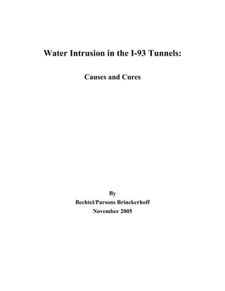
Project staff measure water inflow based on volumes handled every few days by tunnel pumps.
The figures are converted to a standard industry metric – number of gallons per minute per 1,000
linear feet of tunnel (gpm/1000LF).
The 2005 interim report by FHWA’s engineering panel cited an industry norm of 1 gpm/1000LF
in finished tunnels as an acceptable rate, below which standard maintenance programs can assure
the integrity of mechanical structures and electrical systems. That rate, it continued, “offers a
practical point of reference to evaluate how successful the project is in achieving the specified
requirement for a dry tunnel.”20
Even while still under construction, the I-93 tunnels easily beat that standard. Since the
beginning of April 2005, the average water flow pumped out of the tunnels has been only 0.5
gpm/1000LF (see Figure 1), a figure that includes rain carried in by vehicles and open portals.
18
In this respect, the observed performance of the slurry walls built for the BART system in 1968 are of
special significance, because of the similar nature of the structures (slurry walls with roof girder-pile
connections). Discussions with BART personnel indicate no corrosion issues involving the soldier piles,
and very limited corrosion issues in some wall areas exposed to seawater intrusion.
19
FHWA Tunnel Leak Assessment Team, FHWA Tunnel Leak Assessment: Boston Central Artery Interim
Report, March 23, 2005. The summary and full text of the interim report is available at
http://www.fhwa.dot.gov/reports/centralarterytunnel/tlabcainterim.pdf
20
FHWA Tunnel Leak Assessment Team, op. cit. European sources indicate even greater expected leakage
rates for large cut and cover tunnels of 1.5 to 3.5 gpm/1000LF.
-6-
8. The I-93 tunnels are becoming even drier over time as crews close them to weather (sealing
conduits and manhole covers, for example), repair defective wall panels, and grout roof joints.21
Since early July, volumes have averaged 0.3 gpm/1000LF—only a third of the industry norm—
despite several weeks of exceptionally heavy rainfall. The tunnels will be inspected again
following this winter and any new leaks that open will be grouted by the contractors as needed.
Figure 1
1.2
1.1
0.8
0.9
0.6
0.8
0.6
0.8
1.1
0.7
0.9
0.6
0.5
0.3
0.9
0.4
0.3
0.2
0.3
0.4
0.3
0.2 0.2
0.2
0.3
0.2
0.3
0.4
0.9
0.3
0.6
0.1
0.0
0.2
0.4
0.6
0.8
1.2
1.4
1.6
1.8
2.0
4/4
4/114/19
4/25
5/2
5/9
5/165/23
5/31
6/6
6/13
6/206/27
7/6
7/127/19
7/26
8/2
8/9
8/168/23
8/30
9/6
9/13
9/209/27
10/410/1010/1710/2410/31
11/7
GPM/1000LFOFTUNNEL
Water Flow
1.0
Trend Line
CENTRAL ARTERY TUNNEL PROJECT
I-93 LOW POINT PUMP VOLUMES
See CA/T LPPSVOLUM E file for data collection details/basis.
Data Points Rounded Off To One Decimal Place
Industry Norm for Completed Underground Tunnels1.0
NOTE: Adjusted data excludes volumes from the following water sources: ongoing
construction discharges, tunnel wash operations, panel hydroblasting / power washing, and
grouting operations.
WEEK
Weekly 3.3 .3 0 .9 .9 .7 .1 .6 2.6 .2 1.2 .2 .2 0 3.2 0 .2 0 1.1 1.1 0 0 1.0 0 1.1 0 .5 2.0 4.5 1.1 1.8 .2
Rainfall - in.
21
In addition, studies of other tunnels have shown a progressive reduction in seepage due to self-healing of
wall fissures due to calcification. The source of these mineral deposits is excess lime in the concrete, as
well as dissolved minerals in the groundwater. See Meuser Rutledge, Water Intrusion in Underground
Structures (Washington Metropolitan Area Transit Authority, USDOT, Final Report, October 1988).
-7-
9. Tunnel Maintenance
As the FHWA expert panel noted, and as MTA has acknowledged, all completed tunnels leak to
some extent. Even after the I-93 tunnels are complete and existing leaks are sealed, some new
seeps will almost certainly appear over time.22
They will be detected and sealed as part of a
normal maintenance program, which is expected to become fully operational in 2007. B/PB has
prepared an inspection manual and submitted it to the Massachusetts Turnpike Authority to
provide guidance. MTA will manage future tunnel maintenance, including routine grouting
beyond the contractors’ warranty period.23
Visual inspections in areas of the tunnels where water leakage has been most significant have
uncovered no significant corrosion issues. Where water damage has occurred, it is being repaired.
In general, the applied anti-corrosion coating systems are providing adequate protection to the
structural steel elements of the tunnel. There is no danger of joint failure assuming a proper level
of maintenance standard for this type of structure. With proper inspection and maintenance, including
continued attention to metal coatings, the tunnels should provide excellent service into the next
century.
Conclusion
The I-93 tunnels are built to ensure that Boston can meet its critical transportation needs for many
decades to come. They are already drier than most completed tunnels, and getting drier by
the week as the project heads toward substantial completion later this year. They represent an
enormous engineering and construction achievement of which the people of Massachusetts can be
proud.
22
On March 3, 2005, Associated Press quoted MTA spokeswoman Mariellen Burns as saying, “Our
agreement with the contractors is that they will deliver a dry tunnel. That doesn't mean watertight. It means
that there's always going to be leak maintenance. What level of that will be determined.”
23
Testimony of Matthew Amorello to House Government Reform Committee, April 22, 2005.
-8-