Analysis of Volatile Organic Compounds (VOCs) in Air Using US EPA Method TO-17
JEM diffusion tube paper
1. A new system of refillable and uniquely identifiable diffusion tubes for
dynamically generating VOC and SVOC standard atmospheres at ppm and
ppb concentrations for calibration of field and laboratory measurements
John M. Thompson* and David B. Perry
Received 29th January 2009, Accepted 9th June 2009
First published as an Advance Article on the web 22nd June 2009
DOI: 10.1039/b901954e
Calibration of trace analyses for volatile organic compounds (VOCs) and semivolatile organic
compounds (SVOCs) is an important but sometimes neglected aspect of environmental monitoring.
Static methods using mixtures of VOCs in compressed air or nitrogen suffer from uncertain adsorptive
losses on the gas cylinder wall and are not well suited for SVOCs. Dynamic methods enable generation
of standards when needed, using permeation or diffusion tubes in thermostatted ovens through which
a carrier gas flows whose flow-rate is user-controlled. We describe a new system of refillable diffusion
tubes engraved with individual serial numbers (for quality systems traceability) that users can easily
calibrate gravimetrically in a few weeks, compared with several months for gravimetric calibration of
permeation tubes. These devices may be useful for calibrating ppm and ppb measurements of VOCs and
SVOCs. Using appropriately low temperatures and an inert carrier gas, it may also be possible to
generate standards for many labile and oxygen sensitive compounds.
Introduction
The review by Barratt1
of static and dynamic methods of standard
gas mixture preparation is still relevant today. He highlighted the
disadvantages of static methods, especially for VOCs, that included
indeterminateadsorptivelossesonthegascylinderwalls,yetdespite
this, these methods are in common use today as the preferred cali-
bration method in many environmental monitoring programmes.
Dynamic generation of standard atmospheres avoids problems
of adsorptive losses encountered with static standards. This is
because a dynamic equilibrium is established between the vapour
being diluted by a carrier gas and the walls of the container in
which the vapour is mixed with that gas and on the walls of any
tubing used to transmit the standard mixture to the instrument
being calibrated. Such losses are only relevant and important
when a rapid change is made in the carrier gas flow rate, in which
case time must be allowed for a new equilibrium to be properly
established.
Vapour from the VOC in such dynamic methods has been
produced most commonly using a permeation tube, made from
a tube of a permeable thermoplastic polymer, such as PTFE, filled
with the VOC liquid and sealed at both ends. Permeation tubes are
incubated at a specified temperature (usually from 303K to 363K)
in a thermostatted oven through which a steady flow of a carrier
gas is passed and are calibrated gravimetrically. Emission
(permeation) rates of such tubes from commercial suppliers
typically range from 50 mg minÀ1
to as little as 5 ng minÀ1
, but an
emission rate of 5 ng minÀ1
would only result in a weight loss of 1
mg in 180 days. So, calibration becomes both very slow and
expensive. It cannot be relied upon for VOCs that may be labile
(e.g., styrene) nor for SVOCs with very low vapour pressures.
Barratt1
also referred to the use of diffusion tubes as suitable
sources of vapour and some relatively crude versions are avail-
able commercially that are made from a short length of capillary
tubing sealed at one end with a small glass bulb. The tube is filled
through the capillary so it is difficult to get complete drainage
into the bulb and the diffusion length is uncertain, so such tubes
are rarely used in practice.
Thompson et al.2
described a diffusion dilution cell in which
a precision capillary tube was encased in a thermostatted jacket
and vapour was allowed to evaporate from the VOC meniscus in
the capillary tube, diffusing from that into a mixing chamber
through which carrier gas flowed at a controlled rate. The VOC
diffusion path from the meniscus was defined by the length of the
tube from the meniscus to the exit and by its cross-sectional area.
If the VOC’s gas-phase diffusion coefficient and vapour pressure
were known at the cell’s operating temperature, the emission rate
in g sÀ1
could be calculated using an equation given by the authors.
More recently, Possanzini et al.3
described a simple refillable
diffusion tube design which they evaluated with a series of semi-
volatile n-alkanals. Komenda et al.4,5
used a diffusion source for
generating standards of labile compounds: isoprene, methyl vinyl
ketone, methacrolein and various terpenes.
With permeation tubes, one can make standard atmospheres
containing several components by putting several different tubes
together in a thermostatted oven of a vapour standards generator.
Ideally, it would be useful if we could do the same with diffusion
tubesbutabetter,moreadaptable designofsuchdevicesis needed.
The new design of diffusion tube
We approached the design problem by considering an easily
refillable and versatile class of diffusion tubes, adopting the
Tracer Measurement Systems Ltd., Unit 107, Institute of Research and
Development, Birmingham Research Park, Vincent Drive, Edgbaston,
Birmingham, B15 2SQ, UK. E-mail: jmtdoc@btinternet.com; Tel: +44
(0)7787 552913
This journal is ª The Royal Society of Chemistry 2009 J. Environ. Monit., 2009, 11, 1543–1544 | 1543
TECHNICAL NOTE www.rsc.org/jem | Journal of Environmental Monitoring
2. principles of the diffusion dilution cell, i.e., to have a well-defined
diffusion pathway of known length and cross-sectional area
through which vapour could exit the tube. That was achieved
(ª 2008, Tracer Measurement Systems Ltd.) using a piece of
precision bore glass tubing of well-defined length sealed into
a glass reservoir which is connected to another reservoir with
a screw thread attached (see Fig. 1). This can be sealed tightly
with a screw cap with a septum covered with nickel or gold foil to
prevent leakage of the reservoir contents. The device can easily be
filled with an SVOC or a VOC via the screw-threaded end. The
diffusion tube is thermostatted in a horizontal position and the
bore of the precision bore tube is never allowed to be wetted by
the VOC or SVOC, so the diffusion path is precisely measurable
by the user with a Vernier microscope. In addition, each tube is
permanently engraved with a unique serial number for trace-
ability in a quality management system. Tubes with emission
rates of 0.05 to 1 mg minÀ1
can easily be calibrated gravimetrically
in a few weeks with a standard laboratory balance weighing to
0.1 mg.
We have developed a system of diffusion tube devices in which
precision bore tube lengths range from 2 to 10 cm and have
a bore diameter from 4 mm to 0.1 mm, giving an emission rate
range of about 8000 fold at any given oven temperature in the
vapour standards generator. By varying the temperature of the
thermostatted oven of the standards generator, that range may
be extended considerably. Calibrating with a tube of moderate
emission rate, one can then calculate emission rates for other
devices in this system using a scaling factor related to tube
lengths and bore cross-sectional areas, so it is possible to create
ppm and ppb concentration standards in a straightforward way.
Users can also calibrate an analytical method whilst it is being
developed, even for substances that it may not normally be
possible or reliable to do so with permeation tubes, e.g., labile
materials (e.g., styrene) or oxygen-sensitive substances
(e.g., phenols or aldehydes) by using oxygen-free nitrogen carrier
gas in the standards generator. It may be possible to use SVOCs
and also solids that sublime to produce vapour with the wider
bore tube devices, even for validating field measurements using
portable vapour standards generators.
When using these devices, it is important to recognise that
after they have been first placed in the thermostatted oven, they
will take some time to come to thermal equilibrium. Thus, even
though the screw is tightened to a secure seal initially, it will
become loose as the cap, septa and screw thread equilibrate to the
oven temperature. The cap will need tightening several times
during the initial equilibration period of a week or two, in order
that a steady emission rate is achieved.
Such care in use would also be required with the diffusion tube
described by Possanzini et al.,3
although they do not explicitly
state such a requirement. Their device also requires a good seal
between the capillary tube, the PTFE coated silicone rubber
gasket (home-made from septa commonly used in GC) and the
polythene screw cap. This approach to achieving a seal may be
potentially a serious problem.
Experimental results
In our initial laboratory trials, we have evaluated the emission
rates with these devices for benzene and toluene as examples.
Diffusion tubes were incubated at 40.1
C in a Span Chek
portable vapour standards generator (Kin Tek Inc., USA) and
they were weighed at regular intervals over a period of three
weeks using a standard laboratory balance weighing to 0.1 mg.
The diffusion tubes used in each case had the precision bore
tubing of 0.2 mm bore and 2 cm length. The emission rates for
benzene and toluene under these conditions were found to be,
respectively, about 8.76 and 5.31 ng sÀ1
(or 526 and 319 ng
minÀ1
). Thus, if these emissions were fed into a carrier gas flowing
at 1 l minÀ1
, we could dynamically generate standards for these
vapours of concentrations 6.73 and 3.46 nM, respectively.
Varying the volumetric flow rate of the carrier gas (and allowing
for stabilisation of the new dilutions) would enable rapid
production of a useful range of concentrations for the
construction of a calibration curve.
Acknowledgements
The authors gratefully acknowledge support from Advantage
West Midlands through their Technology Transfer Fund
(Project number 2229-07).
References
1 R. S. Barratt, Analyst, 1981, 106, 817.
2 J. M. Thompson, R. L. Jones and R. S. Barratt, Br. J. Anaesth., 1975,
47, 1177–1184.
3 M. Possanzini, V. Di Palo, E. Brancaleoni, M. Frattonni and
P. Ciccioli, J. Chromatogr., A, 2000, 883, 171–183.
4 M. Komenda, E. Parusel, A. Wedel and R. Koopman, Atmos.
Environ., 2001, 35, 2069–2080.
5 M. Komenda, A. Schaub and R. Koopman, J. Chromatogr., A, 2003,
995, 185–201.
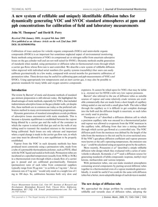
Fig. 1 Tracer Diffusion Tubes with a bore diameter of 1 mm and 0.2 mm
and precision bore tube lengths of 2 and 10 cm, respectively.
1544 | J. Environ. Monit., 2009, 11, 1543–1544 This journal is ª The Royal Society of Chemistry 2009