John Pederson has taken up celestial navigation as a hobby. He constructs homemade instruments from household items to measure angles of celestial objects and determine his location through latitude and longitude. Some of the instruments he creates include a quadrant made from a straw and string to measure vertical angles, and a sextant made from Legos and a CD case that uses mirrors to measure angles between objects. His goal is to learn navigation techniques used by various cultures and to pinpoint his location through homemade instruments, as was done before modern navigation technology.
1. John
Pederson
Homemade
Celestial
Navigation
General
Overview:
For
the
past
several
years,
as
a
research-‐based
hobby,
I’ve
set
out
to
learn
and
practice
the
“lost
art”
of
celestial
navigation.
In
the
past,
navigators
would
measure
the
angular
heights
of
the
sun
and
stars,
using
the
information
to
plot
their
position
on
the
globe
(in
degrees
of
latitude
and
longitude).
With
instruments
I
made
from
household
materials,
I’ve
sought
to
pinpoint
my
location
in
the
same
way,
drawing
on
techniques
from
various
cultures
around
the
world.
The
Polynesian
seafarers,
whom
I
researched
as
a
history
project,
used
their
knowledge
of
star
positions
to
navigate
and
colonize
a
third
of
the
Earth’s
surface
without
any
instruments.
Arab
traders
used
simple
ones
to
tell
their
latitude
in
the
featureless
Arabian
Desert.
European
and
American
navigators,
up
until
World
War
II,
used
highly
accurate
sextants
to
locate
themselves
to
within
a
mile.
I’ve
researched
all
of
their
techniques
to
help
me
do
the
same.
As
a
further
challenge,
American
explorers
used
such
instruments
to
determine
the
local
time;
this
compensated
for
their
inaccurate
timepieces.
I
researched
and
performed
this
task
as
well;
the
technique
uses
the
same
navigation
concepts.
Constructing
the
Instruments:
Building
instruments
at
home
of
the
same
caliber
as
those
of
professional
craftsmen
is
impossible,
so
I
used
various
tricks
to
overcome
the
limitations
of
household
items.
Below
is
one
of
the
first
instruments
I
created,
a
quadrant.
It
can
measure
the
vertical
angle
of
an
object
above
the
horizon
by
using
a
plumb
bob.
When
one
tilts
the
quadrant
a
certain
number
of
degrees
upward,
its
plumb
bob
points
to
the
equivalent
number
of
degrees
on
the
scale.
In
usage,
I
sight
through
the
tube
on
top,
let
the
string
swing
downward
and
settle,
pinch
the
string
to
its
place
on
the
scale,
and
read
the
angle.
I
fitted
the
sighting
tube,
a
straw,
with
a
pinhole
sight,
allowing
focus
on
both
faraway
and
nearby
objects
simultaneously.
(It’s
similar
to
the
pinhole
camera
used
to
produce
the
famous
James
Bond
gun
barrel
sequence,
where
the
target
and
the
gun
barrel’s
rifling
are
both
in
focus.)
Below
is
picture
of
the
instrument,
plus
one
showing
me
sighting
the
top
of
a
tree.
2.
3. The
second
instrument
I
made
is
a
sextant,
an
instrument
that
relies
on
the
positioning
of
two
mirrors
to
optically
determine
angles
between
objects.
One
looks
into
the
device,
swings
the
arm
(or
in
my
case,
rotates
the
CD
mirror)
until
the
two
objects’
images
appear
superimposed,
and
reads
the
angle
on
the
scale.
Because
the
instrument
requires
a
high
degree
of
dimensional
precision,
I
used
Legos
to
provide
precise
right
angles.
The
perpendicular
pivot
point
is
also
difficult
to
replicate,
so
I
used
a
CD
case.
(Everything
that
reflects
light
on
the
sextant
must
be
perpendicular
to
the
base,
for
not
doing
so
causes
the
images
one
sees
to
be
misaligned;
this
affects
the
angle
measured.)
The
tiny
arc
(only
about
6
cm
in
radius)
is
impossible
to
read
past
integer
degrees,
so
I
drew
and
printed
a
vernier
scale
to
theoretically
achieve
minute
accuracy.
(1
degree
=
60
minutes
of
arc.)
In
practice,
I
could
only
read
the
scale
to
around
15
arc
minutes,
for
extreme
precision
is
needed
to
match
the
arc
of
the
vernier
exactly
with
the
arc
of
the
sextant
arm.
The
mirror
edges
are
rough,
for
they
are
cut-‐up
makeup
mirrors.
I
removed
half
of
the
silvering
from
the
mirror
on
the
CD
case
–
this
allows
me
to
see
both
sighted
objects
at
the
same
time,
one
in
each
half
of
the
mirror.
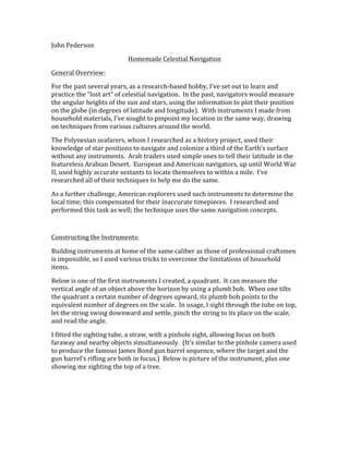
4.
The
above
image
shows
the
sextant
in
operation;
I’m
measuring
the
angle
between
my
desk
lamp
and
my
globe.
The
central
mirror
on
the
CD
itself
(its
edge
is
just
visible
on
the
right)
rotates
with
the
CD,
allowing
the
angle
it
makes
with
the
mirror
on
the
CD
case
(very
center
of
picture)
to
be
easily
adjusted.
The
light
coming
from
the
lamp
(just
outside
the
picture,
to
the
right)
is
reflecting
off
the
central
mirror
on
the
CD,
reflecting
again
off
the
mirror
on
the
CD
case,
and
reaching
the
camera
as
an
image
of
the
lamp
(visible
in
the
CD
case
mirror).
In
this
picture,
the
lamp
appears
to
be
visually
lined
up
with
the
edge
of
the
globe.
By
reading
the
angle
that
the
central
mirror
was
rotated,
I
can
determine
the
angle
between
the
two
objects.
The
third
instrument
I
made
is
an
artificial
horizon.
In
the
suburbs
of
Houston,
I
cannot
see
the
horizon
–
there
are
way
too
many
trees
and
buildings
in
the
way.
A
sextant,
without
a
plumb
line,
needs
an
external
reference
to
measure
angles.
North
American
and
Antarctic
explorers
solved
this
problem:
by
using
a
pan
of
mercury
covered
with
a
windscreen,
they
would
sight
the
angle
between
a
star
and
its
reflected
image
in
the
tray.
This
measurement
was
double
the
angle
between
the
star
and
the
invisible
horizon.
For
obvious
reasons,
I
didn’t
want
to
handle
mercury,
so
I
used
plain
water
in
my
horizon.
The
windscreen
needs
to
have
perpendicular
glass
panes
(to
avoid
refraction
error),
so
I
used
Legos
again
to
get
sufficient
ninety-‐degree
accuracy.
5. Also,
the
water’s
surface
needs
to
be
completely
shielded
from
wind,
so
pardon
the
unattractive
masking
tape
–
it’s
making
an
airtight
seal.
Below
is
a
photo
of
the
reflected
image
it
produces.
6.
You
can
see
both
a
flashlight
and
its
reflected
image
in
this
picture
of
the
artificial
horizon
(the
triple
dots
in
the
clear
plastic
dish).
If
the
flashlight
were
as
far
away
as
the
stars,
the
bisector
of
the
angle
between
the
images
would
be
the
true
horizon.
Calculator
Programming:
The
theory
behind
celestial
navigation
involves
a
lot
of
spherical
geometry
and
trigonometric
ratios,
for
one
is
calculating
angles
and
distances
on
triangles
that
span
the
globe.
In
the
past,
navigators
used
precomputed
tables
to
“reduce”
their
sights;
nowadays,
a
scientific
calculator
can
do
the
calculations
directly.
I
learned
calculator
programming
from
a
friend
of
mine,
so
I
wrote
the
requisite
formulas
into
7. a
program
that
prompts
you
for
values,
performs
the
calculations,
and
returns
the
information
I
need
to
plot
my
position
on
a
chart.
The
method
of
sight
reduction
I
use
to
turn
measured
celestial
angles
into
chart
positions
is
called
the
“azimuth
intercept
method”.
The
method
uses
the
sighted
angle
and
the
time
of
observation
to
produce
a
“line
of
position”,
or
a
line
across
the
Earth’s
surface
that
passes
through
where
I
am.
To
find
my
position
on
this
line,
I
need
at
least
two
lines
of
position
to
intersect.
I
created
a
second
program
to
plot
the
lines
on
the
calculator’s
graph
itself.
This
makes
it
easy
for
me
to
find
my
location
–
I
simply
use
the
<Intercept>
function
to
find
where
the
lines
meet.
Below
is
a
real
intersection,
or
fix
of
my
location,
from
two
sextant
sights
that
I
did.
Another
technique
of
sight
reduction,
based
on
the
same
principles,
allows
one
to
sight
the
sun
and
calculate
the
local
time
that
the
sight
was
taken
–
without
the
use
of
a
watch.
This
trick
was
useful
to
American
explorers
with
inaccurate
timepieces.
I
took
the
time
sights
with
the
quadrant,
because
using
the
sextant
would
have
required
dark
solar
shades
(to
protect
my
eyes
from
the
sun’s
image).
I
didn’t
look
directly
at
the
sun;
I
used
the
sighting
tube’s
shadow
to
reverse-‐sight
the
sun’s
altitude.
By
this,
I
mean
that
I
aligned
the
sighting
tube
backwards;
when
I
could
see
the
light
from
the
pinhole
sight’s
hole
in
the
shadow,
it
meant
that
the
tube
was
8. perfectly
aligned
with
the
sun’s
rays.
(In
the
picture
below,
you
can
see
the
hole’s
speck
of
light
on
my
thigh,
in
the
middle
of
the
tube’s
shadow.)
I
then
read
the
angle.
I
programmed
the
necessary
trigonometry
for
the
method
into
a
third
program;
it
uses
the
sight
taken,
your
latitude,
and
the
declination
of
the
sun
on
that
day
to
provide
the
local
time.
Because
this
“local
apparent
time”
is
not
CST,
I
needed
to
add
several
corrections
to
check
my
accuracy.
Below
is
a
picture
of
a
sample
calculation
page
–
it
shows
the
various
corrections
I
make
for
each
time
sight
that
I
do.
I
start
by
recording
the
sun’s
angular
height
and
the
exact
time
I
took
the
sight.
(Recording
the
time
is
purely
to
determine
my
error
–
if
I
were
actually
trying
to
figure
out
the
local
time
from
scratch,
I
would
obviously
not
have
access
to
a
watch!)
I
then
record
the
day’s
mean
values
of
the
sun’s
declination
and
the
equation
of
time.
(These
values
are
defined
below.)
Using
my
third
program,
I
calculate
the
local
apparent
time
based
on
my
approximate
latitude,
the
sun’s
declination,
and
the
recorded
height
of
the
sun.
To
this
time
(2:57:22
in
the
example)
I
add
the
equation
of
time
value
for
that
day
(+00:05:11)
to
get
the
local
mean
time.
If
I
didn’t
have
a
watch
and
were
truly
lost,
I
would
stop
here;
however,
I’m
in
a
city
full
of
clocks
and
appointments,
so
I
do
some
more
corrections
to
convert
that
time
into
CST.
By
adding
the
correction
for
daylight
savings
time
(+1:00:00)
and
compensating
for
my
longitude
west
of
the
CST
zone
line
9. (+00:21:58),
I
get
the
time
of
my
sight
in
CST,
which
I
then
compare
to
my
watch
recording
to
get
an
error.
Without
a
nautical
almanac
on
hand,
the
sun’s
declination
and
equation
of
time
value
are
difficult
to
know
precisely.
(The
sun’s
declination
is
how
far
north
or
south
of
the
equator
the
sun
appears
to
be
on
a
certain
day
of
the
year;
the
equation
of
time
is
a
correction
for
the
Earth’s
elliptical
orbit
and
its
tilt,
both
of
which
affect
the
sun’s
position
in
the
sky.)
To
address
this,
I
wrote
a
fourth
program;
it
uses
trigonometric
equations
to
approximate
these
two
effects,
thus
calculating
the
two
values
for
any
day
I
wish.
Below
the
sample
time
calculation
is
a
screenshot
of
my
declination/equation
of
time
value
calculation
program.
10.
Conclusions:
Through
research,
careful
instrument
construction,
and
programming,
I
am
able
to
practice
celestial
navigation
with
respectable
accuracy
(by
pre-‐GPS
standards,
at
least).
I
can
sight
the
altitude
of
stars
to
within
a
fourth
of
a
degree,
using
my
homemade
sextant
and
artificial
horizon.
For
less
precision,
I
can
use
my
quadrant
to
measure
angles
to
within
a
degree.
Both
instruments
are
made
from
household
materials,
too.
With
the
sights,
I
can
use
my
own
calculator
programs
to
plot
lines
of
position
and
achieve
location
fixes.
I
have
actually
located
myself
to
within
a
tenth
of
a
degree
of
latitude
and
longitude!
I
can
find
the
local
time
and
CST
using
only
a
quadrant
and
a
graphing
calculator.
My
average
error,
decreasing
with
experience,
is
2
minutes
20
seconds.
That’s
about
as
accurate
as
most
people’s
watches!
I
now
have
a
profound
appreciation
for
the
navigators
of
the
cultures
mentioned,
made
stronger
with
every
measurement
I’ve
taken
over
the
past
three
years.
This
pursuit
has
been
truly
intellectually
fulfilling;
I
never
dreamed
it
would
take
me
this
far,
so
I
can’t
wait
to
see
where
it
will
take
me
next.
11. References
I’ve
Used:
http://www.samlow.com/sail-‐nav/starnavigation.htm
This
site
teaches
some
basic
theory
behind
celestial
navigation,
specifically
how
the
stars
appear
to
move
as
one’s
location
changes.
Discusses
other
Polynesian
techniques.
http://www.northwestjournal.ca/dtnav.html
This
magazine
article
discusses
the
reconstructed
and
reanalyzed
techniques
of
the
North
American
explorer
David
Thompson.
Provides
several
worked-‐out
and
explained
examples
of
various
sextant
and
navigational
procedures.
This
is
where
I
sourced
the
formulas
for
local
time
sights.
http://straitofmagellan.blogspot.com/search/label/Celestial%20Navigation%2010
1
This
is
a
collection
of
blog
articles
outlining
the
basics
behind
the
azimuth
intercept
method,
as
instructed
by
a
USCG
licensed
captain.