The document describes several projects completed by Jack Joyce involving design and modeling using SolidWorks. For the first project, Jack designed the brushless DC motor sub-assembly and propeller for a quadcopter modeled after a yellow jacket. For another project, Jack designed a Blackhawk helicopter in SolidWorks that was 3D printed. Jack also participated in undergraduate UAV research where he helped construct a quadcopter and worked with an Arduino and stepper motors. Additionally, Jack's group designed and built a balsa wood glider to analyze flight characteristics.
1. Buzzcopter
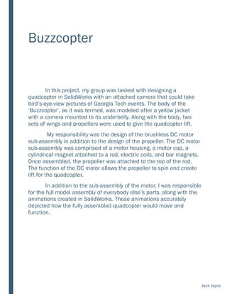
In this project, my group was tasked with designing a
quadcopter in SolidWorks with an attached camera that could take
bird’s-eye-view pictures of Georgia Tech events. The body of the
‘Buzzcopter’, as it was termed, was modeled after a yellow jacket
with a camera mounted to its underbelly. Along with the body, two
sets of wings and propellers were used to give the quadcopter lift.
My responsibility was the design of the brushless DC motor
sub-assembly in addition to the design of the propeller. The DC motor
sub-assembly was comprised of a motor housing, a motor cap, a
cylindrical magnet attached to a rod, electric coils, and bar magnets.
Once assembled, the propeller was attached to the top of the rod.
The function of the DC motor allows the propeller to spin and create
lift for the quadcopter.
In addition to the sub-assembly of the motor, I was responsible
for the full model assembly of everybody else’s parts, along with the
animations created in SolidWorks. These animations accurately
depicted how the fully assembled quadcopter would move and
function.
Jack Joyce
2. Motor assembly
Exploded view of motor & bill of assembly
SolidWorks full assembly of Buzzcopter layered onto a background
Jack Joyce
3. 3D print of UH-60 Blackhawk
For an individual manufacturing
design project, I designed a Blackhawk
helicopter in SolidWorks. Using 2D
projections of the top and side of my
drawings, I was then able to use
multiple cross-sectional lofts to create
the base of the helicopter. On top of the
helicopter I created an angular snap-fit
using hole and shaft tolerancing data
that allowed the rotor to attach and
spin on top of the base. The project
was chosen by my professor to be 3D-
printed to showcase successful design
and tolerancing practices.
SolidWorks assembly of the base and propeller
3D printed base and propeller parts
Jack Joyce
4. Undergraduate UAV Research
Under Dr. Sylvester Ashok, the project leader of the Integrated
Product Lifecycle Engineering Laboratory, I completed a semester of
UAV research in the fall of 2015. My primary focus as a research
assistant was in constructing the body of the UAV, as well as wiring
the brushless DC motors to the KK2 control board. This valuable
learning experience showed me a real-life application of aerospace
engineering.
In addition to working with the quadcopter, we were tasked
with using an ArduinoUNO and stepper motors to control a hot-wire
that could be used to cut airfoils. The project was based off of a
thesis investigated by a graduate student at MIT, in which PCB’s were
used to move the stepper motors instead of an ArduinoUNO.
Programming the Arduino to control stepper motors gave me valuable
insight into the world of Arduino programming.
The quadcopter I
constructed along with
the RC remote that was
synced with the KK2
control board
Jack Joyce
5. Design-Build-Fly
■ In order to investigate real-life flight-worthiness
standards, our group built a balsa-wood glider
to analyze the coefficients of lift and drag,
along with the aircraft’s static margins. We were
given limits and target number ranges for these
values, so that we could experience the design
characteristics a design engineer would have to
stick to in the real world. The glider’s wings
were cut using an Xacto knife and glued on to
the fuselage (a long, slender, square rod of
balsa-wood); the vertical and horizontal
stabilizers were constructed using the same
method. In order to analyze and perform
calculations of our design, we were provided
with a design tool that allowed us to calculate
coefficients of lift, drag, static margins, center
of gravity, span efficiency factor, mean
aerodynamic chord, and other performance
values.
2D drawings of the final design
Jack Joyce