Stahl 6521_4 Floodlight - ATEX Zone 1 Zone 2 Hazardous Area Lighting
US8113683_Thermal_Isolation
1. (12) United States Patent
Ehresman et a1.
US008113683B1
US 8,113,683 B1
Feb. 14, 2012
(10) Patent N0.:
(45) Date of Patent:
(54)
(75)
(73)
(21)
(22)
(51)
(52)
(58)
(56)
HID LUMINAIRE WITH THERMALLY
ISOLATED LAMP AND BALLAST
COMPARTMENTS
Inventors: Adrian Thomas Ehresman, Aurora, CO
(US); Jeffrey Brian Nepple, Evergreen,
CO (US)
Assignee: Cooper Technologies Company,
Houston, TX (US)
Notice: Subject to any disclaimer, the term ofthis
patent is extended or adjusted under 35
U.S.C. 154(b) by 92 days.
Appl. N0.: 12/777,651
Filed: May 11, 2010
Int. Cl.
F21S 8/06 (2006.01)
US. Cl. ................. .. 362/218; 362/221; 362/217.02;
362/260; 362/263; 362/265
Field of Classi?cation Search ................ .. 362/218,
362/221, 217.02, 260, 261, 263*265
See application ?le for complete search history.
References Cited
U.S. PATENT DOCUMENTS
4,268,894 A * 5/1981 Bartuneket a1. ............ .. 362/158
5,597,233 A 1/1997 Lau
6,565,234 B1 5/2003 Skegin et a1.
7,430,120 B2 9/2008 Lau
7,506,994 B1 3/2009 Waycaster et a1.
7,513,646 B2 4/2009 Catone et a1.
7,597,458 B2 * 10/2009 Johnson et a1. ............. .. 362/265
7,604,366 B1* 10/2009 Chen . . . . . . . . . . . . . . . . . .. 362/99
7,621,656 B2* 11/2009 Tyson . 362/260
7,775,676 B2* 8/2010 Yang ........................... .. 362/221
2010/0002452 A1 1/2010 Gananathan
* cited by examiner
Primary Examiner * Anabel Ton
(74) Attorney, Agent, or Firm * King & Spalding LLP
(57) ABSTRACT
An HID luminaire includes a single luminaire housing that
includes thermally isolated lamp and ballast compartments.
At least one HID lamp is disposed Within the luminaire hous
ing, and at least one ballast is disposed Within the ballast
compartment. The lamp and ballast compartments are sepa
rated by a chamber that includes a substantially nonconduc
tive member, Which prevents heat from the lamp compart
ment from travelling to the ballast compartment. Thermally
isolating the ballast from at least a portion ofthe heat gener
ated by the HID lamp alloWs the ballast to be disposed rela
tively close to the HID lamp Without becoming overheated
and damaged. A holloW, threaded rod extends betWeen and
couples together the lamp compartment and ballast compart
ment. Electric Wires connecting the HID lamp and ballast
extends through the threaded rod, providing necessary elec
trical poWer in an aesthetically pleasing design.
20 Claims, 3 Drawing Sheets
5. US 8,113,683 B1
1
HID LUMINAIRE WITH THERMALLY
ISOLATED LAMP AND BALLAST
COMPARTMENTS
TECHNICAL FIELD
The present disclosure relates generally to light ?xtures,
and more speci?cally to an HID luminaire that includes ther
mally isolated lamp and ballast compartments.
BACKGROUND
A luminaire is a system for producing, controlling, and/or
distributing light for illumination. For example, a luminaire
can include a system that outputs or distributes light into an
environment, thereby alloWing certain items in that environ
ment to be visible. Luminaires are often referred to as “light
?xtures.”
An HID luminaire includes at least one high intensity dis
charge (“HID”) lamp. The HID lamp is connected to at least
one ballast that controls the current ?oWing through the HID
lamp. By controlling the current ?oW, the ballast can be used
to control the brightness of the HID lamp.
As a byproduct of converting electricity into light, an HID
lamp typically generates a substantial amount of heat. If
alloWed to accumulate, the heat generated by the HID lamp
can cause damage to the ballast. For example, raising the
operating temperature of the ballast can result in e?iciency
degradation and premature failure of the ballast, thereby
decreasing the lifespan and functionality of the HID lumi
naire.
Traditionally, HID luminaire manufacturers have
addressedthis problembyplacingthe HID lamp andballast in
different housings that are located far apart from one another.
This con?guration is expensive at least because a substantial
amount of Wiring is required to electrically connect the HID
lamp housing With the ballast housing and because installa
tion and maintenance ofthe HID luminaire requires a person
to access and manipulate tWo different housings. This con
?guration also is generally undesirable because the external
Wiring and connections betWeen the remote housings are not
aesthetically pleasing.
SUMMARY
The invention provides a luminaire, Which includes a cost
effective, aesthetically pleasing con?guration that prevents
heat output from the lamp from damaging a ballast of the
luminaire. In particular, the invention provides a luminaire,
Which can include, in one device that looks like a single
luminaire housing, thermally isolated lamp and ballast com
partments. At least one lamp can be disposed Within the
luminaire housing, and at least one ballast can be disposed
Within the ballast compartment. The lamp and ballast com
partments can be separated by a chamber that includes a
substantially nonconductive member, Which can prevent heat
from the lamp compartment from travelling to the ballast
compartment. This con?guration thermally isolates the bal
last from at least a portion ofthe heat generated by the lamp,
alloWing theballastto be disposedrelatively close to the lamp
Without becoming overheated. Although the luminaire is gen
erally described herein as an HID luminaire, a person of
ordinary skill in the art having the bene?t of the present
disclosure Will recogniZe that the luminaire can include any
type oflamp, such as a ?uorescent, compact ?uorescent, light
emitting diode (LED), or incandescent lamp.
20
25
30
35
40
45
50
55
60
65
2
In one aspect, the luminaire can include a lamp housing
that includes a ?rst elongated member con?gured to house a
lamp. The ?rst elongated member can include opposing ?rst
and second ends. The ?rst end ofthe ?rst elongated member
can de?ne an opening through Which light from the lamp is
emitted. The second end of the ?rst elongated member can
include a ?rst removable cap to Which a socket is mounted.
The socket is con?gured to receive the lamp. For example, a
person can remove the cap to install, replace, remove,
manipulate, or otherWise access the lamp.
The luminaire also includes a ballast compartment, Which
can include a second elongated member that is con?gured to
house a ballast, Which is con?gured to control the lamp. The
second elongated member can include opposing ?rst and
second ends. The ?rst end ofthe ?rst elongated member and
the second end of the second elongated member can de?ne
opposite ends ofthe luminaire. The second end ofthe second
elongated member can comprise a second removable cap,
Which is positionable by a person to install, replace, remove,
manipulate, or otherWise access the ballast.
A substantially nonconductive member can be disposed
substantially betWeen the lamp compartment and the ballast
compartment. The substantially nonconductive member can
engage the second end of the ?rst elongated member and the
?rst end of the second elongated member. Because it is sub
stantially nonconductive, the substantially nonconductive
member can prevent heat from the lamp from travelling from
the ?rst elongated member to the second elongated member.
A substantially holloW member can extend through the
substantially nonconductive member, the second end of the
?rst elongated member, and the ?rst end of the second elon
gated member, thereby coupling together the ?rst elongated
member, the substantially nonconductive member, and the
second elongated member. The substantially holloW member
alone can couple these components together. Alternatively, a
combination of the substantially holloW member and other
components of the luminaire can couple together the ?rst
elongated member, the substantially nonconductive member,
and the second elongated member. The substantially holloW
member can be con?gured to house at least a portion of at
least one electric Wire, Which electrically couples the lamp to
the ballast.
These and other aspects, features, and embodiments ofthe
inventionWill become apparent to a person ofordinary skill in
the art upon consideration of the folloWing detailed descrip
tion of illustrated embodiments exemplifying the best mode
for carrying out the invention as presently perceived.
BRIEF DESCRIPTION OF THE DRAWINGS
For a more complete understanding of the present inven
tion and the advantages thereof, reference is noW made to the
folloWing description, in conjunction With the accompanying
?gures brie?y described as folloWs.
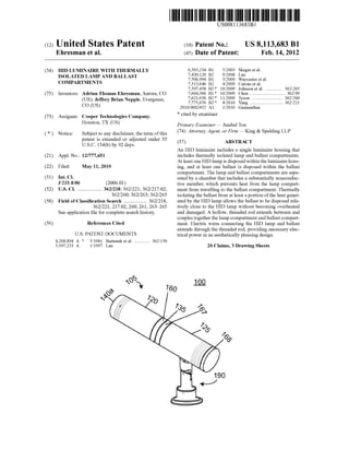
FIG. 1 is an isometric vieW an HID luminaire, in accor
dance With certain exemplary embodiments.
FIG. 2 is an exploded vieW ofthe HID luminaire ofFIG. 1,
in accordance With certain exemplary embodiments.
FIG. 3 is a cross-sectional vieW of the HID luminaire of
FIG. 1, in accordance With certain exemplary embodiments.
DETAILED DESCRIPTION OF EXEMPLARY
EMBODIMENTS
The folloWing description of exemplary embodiments
refers to the attached draWings, in Which like numerals indi
cate like elements throughout the several ?gures.
6. US 8,113,683 B1
3
FIGS. 1-3 illustrate an HID luminaire 100 in accordance
With certain exemplary embodiments. The HID luminaire
100 includes a single luminaire housing 105, Which contains
both an HID lamp 110 and a ballast 115 that controls the HID
lamp 110. More speci?cally, the luminaire housing 105
includes a lamp compartment 120 that houses the HID lamp
110 and a ballast compartment 125 that houses the ballast
115. The lamp compartment 120 and ballast compartment
125 are separated by a chamber 130 that includes a substan
tially nonconductive member 135, Which prevents heat from
the lamp compartment 120 from travelling to and damaging
the ballast 115, as described beloW.
As best seen in FIG. 2, the exemplary lamp compartment
120 includes a substantially cylindrical housing 140 having
opposing ends 14011 and 14011 that include openings 1401111
and 1401111, respectively. The housing 140 includes a member
141 that de?nes a channel 1400 that connects the openings
1401111 and 140ba. The HID lamp 110 is disposed Within the
channel 1400. Light generated by the HID lamp 110 is output
through the opening 1401111. While the exemplary embodi
ment describes the housing 140 as being cylindrical, other
geometric and non-geometric shapes including, but not lim
ited to, square and rectangular are contemplated and Within
the scope and spirit of this disclosure.
The HID lamp 110 is a lamp that generates light using an
electric arc or “discharge” betWeen tWo electrodes (not
shoWn) in the lamp 110. When the HID lamp 110 is installed
in the HID luminaire 100, the electrodes are components ofan
electrical circuit, Which includes the ballast 115. When the
ballast 115 energiZes the electrical circuit, an electric arc
forms betWeen the electrodes and ioniZes gas and metallic
vapor, such as mercury, metal halide, or high-pressure
sodium, Within the HID lamp 110. This ioniZation causes an
electric arc to strike betWeen the tWo electrodes. That arc
radiates intense light. Although an HID lamp 110 can be used
in substantially any lighting application, its intense light out
put makes it particularly suited for outdoor lightning appli
cations and large indoor arena environments. For example,
the luminaire 100 may include any of a variety of structures
190 for mounting the luminaire to a Wall or other surface in
the environment, as Would be readily understood by a person
of ordinary skill in the art having the bene?t of the present
disclosure.
In certain exemplary embodiments, the luminaire 100
includes a re?ector 165 and/or a cover 170 disposed in the
housing 140, substantially betWeenthe HID lamp 110 and the
opening 1401111. The exemplary re?ector 165 depicted in
FIGS. 1-3 includes a substantially frusto-conical shaped
member comprised of a material that re?ects, refracts, trans
mits, or diffuses light emitted by the HID lamp 110. The
exemplary cover 170 depicted in FIGS. 1-3 includes a sub
stantially cylindrical, opticallytransmissive memberthatpro
vides protection to the HID lamp 170 from dirt, dust, mois
ture, and any other environmental contaminants. In certain
exemplary embodiments, the cover 170 is con?gured to con
trol light from the HID lamp 110 via refraction, diffusion,
baf?es, louvers, or the like. For example, the cover 170 is
capable of including a refractor, a lens, an optic, or a milky
plastic or glass element.
A person ofordinary skill in the art having the bene?t ofthe
present disclosure Will recogniZe that the shape and material
ofthe re?ector 165 and the cover 170 can vary depending on
a variety of factors, including the siZe and shape of the HID
lamp 110, the siZe and shape of the opening 1401111, the siZe
and shape ofthe housing 105 or the individual compartments
120, 125, andthe desiredphotometric distribution ofthe light.
Depending on the desired lighting application, the luminaire
20
25
30
35
40
45
50
55
60
65
4
100 may not include a re?ector 165 or a cover 170 in certain
alternative exemplary embodiments.
The HID lamp 110 is electrically coupled to a socket 145,
Which is in turn electrically coupled to the ballast 115. The
socket 145 is mounted Within the housing 140 via a bracket
155 coupled to a cap 160, Which is removably coupled to the
end 1401) of the housing 140. In the exemplary embodiment
depicted in FIGS. 1-3, the cap 160 is removably coupled to the
end 1401) ofthe housing 140 via interlocking threads 16011 on
or in the cap 160 and end 140b, and the bracket 155 is coupled
to the cap 160 via one or more screWs 15511. A person of
ordinary skill in the art having the bene?t of the present
disclosure Will recogniZe that any other fastening means, such
as one or more screWs, nails, snaps, clips, collars, and/or pins,
may be used to removably couple the cap 160 to the end 1401)
and/or to couple the bracket 155 to the cap 160 in certain
alternative exemplary embodiments.
The ballast 115 is disposed Within the ballast compartment
125. The ballast compartment 125 includes a substantially
cylindrical housing 163 having opposing ends 16311 and 16311
that include openings 1631111 and 163ba, respectively. While
the exemplary embodiment describes the ballast compart
ment 125 as being cylindrical, other geometric and non-geo
metric shapes, including, but not limited to, square and rect
angular are contemplated and Within the scope and spirit of
this disclosure. The housing 163 includes a member 164 that
de?nes a channel 1630 that connects the openings 1631111 and
163ba. In the exemplary embodiment depicted in FIGS. 1-3,
the ballast 115 is removably mounted to an interior surface of
the member 164, Within the channel 1630, via a tab 166. The
tab 166 is attached to, or integral With, the ballast 115 and is
slidable Within one or more slots 16411 on the interior surface
ofthe member 164. A person ofordinary skill inthe art having
the bene?t of the present disclosure Will recogniZe that any
other fastening means, such as one or more screWs, nails,
snaps, clips, collars, and/or pins, may be used to removably
mount the ballast 115 to the member 164 in alternative exem
plary embodiments.
Ends 16311 and 16311 are removably coupled to caps 167
and 168, respectively. The caps 167 and 168 are selectively
positionable to open and close the ballast compartment 125.
For example, a person can remove cap 168 to access and
service the ballast 115. In the exemplary embodiment
depicted in FIGS. 1-3, the caps 167 and 168 are removably
coupled to their respective ends 16311 and 1631) via interlock
ing threads on or in the caps 167 and 168 and ends 16311 and
16311. A person ofordinary skill in the art having the bene?t of
the present disclosure Will recogniZe that any other fastening
means, such as one or more screWs, nails, snaps, clips, collars,
and/or pins, may be used to removably couple each cap 167,
168 to its respective end 16311, 16311. In certain exemplary
embodiments, each ofthe caps 160, 167, and 168 is capable of
being separated from its respective housing end 140b, 16311,
1631) via an o-ring 171 or other gasket member, Which helps
seal the ends 140b, 16311, and 16311 When the caps 160, 167,
and 168, respectively, are installed.
The socket 145 is electrically coupled to the ballast 115 via
one or more electrical Wires (not shoWn) that extend betWeen
the socket 145 and ballast 115, through a threaded rod 175
commonly referredto as an “all-thread.” The rod 175 includes
a substantially holloW, cylindrical member that de?nes a
channel through Which the Wires extend. A person ofordinary
skill in the art having the bene?t ofthe present disclosure Will
recogniZe that the shape and siZe of the rod 175 can vary
depending on a variety offactors, including the siZe and shape
ofeach housing 140, 163 and/or the Wires extending therebe
tWeen. While the exemplary embodiment describes the rod
7. US 8,113,683 B1
5
175 as being a substantially cylindrical member, other geo
metric and non-geometric shapes, including, but not limited
to, square, rectangular, and oval are contemplated and Within
the scope and spirit of this disclosure. The rod 175 extends
through openings 16019 and 16711 in the cap 160 of the lamp
compartment 120 and the cap 167 ofthe ballast compartment
125, respectively. Threads (not shoWn) on the rod 175 engage
interior surfaces ofthe caps 160 and 167, thereby securing the
rod 175 to the caps 160 and 167.
Thus, the rod 175 extends through and couples together an
end 1201) ofthe lamp compartment 120 opposite the opening
140a and an end 12511 of the ballast compartment 125 that is
adjacent the end 1201). In the exemplary embodiment
depicted in FIGS. 1-3, the rod 175 alone couples together the
lamp compartment 120 and the ballast compartment 125,
thereby providing structural stability for the HID luminaire
100 at the junction betWeen the lamp compartment 120 and
the ballast compartment 125. In certain alternative exemplary
embodiments, multiple rods 175 or other fastening means in
addition to or in place of the rod 175 are used to couple the
lamp compartment 120 and ballast compartment 125
together.
As a byproduct ofconverting electricity into light, the HID
lamp 110 generates a substantial amount of heat. The hous
ings 140 and 163 and rod 175 are each comprised ofa material
that can Withstand such heat Without degrading. For example,
each of the housings 140 and 163 and the rod 175 may
comprise a metal, such as aluminum or stainless or heat
resistant steel, in certain exemplary embodiments. The hous
ings 140 and 163 androd 175 may comprise the same material
or different materials.
In the exemplary embodiment depicted in FIGS. 1-3, the
housings 140 and 163 are separated by the chamber 130 such
that the ends 1201) and 12511 ofthe lamp compartment 120 and
ballast compartment 125, respectively, do not engage, or con
tact, one another. At least a portion ofthe substantially cylin
drical member 135 is disposed Within the chamber 130. The
member 135 is essentially sandWichedbetWeen the ends 1201)
and 12511, With a ?rst side 13511 ofthe member 135 engaging
or at least disposed proximate the end 1201) and a second side
1351) ofthe member 135 engaging or at least disposed proxi
mate the end 12511. The rod 175 extends substantially through
each of the opening 160b, a channel 1350 that extends
through the member 135, and the opening 167a, thereby
mounting the member 135 betWeen the ends 1201) and 12511.
The member 135 comprises a non-conductive or substan
tially non-conductive material, such as a non-conductive
plastic. The member 135 essentially acts as a thermal barrier
betWeen the compartments 120 and 125, preventing heat from
the HID lamp 110 from travelling from the lamp compart
ment 120 to the ballast compartment 125. Instead oftravelling
to the ballast compartment 125, substantially all or nearly all
ofthe heat is collected Within the lamp compartment 120 and
convected out of the lamp compartment 120 via the housing
140 and cap 160. For example, certain of the heat is (a)
convected from the HID lamp 110 to an interior surface ofthe
member 143 or the cap 160, (b) conducted from the interior
surface ofthe member 143 or cap 160 to an exterior surface of
the member 143 or cap 160, and (c) convected from the
exterior surface ofthe member 143 or cap 160 into the envi
ronment surrounding the luminaire 100.
Thus, the ballast 115 is substantially thermally isolated
from heat from the HID lamp 110. Thermally isolating the
ballast 115 from at least a portion ofthe heat generated by the
HID lamp 110 alloWs the ballast 115 to be disposed relatively
close to the HID lamp 110 Without becoming overheated. For
20
25
30
35
40
45
50
55
60
65
6
example, the ballast 115 may be disposed Within only a feW
inches of the HID lamp 110 in certain exemplary embodi
ments.
A person ofordinary skill in the art having the bene?t ofthe
present disclosure Will recogniZe that the shape and siZe ofthe
member 135 can vary depending on a variety of factors,
includingthe siZe and shape ofthe HID lamp 110, the siZe and
shape ofeach housing 140, 163, and the intensity ofthe heat
expected to be output by the HID lamp 110. For example, in
an HID luminaire 100 that includes a 150 Watt HID lamp 110,
the member 135 may have a thickness (in a direction along an
axis that intersects both the HID lamp 110 andthe ballast 115)
of about 0.06 inches. While the exemplary embodiment
describes the member 135 as being a substantially cylindrical
member, other geometric and non-geometric shapes, includ
ing, but not limited to, square, rectangular, and oval are con
templated and Within the scope and spirit of this disclosure.
As Would be recogniZed by a person ofordinary skill in the
art, at least a residual amount of the heat from the lamp 110
may travel through or along the rod 175 to the ballast com
partment 125. To minimize this amount of heat, at least a
portion ofthe rod 175 may be sealed With a non-conductive or
insulative material, such as silicone, in certain exemplary
embodiments. For example, an interior or exterior longitudi
nal surface of the rod 175 may be sealed With such a non
conductive or insulative material.
Although speci?c embodiments ofthe inventionhave been
described above in detail, the description is merely for pur
poses of illustration. It should be appreciated, therefore, that
many aspects ofthe inventionWere described above by Way of
example only and are not intended as required or essential
elements of the invention unless explicitly stated otherWise.
Various modi?cations of, and equivalent steps corresponding
to, the disclosed aspects of the exemplary embodiments, in
addition to those described above, can be made by a person of
ordinary skill in the art, having the bene?t ofthis disclosure,
Without departing from the spirit and scope of the invention
de?ned in the folloWing claims, the scope of Which is to be
accorded the broadest interpretation so as to encompass such
modi?cations and equivalent structures.
What is claimed is:
1. A luminaire, comprising:
a lamp compartment that houses at least one lamp;
a ballast compartment that houses at least one ballast elec
trically coupled to the at least one lamp;
a substantially nonconductive member disposed substan
tially betWeen the lamp compartment and the ballast
compartment, separating closest ends of the lamp com
partment and ballast compartment; and
a substantially holloW member extending through the non
conductive member and the adjacent ends of the lamp
compartment andballast compartment, the substantially
holloW member being con?gured to house at least a
portion of at least one electric Wire that electrically
couples the at least one lamp to the at least one ballast.
2. The luminaire ofclaim 1, Wherein the closest ends ofthe
lamp compartment and the ballast compartment do not con
tact one another.
3. The luminaire of claim 1, Wherein the ballast compart
ment and lamp compartment are substantially collinear.
4. The luminaire of claim 1, Wherein each lamp is an HID
lamp.
5. The luminaire of claim 1, Wherein the substantially
holloW member couples together the lamp compartment and
ballast compartment.
8. US 8,113,683 B1
7
6. The luminaire of claim 5, wherein the substantially
hollow member alone couples together the lamp compart
ment and ballast compartment.
7. A luminaire, comprising:
a lamp compartment comprising a ?rst elongated member
that houses at least one lamp, the ?rst elongated member
comprising a ?rst end and a second end, the ?rst end
de?ning an opening through Which light from the at least
one lamp is emitted;
a ballast compartment comprising a second elongated
member that houses at least one ballast electrically
coupled to the at least one lamp, the second elongated
member comprising a ?rst end and a second end, the ?rst
end ofthe ?rst elongated member and the second end of
the second elongated member de?ning opposite ends of
the luminaire; and
a substantially nonconductive member disposed substan
tially betWeen the lamp compartment and the ballast
compartment, the substantially nonconductive member
engaging the second end of the ?rst elongated member
and the ?rst end of the second elongated member and
preventing heat from the lamp from travelling from the
?rst elongated member to the second elongated member.
8. The luminaire of claim 7, further comprising a substan
tially holloW member that extends through the substantially
nonconductive member, the second end ofthe ?rst elongated
member, and the ?rst end of the second elongated member,
thereby coupling together the ?rst elongated member, the
substantially nonconductive member, and the second elon
gated member.
9. The luminaire of claim 8, Wherein the substantially
holloW member houses at least a portion of at least one elec
tric Wire, Which electrically couples the at least one lamp to
the at least one ballast.
10. The luminaire of claim 8, Wherein at least a portion of
the substantially holloW member is sealed With a non-con
ductive material.
11. The luminaire ofclaim 7, Wherein a longitudinal axis of
the ?rst elongated member is substantially parallel to, or
aligned With, a longitudinal axis of the second elongated
member.
12. The luminaire ofclaim 7, Wherein the second end ofthe
?rst elongated member does not contact the ?rst end of the
second elongated member.
13. The luminaire of claim 7, Wherein each ofthe ?rst and
second elongated members and the substantially nonconduc
tive member has a substantially cylindrical shape, and
Wherein the ?rst and second elongated members and the
substantially nonconductive member have substantially
equal diameters.
14. A luminaire, comprising:
a lamp compartment comprising a ?rst elongated member
con?gured to house a lamp, the ?rst elongated member
comprising:
20
25
30
35
40
45
50
8
a ?rst end de?ning an opening through Which light from
the lamp is emitted; and
a second end comprising a ?rst removable cap to Which
a socket is mounted, the socket being con?gured to
receive the lamp;
a ballast compartment comprising a second elongated
member that houses a ballast electrically coupled to the
lamp, the second elongated member comprising:
a ?rst end and a second end, the ?rst end of the ?rst
elongated member and the second end of the second
elongatedmemberde?ning opposite ends ofthe lumi
naire, the second end ofthe second elongated member
comprising a second removable cap providing access
the ballast;
a substantially nonconductive member disposed substan
tially betWeen the lamp compartment and the ballast
compartment, the substantially nonconductive member
engaging the second end of the ?rst elongated member
and the ?rst end of the second elongated member and
preventing heat from the lamp from travelling from the
?rst elongatedmemberto the secondelongatedmember;
and
a substantially holloW member extending through the sub
stantially nonconductive member, the second end ofthe
?rst elongated member, and the ?rst end of the second
elongated member, thereby coupling together the ?rst
elongated member and the second elongated member,
the substantially holloW member housing at least a por
tion ofat least one electric Wire electrically coupling the
lamp to the ballast.
15. The luminaire of claim 14, Wherein the ballast is
removably coupled to an interior surface of the ballast com
partment via at least one tab and at least one corresponding
slot.
16. The luminaire of claim 15, Wherein the at least one tab
is integral With, or coupled to, the ballast, and the at least one
corresponding slot is integral With, or gulped to, the interior
surface ofthe ballast compartment.
17. The luminaire of claim 14, Wherein the substantially
holloW member alone couples together the lamp compart
ment and ballast compartment.
18. The luminaire of claim 14, Wherein the substantially
holloW member comprises a stainless steel all-thread.
19. The luminaire of claim 14, Wherein ?rst elongated
member and the second elongated member are disposed
along a common longitudinal axis.
20. The luminaire of claim 14, Wherein each of the ?rst
elongated member and the second elongated member com
prises a metallic material, and the substantially nonconduc
tive member comprises a plastic material.