SlideShare a Scribd company logo
1 of 41
Download to read offline
H
3-D DRAWINGS CAN BE DRAWN
IN NUMEROUS WAYS AS SHOWN BELOW.
ALL THESE DRAWINGS MAY BE CALLED
3-DIMENSIONAL DRAWINGS,
OR PHOTOGRAPHIC
OR PICTORIAL DRAWINGS.
HERE NO SPECIFIC RELATION
AMONG H, L & D AXES IS MENTAINED.
H
NOW OBSERVE BELOW GIVEN DRAWINGS.
ONE CAN NOTE SPECIFIC INCLINATION
AMONG H, L & D AXES.
ISO MEANS SAME, SIMILAR OR EQUAL.
HERE ONE CAN FIND
EQUAL INCLINATION AMONG H, L & D AXES.
EACH IS 1200
INCLINED WITH OTHER TWO.
HENCE IT IS CALLED ISOMETRIC DRAWING
H
L
IT IS A TYPE OF PICTORIAL PROJECTION
IN WHICH ALL THREE DIMENSIONS OF
AN OBJECT ARE SHOWN IN ONE VIEW AND
IF REQUIRED, THEIR ACTUAL SIZES CAN BE
MEASURED DIRECTLY FROM IT.
IN THIS 3-D DRAWING, AN OBJECT IS SO PLACED
THAT, ITS THREE MUTUALLY PERPENDICULAR
EDGES ARE EQUALLY INCLINED WITH THE PLANE
OF PROJECTION. SO ALL THREE DIMENSIONAL
AXES APPEAR AT EQUAL INCLINATIONS WITH
EACH OTHER.( 1200
)
PURPOSE OF ISOMETRIC DRAWING IS TO UNDERSTAND
OVERALL SHAPE, SIZE & APPEARANCE OF AN OBJECT PRIOR TO IT’S PRODUCTION.
ISOMETRIC DRAWING TYPICAL CONDITION.
ISOMETRIC AXES, LINES AND PLANES:
The three lines AL, AD and AH, meeting at point A and making
1200
angles with each other are termed Isometric Axes.
The lines parallel to these axes are called Isometric Lines.
The planes representing the faces of of the cube as well as
other planes parallel to these planes are called Isometric Planes.
ISOMETRIC SCALE:
When one holds the object in such a way that all three dimensions
are visible then in the process all dimensions become proportionally
inclined to observer’s eye sight and hence appear apparent in lengths.
This reduction is 0.815 or 9 / 11 ( approx.) It forms a reducing scale which
Is used to draw isometric drawings and is called Isometric scale.
In practice, while drawing isometric projection, it is necessary to convert
true lengths into isometric lengths for measuring and marking the sizes.
This is conveniently done by constructing an isometric scale as described
on next page.
H
A
SOME IMPORTANT TERMS:
X
b 2
c 3
d 4
a 1
a’ d’ c’
b’
a’
d’
c’
b’
p’
p’
3’
3’
1’ 2’ 4’
2’ 4’
1’
Y
a1
b1
c1
d1
11
21
31
41
b1
c1
d1
11
21
41
c1’
b1’ d1’
31’
11’
a1’
21’ 41’
Problem 13.23: A cube of 25 mm
long edges is so placed on HP on one
corner that a body diagonal is
parallel to HP and perpendicular to
VP Draw it’s projections.
Solution Steps:
1.Assuming standing on HP, begin with TV,a square with all sides
equally inclined to XY. Project FV and name all points of FV & TV.
2.Draw a body-diagonal joining c’ with 1’( This can become // to xy)
3.From 3’ drop a perpendicular on this and name it p’
4.Draw 2nd
Fv in which 3’p’ line is vertical means c’-1’ diagonal
must be horizontal. .Now as usual project TV..
6.In final TV draw same diagonal is perpendicular to VP as said in problem.
Then as usual project final FV.
ISOMETRIC VIEW ISOMETRIC PROJECTION
H H
TYPES OF ISOMETRIC DRAWINGS
Drawn by using Isometric scale
( Reduced dimensions )
Drawn by using True scale
( True dimensions )
450
300
0
1
2
3
4
0
1
2
3
4
TRUE
LENG
THS
ISOM. LENGTHS
Isometric scale [ Line AC ]
required for Isometric Projection
A B
C
D
CONSTRUCTION OF ISOM.SCALE.
From point A, with line AB draw 300
and
450
inclined lines AC & AD resp on AD.
Mark divisions of true length and from
each division-point draw vertical lines
upto AC line.
The divisions thus obtained on AC
give lengths on isometric scale.
SHAPE Isometric view if the Shape is
F.V. or T.V.
TRIANGLE
A
B
RECTANGLE
D
C
H
L
D
A
B
C D
A
B
D
C
L
H
L
D
L
1
2
3
A
B
3
1
2
A
B
3
1
2
A
B
H
L
D L
1
2 3
4
PENTAGON
A
B C
D
E 1
2
3
4
A
B
C
D
E
1
2
3
4
A
B
C
D
E
ISOMETRIC
OF
PLANE FIGURES
AS THESE ALL ARE
2-D FIGURES
WE REQUIRE ONLY
TWO ISOMETRIC
AXES.
IF THE FIGURE IS
FRONT VIEW, H & L
AXES ARE REQUIRED.
IF THE FIGURE IS TOP
VIEW, D & L AXES
ARE REQUIRED.
Shapes containing
Inclined lines should
be enclosed in a
rectangle as shown.
Then first draw isom.
of that rectangle and
then inscribe that
shape as it is.
1
1
4
2
3
A B
D C
1
4
2
3
A
B
D
C
Z
STUDY
ILLUSTRATIONS
DRAW ISOMETRIC VIEW OF A
CIRCLE IF IT IS A TV OR FV.
FIRST ENCLOSE IT IN A SQUARE.
IT’S ISOMETRIC IS A RHOMBUS WITH
D & L AXES FOR TOP VIEW.
THEN USE H & L AXES FOR ISOMETRIC
WHEN IT IS FRONT VIEW.
FOR CONSTRUCTION USE RHOMBUS
METHOD SHOWN HERE. STUDY IT.
2
25 R
100 MM
50 MM
Z
STUDY
ILLUSTRATIONS
DRAW ISOMETRIC VIEW OF THE FIGURE
SHOWN WITH DIMENTIONS (ON RIGHT SIDE)
CONSIDERING IT FIRST AS F.V. AND THEN T.V.
IF TOP VIEW
IF FRONT VIEW
3
CIRCLE
HEXAGON
SEMI CIRCLE
ISOMETRIC
OF
PLANE FIGURES
AS THESE ALL ARE
2-D FIGURES
WE REQUIRE ONLY
TWO ISOMETRIC
AXES.
IF THE FIGURE IS
FRONT VIEW, H & L
AXES ARE
REQUIRED.
IF THE FIGURE IS
TOP VIEW, D & L
AXES ARE
REQUIRED.
SHAPE IF F.V. IF T.V.
For Isometric of Circle/Semicircle use Rhombus method. Construct Rhombus
of sides equal to Diameter of circle always. ( Ref. topic ENGG. CURVES.)
For Isometric of
Circle/Semicircle
use Rhombus method.
Construct it of sides equal
to diameter of circle always.
( Ref. Previous two pages.)
4
D
L
1
2
3
4
A
B
C
D
E
D L
1
2
3
4
A
B
C
D
E
ISOMETRIC VIEW OF
PENTAGONAL PYRAMID
STANDING ON H.P.
(Height is added from center of pentagon)
ISOMETRIC VIEW OF BASE OF
PENTAGONAL PYRAMID
STANDING ON H.P.
Z
STUDY
ILLUSTRATIONS
5
H
L
1
2
3
4
A
B
C
D
E
Z
STUDY
ILLUSTRATIONS
ISOMETRIC VIEW OF
PENTAGONALL PRISM
LYING ON H.P.
ISOMETRIC VIEW OF
HEXAGONAL PRISM
STANDING ON H.P.
6
Z
STUDY
ILLUSTRATIONS
CYLINDER LYING ON H.P.
CYLINDER STANDING ON H.P.
7
Z
STUDY
ILLUSTRATIONS
HALF CYLINDER
LYING ON H.P.
( with flat face // to H.P.)
HALF CYLINDER
STANDING ON H.P.
( ON IT’S SEMICIRCULAR BASE)
8
Z
STUDY
ILLUSTRATIONS
ISOMETRIC VIEW OF
A FRUSTOM OF SQUARE PYRAMID
STANDING ON H.P. ON IT’S LARGER BASE.
40 20
60
X Y
FV
TV
9
ISOMETRIC VIEW
OF
FRUSTOM OF PENTAGONAL PYRAMID
4
0
2
0
60
STUDY
ILLUSTRATION
1
2 3
4
y
A
B
C
D
E
40 20
60
x
FV
TV
PROJECTIONS OF FRUSTOM OF
PENTAGONAL PYRAMID ARE GIVEN.
DRAW IT’S ISOMETRIC VIEW.
SOLUTION STEPS:
FIRST DRAW ISOMETRIC
OF IT’S BASE.
THEN DRAWSAME SHAPE
AS TOP, 60 MM ABOVE THE
BASE PENTAGON CENTER.
THEN REDUCE THE TOP TO
20 MM SIDES AND JOIN WITH
THE PROPER BASE CORNERS.
10
Z
STUDY
ILLUSTRATIONS
ISOMETRIC VIEW OF
A FRUSTOM OF CONE
STANDING ON H.P. ON IT’S LARGER BASE.
FV
TV
40 20
60
X Y
11
50
Z
STUDY
ILLUSTRATIONS
PROBLEM: A SQUARE PYRAMID OF 30 MM BASE SIDES AND
50 MM LONG AXIS, IS CENTRALLY PLACED ON THE TOP OF A
CUBE OF 50 MM LONG EDGES.DRAW ISOMETRIC VIEW OF THE PAIR.
50
3
0
12
a
b
c
o
p
p
a
b
c
o
Z
STUDY
ILLUSTRATIONS
PROBLEM: A TRIANGULAR PYRAMID
OF 30 MM BASE SIDES AND 50 MM
LONG AXIS, IS CENTRALLY PLACED
ON THE TOP OF A CUBE OF 50 MM
LONG EDGES.
DRAW ISOMETRIC VIEW OF THE PAIR.
SOLUTION HINTS.
TO DRAW ISOMETRIC OF A CUBE IS SIMPLE. DRAW IT AS USUAL.
BUT FOR PYRAMID AS IT’S BASE IS AN EQUILATERAL TRIANGLE,
IT CAN NOT BE DRAWN DIRECTLY.SUPPORT OF IT’S TV IS REQUIRED.
SO DRAW TRIANGLE AS A TV, SEPARATELY AND NAME VARIOUS POINTS AS SHOWN.
AFTER THIS PLACE IT ON THE TOP OF CUBE AS SHOWN.
THEN ADD HEIGHT FROM IT’S CENTER AND COMPLETE IT’S ISOMETRIC AS SHOWN.
13
Z
STUDY
ILLUSTRATIONS
50
50
30 D
30
10
30
+
FV
TV
PROBLEM:
A SQUARE PLATE IS PIERCED THROUGH CENTRALLY
BY A CYLINDER WHICH COMES OUT EQUALLY FROM BOTH FACES
OF PLATE. IT’S FV & TV ARE SHOWN. DRAW ISOMETRIC VIEW.
14
Z
STUDY
ILLUSTRATIONS
30
10
30
60 D
40 SQUARE
FV
TV
PROBLEM:
A CIRCULAR PLATE IS PIERCED THROUGH CENTRALLY
BY A SQUARE PYRAMID WHICH COMES OUT EQUALLY FROM BOTH FACES
OF PLATE. IT’S FV & TV ARE SHOWN. DRAW ISOMETRIC VIEW.
15
Z
STUDY
ILLUSTRATIONS
X
Y
30 D
50 D
10
40
20
40
FV
TV
F.V. & T.V. of an object are given. Draw it’s isometric view.
16
P
r
R
R
r
P
C
C = Center of Sphere.
P = Point of contact
R = True Radius of Sphere
r = Isometric Radius.
R
r
I
s
o
-
D
i
r
e
c
t
i
o
n
P
r
R
C
r
r
ISOMETRIC PROJECTIONS OF SPHERE & HEMISPHERE
r
R
450
300
TO DRAW ISOMETRIC PROJECTION
OF A HEMISPHERE
TO DRAW ISOMETRIC PROJECTION OF A SPHERE
1. FIRST DRAW ISOMETRIC OF SQUARE PLATE.
2. LOCATE IT’S CENTER. NAME IT P.
3. FROM PDRAW VERTICAL LINE UPWARD, LENGTH ‘ r mm’
AND LOCATE CENTER OF SPHERE “C”
4. ‘C’ AS CENTER, WITH RADIUS ‘R’ DRAW CIRCLE.
THIS IS ISOMETRIC PROJECTION OF A SPHERE.
Adopt same procedure.
Draw lower semicircle only.
Then around ‘C’ construct
Rhombus of Sides equal to
Isometric Diameter.
For this use iso-scale.
Then construct ellipse in
this Rhombus as usual
And Complete
Isometric-Projection
of Hemi-sphere.
Z
STUDY
ILLUSTRATIONS
Isom. Scale
17
P
r
R
r
r
50 D
30 D
50 D
50
r
R
450
300
PROBLEM:
A HEMI-SPHERE IS CENTRALLY PLACED
ON THE TOP OF A FRUSTOM OF CONE.
DRAW ISOMETRIC PROJECTIONS OF THE ASSEMBLY.
FIRST CONSTRUCT ISOMETRIC SCALE.
USE THIS SCALE FOR ALL DIMENSIONS
IN THIS PROBLEM.
Z
STUDY
ILLUSTRATIONS
18
a
b c
d
1
2
3
4
o
1’
4’
3’
2’
1
2
4
3
X Y
Z
STUDY
ILLUSTRATIONS
A SQUARE PYRAMID OF 40 MM BASE SIDES AND 60 MM AXIS
IS CUT BY AN INCLINED SECTION PLANE THROUGH THE MID POINT
OF AXIS AS SHOWN.DRAW ISOMETRIC VIEW OF SECTION OF PYRAMID.
19
Z
STUDY
ILLUSTRATIONS
X Y
50
20
25
25 20
O
O
F.V. & T.V. of an object are given. Draw it’s isometric view.
20
Z
STUDY
ILLUSTRATIONS
x y
FV
TV
35
35
10
30
20
10
40
70
O
O
F.V. & T.V. of an object are given. Draw it’s isometric view.
21
Z
STUDY
ILLUSTRATIONS
x y
FV
SV
TV
30
30
10
30 10 30
ALL VIEWS IDENTICAL
F.V. & T.V. and S.V.of an object are given. Draw it’s isometric view.
22
x y
FV SV
TV
Z
STUDY
ILLUSTRATIONS
10
40 60
60
40
ALL VIEWS IDENTICAL
F.V. & T.V. and S.V.of an object are given. Draw it’s isometric view.
24
x y
FV SV
TV
ALL VIEWS IDENTICAL
40 60
60
40
10
F.V. & T.V. and S.V.of an object are given. Draw it’s isometric view.
Z
STUDY
ILLUSTRATIONS
25
ORTHOGRAPHIC PROJECTIONS
FRONT VIEW
TOP VIEW
L.H.SIDE VIEW
x y
20
20
20
50
20 20 20
20
30
O
O
F.V. & T.V. and S.V.of an object are given. Draw it’s isometric view.
Z
STUDY
ILLUSTRATIONS
26
40 20
30 SQUARE
20
50
60
30
10
F.V.
S.V.
O
O
F.V. and S.V.of an object are given.
Draw it’s isometric view.
Z
STUDY
ILLUSTRATIONS
27
40
10
50
80
10
30 D 45
FV
TV
O
O
F.V. & T.V. of an object are given. Draw it’s isometric view.
Z
STUDY
ILLUSTRATIONS
28
O
FV
TV
X Y
O
40
10
25
25
30 R
10
100
10
30
10
20 D
F.V. & T.V. of an object are given. Draw it’s isometric view.
Z
STUDY
ILLUSTRATIONS
29
O
O
10
30
50
10
35
20 D
30 D
60 D
FV
TV
X Y
RECT.
SLOT
F.V. & T.V. of an object are given. Draw it’s isometric view.
Z
STUDY
ILLUSTRATIONS
30
O
10
O
40
25 15
25
25
25
25
80
10
F.V. S.V.
F.V. and S.V.of an object are given. Draw it’s isometric view.
Z
STUDY
ILLUSTRATIONS
31
O
450
X
TV
FV
Y
30 D
30
40
40
40
15
O
F.V. & T.V. of an object are given. Draw it’s isometric view.
Z
STUDY
ILLUSTRATIONS
32
O
O
20
20
15
30
60
30
20
20
40
100
50
HEX PART
F.V. and S.V.of an object are given.
Draw it’s isometric view.
Z
STUDY
ILLUSTRATIONS
33
O
O
10
10
30
10
30
40
20
80
30
F.V.
T.V.
X Y
F.V. & T.V. of an object are given. Draw it’s isometric view.
Z
STUDY
ILLUSTRATIONS
34
FV LSV
X Y
10
O
FV LSV
X Y
10 10 15
25
25
10
50
O
F.V. and S.V.of an object are given.
Draw it’s isometric view.
Z
STUDY
ILLUSTRATIONS
35
36
NOTE THE SMALL CHZNGE IN 2ND
FV & SV.
DRAW ISOMETRIC ACCORDINGLY.
Y
X
F.V. LEFT S.V.
30 20 20
10
15
15
15
30
50
10
15
O
O
F.V. and S.V.of an object are given.
Draw it’s isometric view.
Z
STUDY
ILLUSTRATIONS
37
30
40
10
60
30
40
F.V. S.V.
O
O
F.V. and S.V.of an object are given.
Draw it’s isometric view.
Z
STUDY
ILLUSTRATIONS
38
isometric-140624110421-phpapp01.pdf

More Related Content

Similar to isometric-140624110421-phpapp01.pdf

Engineering graphics isometric
Engineering graphics   isometricEngineering graphics   isometric
Engineering graphics isometricPranav Kulshrestha
 
SESSION-5-ISOMETRIC-PROJECTION.pdf
SESSION-5-ISOMETRIC-PROJECTION.pdfSESSION-5-ISOMETRIC-PROJECTION.pdf
SESSION-5-ISOMETRIC-PROJECTION.pdfDURGASAIVARDHAN
 
Isometric views Machine Drawing IIT kgp .pptx
Isometric views Machine Drawing IIT kgp .pptxIsometric views Machine Drawing IIT kgp .pptx
Isometric views Machine Drawing IIT kgp .pptxijagravi
 
Engineering Graphics-Lines
Engineering Graphics-LinesEngineering Graphics-Lines
Engineering Graphics-LinesDr. Ramesh B
 
surface development.ppt
surface development.pptsurface development.ppt
surface development.pptssuser6cdd2d
 
Projection of-point-and-lines-engineering
Projection of-point-and-lines-engineeringProjection of-point-and-lines-engineering
Projection of-point-and-lines-engineeringRONAK SUTARIYA
 
Projections of lines modified.ppt
Projections of lines modified.pptProjections of lines modified.ppt
Projections of lines modified.pptRabiaAsif29
 
Engineering garphics projection of solids
Engineering garphics   projection of solidsEngineering garphics   projection of solids
Engineering garphics projection of solidsPranav Kulshrestha
 
Development of surfaces of solids
Development of surfaces of solidsDevelopment of surfaces of solids
Development of surfaces of solidsSumit Chandak
 
9-development-of-surfaces-of-solids.ppt
9-development-of-surfaces-of-solids.ppt9-development-of-surfaces-of-solids.ppt
9-development-of-surfaces-of-solids.pptSamuelSunbai
 
Development-of-surfaces-of-solids.ppt
Development-of-surfaces-of-solids.pptDevelopment-of-surfaces-of-solids.ppt
Development-of-surfaces-of-solids.pptArivazhaganRanganath1
 
Development-of-surfaces-of-solids.ppt
Development-of-surfaces-of-solids.pptDevelopment-of-surfaces-of-solids.ppt
Development-of-surfaces-of-solids.pptGobinath V M
 
Development-of-surfaces-of-solids.ppt
Development-of-surfaces-of-solids.pptDevelopment-of-surfaces-of-solids.ppt
Development-of-surfaces-of-solids.pptssuser9b3268
 
Scales in Engineering
Scales in EngineeringScales in Engineering
Scales in EngineeringKushal Patel
 
Engineering curves (CONICS).pptx
Engineering curves (CONICS).pptxEngineering curves (CONICS).pptx
Engineering curves (CONICS).pptxSwapnil Vegad
 

Similar to isometric-140624110421-phpapp01.pdf (20)

Engineering graphics isometric
Engineering graphics   isometricEngineering graphics   isometric
Engineering graphics isometric
 
SESSION-5-ISOMETRIC-PROJECTION.pdf
SESSION-5-ISOMETRIC-PROJECTION.pdfSESSION-5-ISOMETRIC-PROJECTION.pdf
SESSION-5-ISOMETRIC-PROJECTION.pdf
 
Isometric views Machine Drawing IIT kgp .pptx
Isometric views Machine Drawing IIT kgp .pptxIsometric views Machine Drawing IIT kgp .pptx
Isometric views Machine Drawing IIT kgp .pptx
 
Engineering Graphics-Lines
Engineering Graphics-LinesEngineering Graphics-Lines
Engineering Graphics-Lines
 
Projection of Solids
Projection of SolidsProjection of Solids
Projection of Solids
 
surface development.ppt
surface development.pptsurface development.ppt
surface development.ppt
 
Projection of-point-and-lines-engineering
Projection of-point-and-lines-engineeringProjection of-point-and-lines-engineering
Projection of-point-and-lines-engineering
 
Curve1
Curve1Curve1
Curve1
 
Projections of lines modified.ppt
Projections of lines modified.pptProjections of lines modified.ppt
Projections of lines modified.ppt
 
Engineering garphics projection of solids
Engineering garphics   projection of solidsEngineering garphics   projection of solids
Engineering garphics projection of solids
 
Development of surfaces of solids
Development of surfaces of solidsDevelopment of surfaces of solids
Development of surfaces of solids
 
9-development-of-surfaces-of-solids.ppt
9-development-of-surfaces-of-solids.ppt9-development-of-surfaces-of-solids.ppt
9-development-of-surfaces-of-solids.ppt
 
Development-of-surfaces-of-solids.ppt
Development-of-surfaces-of-solids.pptDevelopment-of-surfaces-of-solids.ppt
Development-of-surfaces-of-solids.ppt
 
Development-of-surfaces-of-solids.ppt
Development-of-surfaces-of-solids.pptDevelopment-of-surfaces-of-solids.ppt
Development-of-surfaces-of-solids.ppt
 
Development-of-surfaces-of-solids.ppt
Development-of-surfaces-of-solids.pptDevelopment-of-surfaces-of-solids.ppt
Development-of-surfaces-of-solids.ppt
 
Isometric
IsometricIsometric
Isometric
 
Scales in Engineering
Scales in EngineeringScales in Engineering
Scales in Engineering
 
6. Projection of solids.ppt
6. Projection of solids.ppt6. Projection of solids.ppt
6. Projection of solids.ppt
 
Engg. curves
Engg. curvesEngg. curves
Engg. curves
 
Engineering curves (CONICS).pptx
Engineering curves (CONICS).pptxEngineering curves (CONICS).pptx
Engineering curves (CONICS).pptx
 

Recently uploaded

Tamil Call Girls Bhayandar WhatsApp +91-9930687706, Best Service
Tamil Call Girls Bhayandar WhatsApp +91-9930687706, Best ServiceTamil Call Girls Bhayandar WhatsApp +91-9930687706, Best Service
Tamil Call Girls Bhayandar WhatsApp +91-9930687706, Best Servicemeghakumariji156
 
Unit 4_Part 1 CSE2001 Exception Handling and Function Template and Class Temp...
Unit 4_Part 1 CSE2001 Exception Handling and Function Template and Class Temp...Unit 4_Part 1 CSE2001 Exception Handling and Function Template and Class Temp...
Unit 4_Part 1 CSE2001 Exception Handling and Function Template and Class Temp...drmkjayanthikannan
 
A Study of Urban Area Plan for Pabna Municipality
A Study of Urban Area Plan for Pabna MunicipalityA Study of Urban Area Plan for Pabna Municipality
A Study of Urban Area Plan for Pabna MunicipalityMorshed Ahmed Rahath
 
COST-EFFETIVE and Energy Efficient BUILDINGS ptx
COST-EFFETIVE  and Energy Efficient BUILDINGS ptxCOST-EFFETIVE  and Energy Efficient BUILDINGS ptx
COST-EFFETIVE and Energy Efficient BUILDINGS ptxJIT KUMAR GUPTA
 
Online electricity billing project report..pdf
Online electricity billing project report..pdfOnline electricity billing project report..pdf
Online electricity billing project report..pdfKamal Acharya
 
Thermal Engineering -unit - III & IV.ppt
Thermal Engineering -unit - III & IV.pptThermal Engineering -unit - III & IV.ppt
Thermal Engineering -unit - III & IV.pptDineshKumar4165
 
GEAR TRAIN- BASIC CONCEPTS AND WORKING PRINCIPLE
GEAR TRAIN- BASIC CONCEPTS AND WORKING PRINCIPLEGEAR TRAIN- BASIC CONCEPTS AND WORKING PRINCIPLE
GEAR TRAIN- BASIC CONCEPTS AND WORKING PRINCIPLEselvakumar948
 
Navigating Complexity: The Role of Trusted Partners and VIAS3D in Dassault Sy...
Navigating Complexity: The Role of Trusted Partners and VIAS3D in Dassault Sy...Navigating Complexity: The Role of Trusted Partners and VIAS3D in Dassault Sy...
Navigating Complexity: The Role of Trusted Partners and VIAS3D in Dassault Sy...Arindam Chakraborty, Ph.D., P.E. (CA, TX)
 
HOA1&2 - Module 3 - PREHISTORCI ARCHITECTURE OF KERALA.pptx
HOA1&2 - Module 3 - PREHISTORCI ARCHITECTURE OF KERALA.pptxHOA1&2 - Module 3 - PREHISTORCI ARCHITECTURE OF KERALA.pptx
HOA1&2 - Module 3 - PREHISTORCI ARCHITECTURE OF KERALA.pptxSCMS School of Architecture
 
Kuwait City MTP kit ((+919101817206)) Buy Abortion Pills Kuwait
Kuwait City MTP kit ((+919101817206)) Buy Abortion Pills KuwaitKuwait City MTP kit ((+919101817206)) Buy Abortion Pills Kuwait
Kuwait City MTP kit ((+919101817206)) Buy Abortion Pills Kuwaitjaanualu31
 
Thermal Engineering-R & A / C - unit - V
Thermal Engineering-R & A / C - unit - VThermal Engineering-R & A / C - unit - V
Thermal Engineering-R & A / C - unit - VDineshKumar4165
 
XXXXXXXXXXXXXXXXXXXXXXXXXXXXXXXXXXXXXXXXXXXXXXXXXXXX
XXXXXXXXXXXXXXXXXXXXXXXXXXXXXXXXXXXXXXXXXXXXXXXXXXXXXXXXXXXXXXXXXXXXXXXXXXXXXXXXXXXXXXXXXXXXXXXXXXXXXXXX
XXXXXXXXXXXXXXXXXXXXXXXXXXXXXXXXXXXXXXXXXXXXXXXXXXXXssuser89054b
 
S1S2 B.Arch MGU - HOA1&2 Module 3 -Temple Architecture of Kerala.pptx
S1S2 B.Arch MGU - HOA1&2 Module 3 -Temple Architecture of Kerala.pptxS1S2 B.Arch MGU - HOA1&2 Module 3 -Temple Architecture of Kerala.pptx
S1S2 B.Arch MGU - HOA1&2 Module 3 -Temple Architecture of Kerala.pptxSCMS School of Architecture
 
School management system project Report.pdf
School management system project Report.pdfSchool management system project Report.pdf
School management system project Report.pdfKamal Acharya
 
Generative AI or GenAI technology based PPT
Generative AI or GenAI technology based PPTGenerative AI or GenAI technology based PPT
Generative AI or GenAI technology based PPTbhaskargani46
 
Standard vs Custom Battery Packs - Decoding the Power Play
Standard vs Custom Battery Packs - Decoding the Power PlayStandard vs Custom Battery Packs - Decoding the Power Play
Standard vs Custom Battery Packs - Decoding the Power PlayEpec Engineered Technologies
 
Orlando’s Arnold Palmer Hospital Layout Strategy-1.pptx
Orlando’s Arnold Palmer Hospital Layout Strategy-1.pptxOrlando’s Arnold Palmer Hospital Layout Strategy-1.pptx
Orlando’s Arnold Palmer Hospital Layout Strategy-1.pptxMuhammadAsimMuhammad6
 
"Lesotho Leaps Forward: A Chronicle of Transformative Developments"
"Lesotho Leaps Forward: A Chronicle of Transformative Developments""Lesotho Leaps Forward: A Chronicle of Transformative Developments"
"Lesotho Leaps Forward: A Chronicle of Transformative Developments"mphochane1998
 
PE 459 LECTURE 2- natural gas basic concepts and properties
PE 459 LECTURE 2- natural gas basic concepts and propertiesPE 459 LECTURE 2- natural gas basic concepts and properties
PE 459 LECTURE 2- natural gas basic concepts and propertiessarkmank1
 

Recently uploaded (20)

Tamil Call Girls Bhayandar WhatsApp +91-9930687706, Best Service
Tamil Call Girls Bhayandar WhatsApp +91-9930687706, Best ServiceTamil Call Girls Bhayandar WhatsApp +91-9930687706, Best Service
Tamil Call Girls Bhayandar WhatsApp +91-9930687706, Best Service
 
Unit 4_Part 1 CSE2001 Exception Handling and Function Template and Class Temp...
Unit 4_Part 1 CSE2001 Exception Handling and Function Template and Class Temp...Unit 4_Part 1 CSE2001 Exception Handling and Function Template and Class Temp...
Unit 4_Part 1 CSE2001 Exception Handling and Function Template and Class Temp...
 
A Study of Urban Area Plan for Pabna Municipality
A Study of Urban Area Plan for Pabna MunicipalityA Study of Urban Area Plan for Pabna Municipality
A Study of Urban Area Plan for Pabna Municipality
 
Integrated Test Rig For HTFE-25 - Neometrix
Integrated Test Rig For HTFE-25 - NeometrixIntegrated Test Rig For HTFE-25 - Neometrix
Integrated Test Rig For HTFE-25 - Neometrix
 
COST-EFFETIVE and Energy Efficient BUILDINGS ptx
COST-EFFETIVE  and Energy Efficient BUILDINGS ptxCOST-EFFETIVE  and Energy Efficient BUILDINGS ptx
COST-EFFETIVE and Energy Efficient BUILDINGS ptx
 
Online electricity billing project report..pdf
Online electricity billing project report..pdfOnline electricity billing project report..pdf
Online electricity billing project report..pdf
 
Thermal Engineering -unit - III & IV.ppt
Thermal Engineering -unit - III & IV.pptThermal Engineering -unit - III & IV.ppt
Thermal Engineering -unit - III & IV.ppt
 
GEAR TRAIN- BASIC CONCEPTS AND WORKING PRINCIPLE
GEAR TRAIN- BASIC CONCEPTS AND WORKING PRINCIPLEGEAR TRAIN- BASIC CONCEPTS AND WORKING PRINCIPLE
GEAR TRAIN- BASIC CONCEPTS AND WORKING PRINCIPLE
 
Navigating Complexity: The Role of Trusted Partners and VIAS3D in Dassault Sy...
Navigating Complexity: The Role of Trusted Partners and VIAS3D in Dassault Sy...Navigating Complexity: The Role of Trusted Partners and VIAS3D in Dassault Sy...
Navigating Complexity: The Role of Trusted Partners and VIAS3D in Dassault Sy...
 
HOA1&2 - Module 3 - PREHISTORCI ARCHITECTURE OF KERALA.pptx
HOA1&2 - Module 3 - PREHISTORCI ARCHITECTURE OF KERALA.pptxHOA1&2 - Module 3 - PREHISTORCI ARCHITECTURE OF KERALA.pptx
HOA1&2 - Module 3 - PREHISTORCI ARCHITECTURE OF KERALA.pptx
 
Kuwait City MTP kit ((+919101817206)) Buy Abortion Pills Kuwait
Kuwait City MTP kit ((+919101817206)) Buy Abortion Pills KuwaitKuwait City MTP kit ((+919101817206)) Buy Abortion Pills Kuwait
Kuwait City MTP kit ((+919101817206)) Buy Abortion Pills Kuwait
 
Thermal Engineering-R & A / C - unit - V
Thermal Engineering-R & A / C - unit - VThermal Engineering-R & A / C - unit - V
Thermal Engineering-R & A / C - unit - V
 
XXXXXXXXXXXXXXXXXXXXXXXXXXXXXXXXXXXXXXXXXXXXXXXXXXXX
XXXXXXXXXXXXXXXXXXXXXXXXXXXXXXXXXXXXXXXXXXXXXXXXXXXXXXXXXXXXXXXXXXXXXXXXXXXXXXXXXXXXXXXXXXXXXXXXXXXXXXXX
XXXXXXXXXXXXXXXXXXXXXXXXXXXXXXXXXXXXXXXXXXXXXXXXXXXX
 
S1S2 B.Arch MGU - HOA1&2 Module 3 -Temple Architecture of Kerala.pptx
S1S2 B.Arch MGU - HOA1&2 Module 3 -Temple Architecture of Kerala.pptxS1S2 B.Arch MGU - HOA1&2 Module 3 -Temple Architecture of Kerala.pptx
S1S2 B.Arch MGU - HOA1&2 Module 3 -Temple Architecture of Kerala.pptx
 
School management system project Report.pdf
School management system project Report.pdfSchool management system project Report.pdf
School management system project Report.pdf
 
Generative AI or GenAI technology based PPT
Generative AI or GenAI technology based PPTGenerative AI or GenAI technology based PPT
Generative AI or GenAI technology based PPT
 
Standard vs Custom Battery Packs - Decoding the Power Play
Standard vs Custom Battery Packs - Decoding the Power PlayStandard vs Custom Battery Packs - Decoding the Power Play
Standard vs Custom Battery Packs - Decoding the Power Play
 
Orlando’s Arnold Palmer Hospital Layout Strategy-1.pptx
Orlando’s Arnold Palmer Hospital Layout Strategy-1.pptxOrlando’s Arnold Palmer Hospital Layout Strategy-1.pptx
Orlando’s Arnold Palmer Hospital Layout Strategy-1.pptx
 
"Lesotho Leaps Forward: A Chronicle of Transformative Developments"
"Lesotho Leaps Forward: A Chronicle of Transformative Developments""Lesotho Leaps Forward: A Chronicle of Transformative Developments"
"Lesotho Leaps Forward: A Chronicle of Transformative Developments"
 
PE 459 LECTURE 2- natural gas basic concepts and properties
PE 459 LECTURE 2- natural gas basic concepts and propertiesPE 459 LECTURE 2- natural gas basic concepts and properties
PE 459 LECTURE 2- natural gas basic concepts and properties
 

isometric-140624110421-phpapp01.pdf

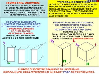
  • 1. H 3-D DRAWINGS CAN BE DRAWN IN NUMEROUS WAYS AS SHOWN BELOW. ALL THESE DRAWINGS MAY BE CALLED 3-DIMENSIONAL DRAWINGS, OR PHOTOGRAPHIC OR PICTORIAL DRAWINGS. HERE NO SPECIFIC RELATION AMONG H, L & D AXES IS MENTAINED. H NOW OBSERVE BELOW GIVEN DRAWINGS. ONE CAN NOTE SPECIFIC INCLINATION AMONG H, L & D AXES. ISO MEANS SAME, SIMILAR OR EQUAL. HERE ONE CAN FIND EQUAL INCLINATION AMONG H, L & D AXES. EACH IS 1200 INCLINED WITH OTHER TWO. HENCE IT IS CALLED ISOMETRIC DRAWING H L IT IS A TYPE OF PICTORIAL PROJECTION IN WHICH ALL THREE DIMENSIONS OF AN OBJECT ARE SHOWN IN ONE VIEW AND IF REQUIRED, THEIR ACTUAL SIZES CAN BE MEASURED DIRECTLY FROM IT. IN THIS 3-D DRAWING, AN OBJECT IS SO PLACED THAT, ITS THREE MUTUALLY PERPENDICULAR EDGES ARE EQUALLY INCLINED WITH THE PLANE OF PROJECTION. SO ALL THREE DIMENSIONAL AXES APPEAR AT EQUAL INCLINATIONS WITH EACH OTHER.( 1200 ) PURPOSE OF ISOMETRIC DRAWING IS TO UNDERSTAND OVERALL SHAPE, SIZE & APPEARANCE OF AN OBJECT PRIOR TO IT’S PRODUCTION. ISOMETRIC DRAWING TYPICAL CONDITION.
  • 2. ISOMETRIC AXES, LINES AND PLANES: The three lines AL, AD and AH, meeting at point A and making 1200 angles with each other are termed Isometric Axes. The lines parallel to these axes are called Isometric Lines. The planes representing the faces of of the cube as well as other planes parallel to these planes are called Isometric Planes. ISOMETRIC SCALE: When one holds the object in such a way that all three dimensions are visible then in the process all dimensions become proportionally inclined to observer’s eye sight and hence appear apparent in lengths. This reduction is 0.815 or 9 / 11 ( approx.) It forms a reducing scale which Is used to draw isometric drawings and is called Isometric scale. In practice, while drawing isometric projection, it is necessary to convert true lengths into isometric lengths for measuring and marking the sizes. This is conveniently done by constructing an isometric scale as described on next page. H A SOME IMPORTANT TERMS:
  • 3. X b 2 c 3 d 4 a 1 a’ d’ c’ b’ a’ d’ c’ b’ p’ p’ 3’ 3’ 1’ 2’ 4’ 2’ 4’ 1’ Y a1 b1 c1 d1 11 21 31 41 b1 c1 d1 11 21 41 c1’ b1’ d1’ 31’ 11’ a1’ 21’ 41’ Problem 13.23: A cube of 25 mm long edges is so placed on HP on one corner that a body diagonal is parallel to HP and perpendicular to VP Draw it’s projections. Solution Steps: 1.Assuming standing on HP, begin with TV,a square with all sides equally inclined to XY. Project FV and name all points of FV & TV. 2.Draw a body-diagonal joining c’ with 1’( This can become // to xy) 3.From 3’ drop a perpendicular on this and name it p’ 4.Draw 2nd Fv in which 3’p’ line is vertical means c’-1’ diagonal must be horizontal. .Now as usual project TV.. 6.In final TV draw same diagonal is perpendicular to VP as said in problem. Then as usual project final FV.
  • 4. ISOMETRIC VIEW ISOMETRIC PROJECTION H H TYPES OF ISOMETRIC DRAWINGS Drawn by using Isometric scale ( Reduced dimensions ) Drawn by using True scale ( True dimensions ) 450 300 0 1 2 3 4 0 1 2 3 4 TRUE LENG THS ISOM. LENGTHS Isometric scale [ Line AC ] required for Isometric Projection A B C D CONSTRUCTION OF ISOM.SCALE. From point A, with line AB draw 300 and 450 inclined lines AC & AD resp on AD. Mark divisions of true length and from each division-point draw vertical lines upto AC line. The divisions thus obtained on AC give lengths on isometric scale.
  • 5. SHAPE Isometric view if the Shape is F.V. or T.V. TRIANGLE A B RECTANGLE D C H L D A B C D A B D C L H L D L 1 2 3 A B 3 1 2 A B 3 1 2 A B H L D L 1 2 3 4 PENTAGON A B C D E 1 2 3 4 A B C D E 1 2 3 4 A B C D E ISOMETRIC OF PLANE FIGURES AS THESE ALL ARE 2-D FIGURES WE REQUIRE ONLY TWO ISOMETRIC AXES. IF THE FIGURE IS FRONT VIEW, H & L AXES ARE REQUIRED. IF THE FIGURE IS TOP VIEW, D & L AXES ARE REQUIRED. Shapes containing Inclined lines should be enclosed in a rectangle as shown. Then first draw isom. of that rectangle and then inscribe that shape as it is. 1
  • 6. 1 4 2 3 A B D C 1 4 2 3 A B D C Z STUDY ILLUSTRATIONS DRAW ISOMETRIC VIEW OF A CIRCLE IF IT IS A TV OR FV. FIRST ENCLOSE IT IN A SQUARE. IT’S ISOMETRIC IS A RHOMBUS WITH D & L AXES FOR TOP VIEW. THEN USE H & L AXES FOR ISOMETRIC WHEN IT IS FRONT VIEW. FOR CONSTRUCTION USE RHOMBUS METHOD SHOWN HERE. STUDY IT. 2
  • 7. 25 R 100 MM 50 MM Z STUDY ILLUSTRATIONS DRAW ISOMETRIC VIEW OF THE FIGURE SHOWN WITH DIMENTIONS (ON RIGHT SIDE) CONSIDERING IT FIRST AS F.V. AND THEN T.V. IF TOP VIEW IF FRONT VIEW 3
  • 8. CIRCLE HEXAGON SEMI CIRCLE ISOMETRIC OF PLANE FIGURES AS THESE ALL ARE 2-D FIGURES WE REQUIRE ONLY TWO ISOMETRIC AXES. IF THE FIGURE IS FRONT VIEW, H & L AXES ARE REQUIRED. IF THE FIGURE IS TOP VIEW, D & L AXES ARE REQUIRED. SHAPE IF F.V. IF T.V. For Isometric of Circle/Semicircle use Rhombus method. Construct Rhombus of sides equal to Diameter of circle always. ( Ref. topic ENGG. CURVES.) For Isometric of Circle/Semicircle use Rhombus method. Construct it of sides equal to diameter of circle always. ( Ref. Previous two pages.) 4
  • 9. D L 1 2 3 4 A B C D E D L 1 2 3 4 A B C D E ISOMETRIC VIEW OF PENTAGONAL PYRAMID STANDING ON H.P. (Height is added from center of pentagon) ISOMETRIC VIEW OF BASE OF PENTAGONAL PYRAMID STANDING ON H.P. Z STUDY ILLUSTRATIONS 5
  • 10. H L 1 2 3 4 A B C D E Z STUDY ILLUSTRATIONS ISOMETRIC VIEW OF PENTAGONALL PRISM LYING ON H.P. ISOMETRIC VIEW OF HEXAGONAL PRISM STANDING ON H.P. 6
  • 11. Z STUDY ILLUSTRATIONS CYLINDER LYING ON H.P. CYLINDER STANDING ON H.P. 7
  • 12. Z STUDY ILLUSTRATIONS HALF CYLINDER LYING ON H.P. ( with flat face // to H.P.) HALF CYLINDER STANDING ON H.P. ( ON IT’S SEMICIRCULAR BASE) 8
  • 13. Z STUDY ILLUSTRATIONS ISOMETRIC VIEW OF A FRUSTOM OF SQUARE PYRAMID STANDING ON H.P. ON IT’S LARGER BASE. 40 20 60 X Y FV TV 9
  • 14. ISOMETRIC VIEW OF FRUSTOM OF PENTAGONAL PYRAMID 4 0 2 0 60 STUDY ILLUSTRATION 1 2 3 4 y A B C D E 40 20 60 x FV TV PROJECTIONS OF FRUSTOM OF PENTAGONAL PYRAMID ARE GIVEN. DRAW IT’S ISOMETRIC VIEW. SOLUTION STEPS: FIRST DRAW ISOMETRIC OF IT’S BASE. THEN DRAWSAME SHAPE AS TOP, 60 MM ABOVE THE BASE PENTAGON CENTER. THEN REDUCE THE TOP TO 20 MM SIDES AND JOIN WITH THE PROPER BASE CORNERS. 10
  • 15. Z STUDY ILLUSTRATIONS ISOMETRIC VIEW OF A FRUSTOM OF CONE STANDING ON H.P. ON IT’S LARGER BASE. FV TV 40 20 60 X Y 11
  • 16. 50 Z STUDY ILLUSTRATIONS PROBLEM: A SQUARE PYRAMID OF 30 MM BASE SIDES AND 50 MM LONG AXIS, IS CENTRALLY PLACED ON THE TOP OF A CUBE OF 50 MM LONG EDGES.DRAW ISOMETRIC VIEW OF THE PAIR. 50 3 0 12
  • 17. a b c o p p a b c o Z STUDY ILLUSTRATIONS PROBLEM: A TRIANGULAR PYRAMID OF 30 MM BASE SIDES AND 50 MM LONG AXIS, IS CENTRALLY PLACED ON THE TOP OF A CUBE OF 50 MM LONG EDGES. DRAW ISOMETRIC VIEW OF THE PAIR. SOLUTION HINTS. TO DRAW ISOMETRIC OF A CUBE IS SIMPLE. DRAW IT AS USUAL. BUT FOR PYRAMID AS IT’S BASE IS AN EQUILATERAL TRIANGLE, IT CAN NOT BE DRAWN DIRECTLY.SUPPORT OF IT’S TV IS REQUIRED. SO DRAW TRIANGLE AS A TV, SEPARATELY AND NAME VARIOUS POINTS AS SHOWN. AFTER THIS PLACE IT ON THE TOP OF CUBE AS SHOWN. THEN ADD HEIGHT FROM IT’S CENTER AND COMPLETE IT’S ISOMETRIC AS SHOWN. 13
  • 18. Z STUDY ILLUSTRATIONS 50 50 30 D 30 10 30 + FV TV PROBLEM: A SQUARE PLATE IS PIERCED THROUGH CENTRALLY BY A CYLINDER WHICH COMES OUT EQUALLY FROM BOTH FACES OF PLATE. IT’S FV & TV ARE SHOWN. DRAW ISOMETRIC VIEW. 14
  • 19. Z STUDY ILLUSTRATIONS 30 10 30 60 D 40 SQUARE FV TV PROBLEM: A CIRCULAR PLATE IS PIERCED THROUGH CENTRALLY BY A SQUARE PYRAMID WHICH COMES OUT EQUALLY FROM BOTH FACES OF PLATE. IT’S FV & TV ARE SHOWN. DRAW ISOMETRIC VIEW. 15
  • 20. Z STUDY ILLUSTRATIONS X Y 30 D 50 D 10 40 20 40 FV TV F.V. & T.V. of an object are given. Draw it’s isometric view. 16
  • 21. P r R R r P C C = Center of Sphere. P = Point of contact R = True Radius of Sphere r = Isometric Radius. R r I s o - D i r e c t i o n P r R C r r ISOMETRIC PROJECTIONS OF SPHERE & HEMISPHERE r R 450 300 TO DRAW ISOMETRIC PROJECTION OF A HEMISPHERE TO DRAW ISOMETRIC PROJECTION OF A SPHERE 1. FIRST DRAW ISOMETRIC OF SQUARE PLATE. 2. LOCATE IT’S CENTER. NAME IT P. 3. FROM PDRAW VERTICAL LINE UPWARD, LENGTH ‘ r mm’ AND LOCATE CENTER OF SPHERE “C” 4. ‘C’ AS CENTER, WITH RADIUS ‘R’ DRAW CIRCLE. THIS IS ISOMETRIC PROJECTION OF A SPHERE. Adopt same procedure. Draw lower semicircle only. Then around ‘C’ construct Rhombus of Sides equal to Isometric Diameter. For this use iso-scale. Then construct ellipse in this Rhombus as usual And Complete Isometric-Projection of Hemi-sphere. Z STUDY ILLUSTRATIONS Isom. Scale 17
  • 22. P r R r r 50 D 30 D 50 D 50 r R 450 300 PROBLEM: A HEMI-SPHERE IS CENTRALLY PLACED ON THE TOP OF A FRUSTOM OF CONE. DRAW ISOMETRIC PROJECTIONS OF THE ASSEMBLY. FIRST CONSTRUCT ISOMETRIC SCALE. USE THIS SCALE FOR ALL DIMENSIONS IN THIS PROBLEM. Z STUDY ILLUSTRATIONS 18
  • 23. a b c d 1 2 3 4 o 1’ 4’ 3’ 2’ 1 2 4 3 X Y Z STUDY ILLUSTRATIONS A SQUARE PYRAMID OF 40 MM BASE SIDES AND 60 MM AXIS IS CUT BY AN INCLINED SECTION PLANE THROUGH THE MID POINT OF AXIS AS SHOWN.DRAW ISOMETRIC VIEW OF SECTION OF PYRAMID. 19
  • 24. Z STUDY ILLUSTRATIONS X Y 50 20 25 25 20 O O F.V. & T.V. of an object are given. Draw it’s isometric view. 20
  • 25. Z STUDY ILLUSTRATIONS x y FV TV 35 35 10 30 20 10 40 70 O O F.V. & T.V. of an object are given. Draw it’s isometric view. 21
  • 26. Z STUDY ILLUSTRATIONS x y FV SV TV 30 30 10 30 10 30 ALL VIEWS IDENTICAL F.V. & T.V. and S.V.of an object are given. Draw it’s isometric view. 22
  • 27. x y FV SV TV Z STUDY ILLUSTRATIONS 10 40 60 60 40 ALL VIEWS IDENTICAL F.V. & T.V. and S.V.of an object are given. Draw it’s isometric view. 24
  • 28. x y FV SV TV ALL VIEWS IDENTICAL 40 60 60 40 10 F.V. & T.V. and S.V.of an object are given. Draw it’s isometric view. Z STUDY ILLUSTRATIONS 25
  • 29. ORTHOGRAPHIC PROJECTIONS FRONT VIEW TOP VIEW L.H.SIDE VIEW x y 20 20 20 50 20 20 20 20 30 O O F.V. & T.V. and S.V.of an object are given. Draw it’s isometric view. Z STUDY ILLUSTRATIONS 26
  • 30. 40 20 30 SQUARE 20 50 60 30 10 F.V. S.V. O O F.V. and S.V.of an object are given. Draw it’s isometric view. Z STUDY ILLUSTRATIONS 27
  • 31. 40 10 50 80 10 30 D 45 FV TV O O F.V. & T.V. of an object are given. Draw it’s isometric view. Z STUDY ILLUSTRATIONS 28
  • 32. O FV TV X Y O 40 10 25 25 30 R 10 100 10 30 10 20 D F.V. & T.V. of an object are given. Draw it’s isometric view. Z STUDY ILLUSTRATIONS 29
  • 33. O O 10 30 50 10 35 20 D 30 D 60 D FV TV X Y RECT. SLOT F.V. & T.V. of an object are given. Draw it’s isometric view. Z STUDY ILLUSTRATIONS 30
  • 34. O 10 O 40 25 15 25 25 25 25 80 10 F.V. S.V. F.V. and S.V.of an object are given. Draw it’s isometric view. Z STUDY ILLUSTRATIONS 31
  • 35. O 450 X TV FV Y 30 D 30 40 40 40 15 O F.V. & T.V. of an object are given. Draw it’s isometric view. Z STUDY ILLUSTRATIONS 32
  • 36. O O 20 20 15 30 60 30 20 20 40 100 50 HEX PART F.V. and S.V.of an object are given. Draw it’s isometric view. Z STUDY ILLUSTRATIONS 33
  • 37. O O 10 10 30 10 30 40 20 80 30 F.V. T.V. X Y F.V. & T.V. of an object are given. Draw it’s isometric view. Z STUDY ILLUSTRATIONS 34
  • 38. FV LSV X Y 10 O FV LSV X Y 10 10 15 25 25 10 50 O F.V. and S.V.of an object are given. Draw it’s isometric view. Z STUDY ILLUSTRATIONS 35 36 NOTE THE SMALL CHZNGE IN 2ND FV & SV. DRAW ISOMETRIC ACCORDINGLY.
  • 39. Y X F.V. LEFT S.V. 30 20 20 10 15 15 15 30 50 10 15 O O F.V. and S.V.of an object are given. Draw it’s isometric view. Z STUDY ILLUSTRATIONS 37
  • 40. 30 40 10 60 30 40 F.V. S.V. O O F.V. and S.V.of an object are given. Draw it’s isometric view. Z STUDY ILLUSTRATIONS 38