
Recommended
More Related Content
What's hot
What's hot (20)
Similar to Lec 2 ohms law, voltage source & current source
Similar to Lec 2 ohms law, voltage source & current source (20)
Recently uploaded
Recently uploaded (20)
Lec 2 ohms law, voltage source & current source
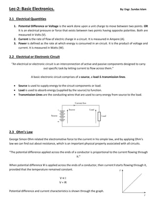
- 1. Lec-2: Basic Electronics. By: Engr. Sundas Islam 2.1 Electrical Quantities 1. Potential Difference or Voltage is the work done upon a unit charge to move between two points. OR It is an electrical pressure or force that exists between two points having opposite polarities. Both are measured in Volts (V). 2. Current is the rate of flow of electric charge in a circuit. It is measured in Ampere (A). 3. Power is defined as the rate at which energy is consumed in an circuit. It is the product of voltage and current. It is measured in Watts (W). 2.2 Electrical or Electronic Circuit “An electrical or electronic circuit is an interconnection of active and passive components designed to carry out specific task by letting current to flow across them.” A basic electronic circuit comprises of a source, a load & transmission lines. Source is used to supply energy to the circuit components or load. Load is used to absorb energy (supplied by the source) to function. Transmission Lines are the conducting wires that are used to carry energy from source to the load. 2.3 Ohm’s Law George Simon Ohm related the electromotive force to the current in his simple law, and by applying Ohm’s law we can find out about resistance, which is an important physical property associated with all circuits. “The potential difference applied across the ends of a conductor is proportional to the current flowing through it.” When potential difference V is applied across the ends of a conductor, then current I starts flowing through it, provided that the temperature remained constant. V ∝ I V = IR Potential difference and current characteristics is shown through the graph.
- 2. 2.4 Series & Parallel connections for Resistive Circuit 1. Series Circuit A series circuit is a circuit in which resistors / electronic components are arranged in a chain, so the current has only one path to take. In series circuit, The same current I flows across every circuit component. The total voltage equals the sum of the voltages across the different components of the circuit. V = V1 + V2 + V3 IR = IR1 + IR2 + IR3 I R = I (R1 + R2 + R3) The total resistance of the circuit is the sum of resistance offered by every component connected in series. R = R1 + R2 + R3 1.a Open Series Circuit An open circuit results in no current in all parts of the series circuit. For an open in a series circuit, the voltage across the two open terminals is equal to the applied voltage, and the voltage across the remaining components is 0 V. a) The current I is zero in all components. b) The voltage drop across each good component is 0 V. c) The voltage across the open points equals the applied voltage. 1.b Short Series Circuit A short in a series circuit causes the current to increase above its normal value. The voltage drop across the shorted component decreases to 0 V, and the voltage drop across the remaining components increases. a) The current I increases above its normal value. b) The voltage drop across each good component increases. c) The voltage drop across the shorted component drops to 0 V. 2. Parallel Circuit is a circuit in which one end of all resistors / electronic component is connected to the positive terminal of the battery and other end of all resistors / electronic component is connected to the negative terminal of the battery. In parallel circuit, The voltage across every component is same as that of supplied voltage Vs to the circuit. The total current supplied to the network equals the sum of the currents in the various branches.
- 3. I = I1 + I2 + I3 The reciprocal of the total resistance of the circuit is the sum of the reciprocals of the branch resistances. 2.a Open Parallel Circuit: An open circuit in one branch results in no current through that branch, but the other branches can have their normal current. However, an open circuit in the main line results in no current for any of the branches and the current I is zero in all components. a) The Current I decreases below its normal value in main line if anyone of the component has been opened. b) Except the open circuit branch, current in other branches is normal. c) The voltage across each component and the open points equals the applied voltage. 2.b Short Parallel Circuit: A short circuit has zero resistance, resulting in excessive current. When one branch is short- circuited, all parallel paths are also short-circuited. The entire current is in the short circuit and no current is in the short circuited branches. a) The current I increases above its normal value. b) The voltage drop across the short circuit drops to 0 V. c) For the short circuit as shown in the Figure, the I is 0 A in the
- 4. parallel resistors R1 and R2. The reason is that the short circuit is a parallel path with practically zero resistance. Then all the current flows in this path, bypassing the resistors R1 and R2. Therefore R1 and R2 are short-circuited or shorted out of the circuit. The short-circuited components are not damaged. 2.4 Comparison of Series and Parallel Resistive Circuits S. No Series Circuit Parallel Circuit 1. Current is same in all components. Voltage is same across all branches. 2. V across each series R is I R I in each branch R is 3. VT = V1 + V2 + V3 + … + etc. IT = I1 + I2 + I3 + … + etc. 4. RT = R1 + R2 + R3 + … + etc. 5. RT must be more than the largest individual R. REQ must be less than the smallest branch R. 6. PT = P1 + P2 + P3 + … + etc PT = P1 + P2 + P3 + … + etc 7. Applied voltage is divided into IR voltage drops. Main-line current is divided into branch currents 8. The largest IR drop is across the largest series R The largest branch I is in the smallest parallel R 9. Open in one component causes entire circuit to be opened, dropping maximum voltage (equivalent to source voltage) across the opened terminals. Open in one branch does not prevent current flow into other branches. 10. Any component replaced by short circuit does not prevent current flow into other components & will maximize voltage drop across other components. Any branch replaced by short circuit causes entire circuit to flow through the short circuit bypassing all other branches. 2.5 Voltage Source and Current Source 1. Voltage Source Any device that produces voltage output continuously is known as a voltage source. There are two types of voltage sources, namely; direct voltage source and alternating voltage source. a. Direct Voltage Source A device which produces direct voltage output continuously is called a direct voltage source. Common examples are batteries, cells and d.c. generators. b. Alternating Voltage Source A device which produces alternating voltage output continuously is known as alternating voltage source e.g. a.c. generator.
- 5. 2. Constant Voltage Source A dc voltage source which has very low internal impedance as compared with external load impedance is known as a constant voltage source. Voltage source is always connected in series with the internal resistance. 3. Constant Current Source A dc voltage source that has very high internal impedance as compared with external load impedance is considered as a constant current source. Voltage source is always connected in parallel to the internal resistance.