
Recommended
More Related Content
Similar to Machining of composites .pdf
Similar to Machining of composites .pdf (20)
Recently uploaded
Recently uploaded (20)
Machining of composites .pdf
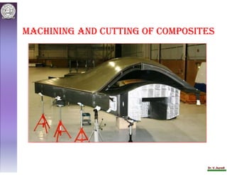
- 1. Dr. V. Auradi Machining and cutting of coMposites
- 2. Dr. V. Auradi Composite materials offer the benefits of part integration and thus minimize the requirement for machining operations. However, machining operations cannot be completely avoided and most of the components have some degree of machining. Machining operations are extensively used in the aerospace industry. In a typical aerospace application, assembly and sub-assembly labor costs account for as much as 50% of the total manufacturing costs of current airframes. A fighter plane has between 250,000 and 400,000 holes and a bomber transport has between 1,000,000 and 2,000,000 holes; A typical wing on an aircraft may have as many as 5000 holes. Therefore, machining cost has become major production cost factor in aerospace applications.
- 3. Dr. V. Auradi Objectives/Purposes of Machining To create holes, slots, and other features that are not possible to obtain during manufacturing of the part. For example, if a pultruded part needs holes and other features as shown in Figure then machining of the part is unavoidable. Machining is done to create the desired tolerance in the component. For example, if a filament wound part requires the outside diameter to have a tolerance of 0.002 in., then centerless grinding is done to get that tolerance on the outer surface.
- 4. Dr. V. Auradi Machining is performed to prepare the surface for bonding, coating, and painting purposes. In general, the outer surface is sanded to remove oils, grease, and release agents. Machining is performed to create smoothness on the desired surface. To make prototype parts from a big blank or sheet of material, machining operation is performed. This process is very economical. For example, if a designer wants to test glass/nylon short fiber composites for a bushing application, he can machine a composite rod/tube to develop a prototype part instead of making an expensive mold. Similarly, test coupons for tensile and bond testing are made from big sheets of materials.
- 5. Dr. V. Auradi Challenges during Machining of Composites Machining of composite parts creates discontinuity in the fiber and thus affects the performance of the part. Machining exposes fibers to chemicals and moisture. The temperature during cutting should not exceed the cure temperature of the resin for thermoset composites to avoid material disintegration. Glass and Kevlar fibers have poor thermal conductivity and such high temperatures may lead to localized heating and degradation. With thermoplastic composites, if the temperature comes close to the melting temperature of the resin, it may clog the tool. It is difficult to attain dimensional accuracy during the cutting of composites because of differences in the coefficients of thermal expansion (CTE) in the matrix (highly positive CTE) and fiber (slightly negative CTE in carbon and aramid). Drilled holes are often found to be smaller than the drill used.
- 6. Dr. V. Auradi There is heat build-up in the cutting zone due to the low thermal conductivity of the composite. A suitable coolant should be selected to dissipate the heat from the tool and the work piece. In drilling metal components, chips absorb 75% of total heat, whereas the tool and work piece absorb 18 and 7%, respectively. In the drilling of carbon/epoxy composites, the tool absorbs half of the heat and remainder is equally absorbed by work piece and chips. Tool life is usually shorter because of the abrasive nature of the composite. For this reason, high-speed steel tools are coated with tungsten carbide or titanium nitride to increase the life of the tool. Obtaining a smooth cut edge is difficult with composites, especially aramid composites. Aramid fibers are tough and absorb the cutting energy. Fiber kinking or burr surfaces are obtained during cutting of aramid composites. The effect of coolant materials on composites is unknown and therefore any coolant material must be selected judiciously.
- 7. Dr. V. Auradi Machining of composites causes delaminations at the cut edges of continuous composites. The lay-up sequence and fiber orientations have a significant effect on the amount of delamination.
- 8. Dr. V. Auradi Cutting Tools Cutting tools similar to those in metal machining are used for composites as well. However, high-speed steel (HSS) tools are coated with tungsten carbide, titanium nitride, or diamond to avoid excessive wear on the tool. HSS tools without any coating performs reasonably well for a few cuts; but after a while, the tool edge becomes dull and the cut quality deteriorates. In terms of tool life, carbide tools are superior, especially if carbide grades of fine grain size are used. However, tool cost is considerably higher. Polycrystalline diamond (PCD) tools are extensively used for machining glass and carbon-reinforced composites due to their high wear resistance. PCD tools cost about 10 times more than carbide tools.
- 9. Dr. V. Auradi Figure shows end mills and drills for machining composites and shows inserts for turning, boring, and milling operations. These tools are coated with diamond in a chemical vapor deposition (CVD) reactor and the result is called CVDD (CVD Diamond). The CVDD coating is pure diamond with no metallic binder. CVDD- coated tools are less costly than PCD tools. Usually, there is no coolant necessary while using CVDD tools because of the lubricity of the diamond. A coolant (such as 5% water soluble oil) can sometimes be used to improve the surface finish and/or to enhance chip clearing.
- 10. Dr. V. Auradi Choosing the correct diamond coating thickness is very critical to the success of an application. For example, to machine fiberglass composites (commercially available G10), a 20- to 24- m thick coating works very well and it is 65 times better in sliding and 30 times better in side milling as compared to carbide tools. A 10 to 14 m thick diamond coating does not work well for machining G10 fiberglass composites. During the slotting test, the carbide tool machined 192 linear inches before three corners were worn away, whereas the CVD tool with a 20- m thick coating machined 12,384 linear inches before one corner wore away. A CVD tool with 10- m thick coating machined 480 linear inches before one corner wore away.
- 11. Dr. V. Auradi Types of Machining Operations Machining operations are performed to achieve various objectives The operation involves cutting, drilling, sanding, grinding, milling, and other techniques similar to metal machining. Standard machining equipment similar to metal machining is used with some modifications, mostly in the cutting tool and coolant. In all machining operations, it is important to keep the tool sharp to obtain good-quality cuts and to avoid delaminations. During the machining of composites, the proper backing material is required to avoid delamination. Two of the major machining operations — cutting and drilling — are discussed in the following sections.
- 12. Dr. V. Auradi Cutting Operation Conversion of a flat sheet and rod into smaller pieces The cutting operation is performed to get the desired dimensions or to make Several parts from one part. For example, a large sheet of FRP is cut into small rectangular strips, or any other shape, as shown in Figure Sometimes, the cutting operation is performed to fabricate net-shape parts. Flashes, runners, shear edges, etc. obtained during molding processes are removed by cutting operations. For example, during compression molding of electronic enclosures or automotive parts, shear edges are trimmed using a file while the part is still hot.
- 13. Dr. V. Auradi Cutting operations are performed using hand-held hacksaws, bend saws, circular saws, abrasive files, routers, and more. The tool is diamond coated for increased wear resistance. During machining, the cutting speed should be selected based on the matrix, better cut quality. The higher cutting speed means lower cut forces perpendicular to the work piece and feed direction, which consequently reduces the amount of manufacturing induced damages. Now a days, waterjet cutting and laser cutting are gaining more importance and is discussed here.
- 14. Dr. V. Auradi Waterjet Cutting Waterjet cutting is used for machining composites ; sheet metals made of steel and aluminum. In waterjet cutting, high-velocity water is forced through a small- diameter jet. As the waterjet impinges on the surface, it cuts the material by inducing a localized stress failure and eroding the material.
- 15. Dr. V. Auradi In waterjet cutting, water pressures up to 60,000 psi (414 MPa) are used to cut the material. Water speeds of 2600 ft/s (800 m/s) and nozzle diameters on the order of 0.010 in. (0.25 mm) are typical. For most composite applications, abrasive particles are added with the water to increase the cutting speed and to cut thick composite laminates. A schematic diagram of commercially available waterjet cutting equipment is shown in Figure As shown, the water nozzle remains stationary and the sample material travels by a hydraulic cylinder. A 30-gpm (113.5l/min) hydraulic pump delivers hydraulic oil at up to 3000 psi (21 MPa) to an intensifier via a four-way valve. The intensifier is a differential-area, double-acting piston type in which a large piston is shuttled back and forth by the 3000 psi oil.
- 16. Dr. V. Auradi There are two small pistons attached directly to the large piston. The small pistons have an area 1/20th of the large piston; thus it converts the 3000-psi oil to 60,000 psi water. Compressed water then flows out of the high-pressure cylinders to the nozzle through a pair of check valves. During waterjet cutting, the process parameters that affect cutting performance include: Waterjet pressure Cutting speed Laminate thickness Nozzle orifice diameter (0.2–8 mm)
- 17. Dr. V. Auradi Laser Cutting In laser cutting, a concentrated monochromatic raw light beam is focused on the work-piece into a spot size of 0.1 to 1 mm. The cutting operation takes place by local melting, vaporization, and chemical degradation. Laser operation requires expertise because of the danger of high- voltage radiation exposure and hazardous fumes. The laser beam typically damages the resin in the areas of the cut and may score the work-stand. Proper ventilation is required while performing the laser cutting operation. Cutting of unreinforced thermoplastics and thermosets is much easier than for reinforced composites. Cutting thermoplastics results in local melting, whereas laser cutting of thermosets results in local vaporization and chemical degradation.
- 18. Dr. V. Auradi Once reinforcements are included into the resin, very high temperatures are required to vaporize the fibers. Vaporization temperature for carbon fiber is 3300°C, E-glass fiber is 2300°C, and aramid fiber is 950°C. The high-temperature requirement for cutting reinforced plastic results in local matrix degradation. Laser cutting produces a sharp, clean edge with little discoloration at speeds unrivaled by other cutting methods for prepregs (uncured composites). Continuous-wave 250-W CO2 lasers have produced cutting speeds up to 300 in/min (127 mm/s) in single-ply uncured boron/epoxy and up to 400 in./min (169 mm/s) in single-ply Kevlar pre-pregs. Cutting of cured composites requires higher laser power and cut edges generally reveal a charring effect. Charring can be reduced in thinner materials by increasing the speed. A 1-kW laser can cut up to 0.2 in. (5 mm) thick Kevlar/epoxy
- 19. Dr. V. Auradi Drilling Operation The drilling operation is performed to create holes in a component. Holes are created either for fastening purposes, such as riveting or bolting, or for creating special features, such as a passage for liquid injection or wire connection. Drilling is performed similar to metal drilling but the tool used is usually a tungsten carbide tool because of the abrasive nature of composites. In metal drilling, drill tips are designed for metal-working, the tip heating the metal to provide the plastic flow needed for efficient cutting. In composites, heat generation is kept low to avoid local matrix degradation and/or to avoid tool clogging. The chip formation in metal drilling is long; whereas in composites, chips are dry and small, and can be easily removed. If the drilling speed is high, then local heat generation makes the resin sticky and produces a lumpy chip.
- 20. Dr. V. Auradi Drilling creates delaminations in laminated composites, as shown in Figures delaminations caused by drilling (a) upon entry, and (b) upon exit. When the drill bit first enters the laminate, it peels up the uppermost laminae (Figure a); and when it leaves the laminate, it acts as a punch, causing delaminations on the other side of the laminate as shown in Figure b. Delamination on the other side can be minimized by supporting the laminate at the back side using a plastic or wooden support, and also by lowering the feed rate at the time of exit.
- 21. Dr. V. Auradi A more pointed drill bit tip also lowers the amount of delamination, because a pointed tip creates gradual penetration. In drilling composites, a negative or neutral rake angle in the tool is avoided. A neutral rake angle tends to push the reinforcing fibers out in front, requiring a great deal of pressure to penetrate the workpiece. This pressure causes the fibers to bend, resulting in undersized and furry holes. Moreover, this pressure produces excessive heat, which causes galling and clogging of the tool. A positive rake angle is preferred when designing the tool geometry for composites drilling. With a positive rake angle, reinforcing fibers are pulled into the workpiece and sheared or broken between the cutting edge and the uncut material.
- 22. Dr. V. Auradi Positive rake removes more material per unit of time and per unit of pressure than negative rake, but the more positive rake at cutting edge makes the tool sensitive and fragile. Fiber orientation and lay-up sequence affect the extent of delamination during drilling. Angle-ply laminates provide better-machined surfaces than unidirectional laminates. In unidirectional composites, fibers tend to pull out of matrix when the local motion between tool and workpiece is parallel to the fibers (0°). The best surface quality is obtained when fibers are sheared off at a right angle (90°), while the worst surface is obtained when fibers are compressed and bent, which occurs at intermediate angles (20° to 45°).