1. Erik Venini MECHANICAL ENGINEERING
636 East 18th Ave, Vancouver, BC
erik.venini92@gmail.com - 1.604.500.5232
3D printing is widely recognized as a promising technology in many fields, however its biomedical
applications seem to be underestimated.
Traditional methods of manufacturing are much more efficient when it comes to producing large quantities
of the same product. Casting, molding and forming require large amounts of machineryand preparation, but
can produce virtually any shape in any material, replicated thousands of times. Additive manufacturing
(printing) requires only the printer and the 3D file to be printed, and is practically incapable of producingan
identical shape twice, which - when designing for the human body - is actually an advantage over
traditional methods.
As technologies such as 3D scanning and 3D modelling become faster and more intuitive, 3D printing is
the only manufacturing method flexible enough to produce individual parts suitable for dynamic human
shapes.
The Victoria Hand Project is an organization based at the University of Victoria that develops low cost, 3D
printed prosthetic hands for amputees in developing countries. The VHP currently has printing stations
operating in Guatemala and Nepal, and is able to print a custom fit prosthetic arm for much less than that of
traditional prosthetics.
Soon after expressing my interest to the VHP team, I was put in charge of designing a 3D printed ankle
brace for ankle sprains and added ankle support.
I began by researching existing ankle braces and orthopaedic supports, and discovered that the Air Cast
design is the most common solution for ankle sprains. Their simple design wraps around the ankle,
underneath the heel, preventing ankle inversion and eversion (rolling), while allowing some plantar flexion
and dorsiflexion so that the user can remain mobile.
Using 3D printed PLA plastic, I was able to create a simple design and use thermoforming (hot water
molding) to wrap the brace around the individual’s ankle, creating a much better fit.
2. Erik Venini MECHANICAL ENGINEERING
636 East 18th Ave, Vancouver, BC
erik.venini92@gmail.com - 1.604.500.5232
Figure 1: A flat Solidworks model of the ankle brace. Holes are designed into the brace to allow for
airflow, to save on material costs, and to better accommodate the fibula and medial malleolus (ankle
bones) when thermoforming.
571.33
105
30
30
Velcro strap X4
B
C
D
1 2
A
321 4
B
A
5 6
DRAWN
CHK'D
APPV'D
MFG
Q.A
UNLESS OTHERWISE SPECIFIED:
DIMENSIONS ARE IN MILLIMETERS
SURFACE FINISH:
TOLERANCES:
LINEAR:
ANGULAR:
FINISH: DEBUR AND
BREAK SHARP
EDGES
NAME SIGNATURE DATE
MATERIAL:
DO NOT SCALE DRAWING REVISION
TITLE:
DWG NO.
SCALE:1:5 SHEET 1 OF 1
A4
C
ABS Plastic (3mm thick)
WEIGHT:
EV 11.04.16
ABS Printed Ankle Brace
3. Erik Venini MECHANICAL ENGINEERING
636 East 18th Ave, Vancouver, BC
erik.venini92@gmail.com - 1.604.500.5232
Figure 2: Version 1 of the ankle brace after thermoforming was applied. The thermoforming process
was as simple as setting the brace in hot water, then pressing and holding it around the ankle until it
solidified. Although the brace was molded around the ankle, there was still some discomfort while
standing.
4. Erik Venini MECHANICAL ENGINEERING
636 East 18th Ave, Vancouver, BC
erik.venini92@gmail.com - 1.604.500.5232
Figure 3: Second version of the ankle brace. To reduce discomfort noticed in the first design, the
second version was designed to have no material in contact with the ankle. This design would also
reduce material costs.
5. Erik Venini MECHANICAL ENGINEERING
636 East 18th Ave, Vancouver, BC
erik.venini92@gmail.com - 1.604.500.5232
Figure 4: Version 2 of the brace after printing. Printing supports and excess plastic have been removed.
Horizontal striations can be seen in the brace due to the printing orientation. Ideally, these striations
would be in line with the primary stress direction of the brace (vertical, in this case).
6. Erik Venini MECHANICAL ENGINEERING
636 East 18th Ave, Vancouver, BC
erik.venini92@gmail.com - 1.604.500.5232
Figure 5: The Version 2 brace after thermoforming. This design was more comfortable around the ankle,
however some dimensions needed to be widened. It was also noted that the straps in this design
should be lowered to apply force closer to the ankle. The top 20cm of the brace are unnecessary.
Figure 6: Version 3 of the brace before printing. In this version, the ankle space is widened, the brace is
shortened vertically, the straps are moved closer to the ankle, and sharp corners are smoothed out.
7. Erik Venini MECHANICAL ENGINEERING
636 East 18th Ave, Vancouver, BC
erik.venini92@gmail.com - 1.604.500.5232
Figure 7: Version 3 after printing, before thermoforming.
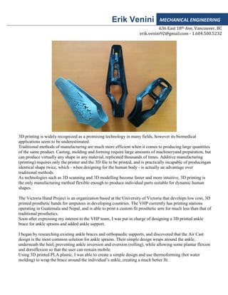
Figure 8: Ankle brace version 3 after forming to the ankle. This version is much more comfortable
due to enlarged ankle space, and provides more pressure to the affected area because of the lowered
strap positions. As seen above, the brace fits nicely into a low-top shoe.
The next steps are to optimize the shape around the ankle to improve comfort, and to improve strap
material and connection/adjustment methods.
8. Erik Venini MECHANICAL ENGINEERING
636 East 18th Ave, Vancouver, BC
erik.venini92@gmail.com - 1.604.500.5232
While I have made good progress towards a useful, comfortable, and cost effective ankle brace, there is
still much to do before the brace is ready for widespread use.
The next steps will be to consult an orthopaedic surgeon or orthotist to make sure the brace supports the
ankle in the most beneficial way. Straps must be chosen, and a thin foam layer may be added inside the
brace for more comfort. Alternate printing materials such as nylon will also be tested to increase strength
and flexibility.
After the completion of this project, I am excited to begin designing braces for wrists, arms, and full-limb
casts, as well as prosthetics!
This is a small project in a very promising field, and the idea of creating a product that directly impacts
someone’s quality of life is very exciting to me. As I take my Masters program at Simon Fraser Uniersity, I
intend to continue work for the Victoria Hand Project, and hope to start similar projects at SFU.