

Recommended
More Related Content
What's hot
What's hot (17)
Viewers also liked
Similar to RLC MOUNT
Recently uploaded
Recently uploaded (10)
RLC MOUNT
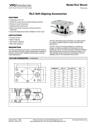
- 1. Technical contact: vpgt.americas@vpgsensors.com, vpgt.asia@vpgsensors.com, and vpgt.emea@vpgsensors.com Revere www.vpgtransducers.com 1 Model RLC Mount Document No.: 11881 Revision: 19 Dec 2014 RLC Self-Aligning Accessories FEATURES • Capacities: 0.25–10T • Hardened components at all load bearing surfaces • Rocker pin load introduction • Stainless steel construction • Built-in horizontal movement control and lift-off protection • Load cell (re)placement after installation of the mount APPLICATIONS • Process control • Batch weighing • Silo/hopper weighing • Belt scale weighing DESCRIPTION The RLC self-aligning silo mount, combined with the RLC load cell family, provides weighing assemblies suitable for process control, batch weighing, silo/hoppers, and belt scale applications. RLC Self-Aligning Accessories The RLC self-aligning foot assembly is an ideal solution for medium capacity platform scales and belt scale applications. The RLC mount and foot are based on a rocker pin design, combining excellent load introduction to the transducer with an overall low profile. Hardened stainless steel components are used at all bearing surfaces. The fully stainless steel construction guarantees long term reliability, even in the harshest environments. OUTLINE DIMENSIONS in millimeters CAPACITY 0.5T, 1T 2T, 3.5T, 5T 10T A 150 160 210 B 100 110 120 C 75 100 110 D 120 120 175 E 70 70 85 F 15 20 20 G 20 20 30 V ∅13 ∅16 ∅18
- 2. Technical contact: vpgt.americas@vpgsensors.com, vpgt.asia@vpgsensors.com, and vpgt.emea@vpgsensors.com Revere www.vpgtransducers.com 2 Model RLC Mount Document No.: 11881 Revision: 19 Dec 2014 RLC Self-Aligning Accessories ACCESSORIES Self-Aligning Mount The stainless steel RLC mount tolerates controlled movement in all directions. The silo or hopper is held captive, eliminating the need, unless major load movement is anticipated, for additional check rods. The unique design allows the load cell to be placed or replaced after installation of the mount. Non-Adjustable Foot The non-adjustable, stainless steel foot carries the same specifications as the height adjustable version, while providing an even lower profile. Height-Adjustable Foot This stainless steel foot, which has 5 mm of height adjustment, provides excellent load introduction to the load cell. The foot allows flexibility in platform design without compromising overall system performance. ADDITIONAL INFORMATION MOUNT/FOOT 0.25–1T 2–5T 10T Self-aligning mount Height, mount assembly + RLC (mm) 75 100 110 Outline drawing 899043-00 899045-00 499094-10 Mount assembly guideline AG 05/7-100/01 AG 05/7-100/01 - Non-adjustable foot Height of non-adjustable foot + RLC (mm) 50 85.2 - Outline drawing non-adjustable foot 899041-00 899042-00 - Height-adjustable foot Height of adjustable foot + RLC (mm) 60+5 92.6+5 120.2+5 Outline drawing adjustable foot 499083-00 499084-00 499093-00
- 3. Vishay Precision Group, Inc. www.vpgsensors.com 1 Legal Disclaimer Notice Document No.: 63999 Revision: 15-Jul-2014 Disclaimer ALL PRODUCTS, PRODUCT SPECIFICATIONS AND DATA ARE SUBJECT TO CHANGE WITHOUT NOTICE. Vishay Precision Group, Inc., its affiliates, agents, and employees, and all persons acting on its or their behalf (collectively, “VPG”), disclaim any and all liability for any errors, inaccuracies or incompleteness contained herein or in any other disclosure relating to any product. The product specifications do not expand or otherwise modify VPG’s terms and conditions of purchase, including but not limited to, the warranty expressed therein. VPG makes no warranty, representation or guarantee other than as set forth in the terms and conditions of purchase. To the maximum extent permitted by applicable law, VPG disclaims (i) any and all liability arising out of the application or use of any product, (ii) any and all liability, including without limitation special, consequential or incidental damages, and (iii) any and all implied warranties, including warranties of fitness for particular purpose, non-infringement and merchantability. Information provided in datasheets and/or specifications may vary from actual results in different applications and performance may vary over time. Statements regarding the suitability of products for certain types of applications are based on VPG’s knowledge of typical requirements that are often placed on VPG products. It is the customer’s responsibility to validate that a particular product with the properties described in the product specification is suitable for use in a particular application. You should ensure you have the current version of the relevant information by contacting VPG prior to performing installation or use of the product, such as on our website at vpgsensors.com. No license, express, implied, or otherwise, to any intellectual property rights is granted by this document, or by any conduct of VPG. The products shown herein are not designed for use in life-saving or life-sustaining applications unless otherwise expressly indicated. Customers using or selling VPG products not expressly indicated for use in such applications do so entirely at their own risk and agree to fully indemnify VPG for any damages arising or resulting from such use or sale. Please contact authorized VPG personnel to obtain written terms and conditions regarding products designed for such applications. Product names and markings noted herein may be trademarks of their respective owners. Copyright Vishay Precision Group, Inc., 2014. All rights reserved. Disclaimer Legal Disclaimer Notice