Self-Contained Weighing Module Fast Settling Times
•
0 likes•49 views

The document describes the Model 9010 self-contained weighing module. It has capacities from 3-90 kg and features adjustable tare load cancelling, viscous damping, overload protection, IP65 environmental protection, and fast weighing speeds. It is designed for applications with shock loading or where fast settling times are needed, like check weighers.

Recommended
More Related Content
Viewers also liked
Similar to Self-Contained Weighing Module Fast Settling Times
Similar to Self-Contained Weighing Module Fast Settling Times (20)
Recently uploaded
Recently uploaded (10)
Self-Contained Weighing Module Fast Settling Times
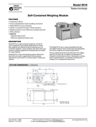
- 1. Tedea-Huntleigh www.vpgtransducers.com 1 Model 9010 Technical contact in Americas: lc.usa@vishaypg.com; Europe: lc.eur@vishaypg.com; Asia: lc.asia@vishaypg.com Document No.: 12062 Revision: 31-Jul-2012 Self-Contained Weighing Module FEATURES • Capacities 3–90 kg • Unique adjustable tare load cancelling mechanism • Highly effective viscous damping • 6 Built-in overload limit stops in three directions • Weighing speed is much faster than standard load cell • IP65 protection • Optional ❍❍ Stainless steel version ❍❍ IP66 with additional breather tube DESCRIPTION Model 9010 is a self-contained weighing module for use in repeated shock-loading applications or where fast weighing and settling times are required such as multihead weighers, check weighers and other static and dynamic weighing applications characterized by sudden or impact loading. Model 9010’s unique fluid damping system allows the load cell to be used in applications that previously required the use of LVDT’s or similar types of measuring devices. The Model 9010 has a unique adjustable tare load cancellation feature which brings load cell adaptability into check weighing and grading applications. The two additional sense wires feed back the voltage reaching the load cell. Complete compensation of changes in lead resistance due to temperature change and/or cable extension, is achieved by feeding this voltage into the appropriate electronics. OUTLINE DIMENSIONS in millimeters Protected under U.S. Patent No: 5,232,062 Outline Dimensions All Capacities 115.6 10.0 97.3 199.5 92.0 19.05 71.5119.8 46.0 19.05 82.0 4 Mounting Holes Ø 7.04 x Load Mounting Holes ¼-20UNC or M6 x 14mm Deep Self-Contained Weighing Module Document No.: 12062 Revision: 31-Jul-2012 Model 9010
- 2. Tedea-Huntleigh www.vpgtransducers.com 2 Model 9010 Technical contact in Americas: lc.usa@vishaypg.com; Europe: lc.eur@vishaypg.com; Asia: lc.asia@vishaypg.com Document No.: 12062 Revision: 31-Jul-2012 Self-Contained Weighing Module HIGH PERFORMANCE DYNAMIC WEIGHING Weigh Module 9010 consists of a Tedea-Huntleigh single- point load cell enclosed in an environmentally protected, electroless nickel-plated aluminum housing. The Module integrates load cell performance, viscous damping, adjustable tare offset mechanism and overload protection. LOAD CELL Tedea-Huntleigh’s Model 1010, 1040 or 1140 single- point load cells can be used in the Model 9010. Standard capacities 3 kg to 90 kg; for higher capacities, consult Tedea-Huntleigh. OVERLOAD PROTECTION Model 9010 is equipped with built-in overload stops for positive (push), negative (pull) and twisting loads. These stops are factory adjusted for each specific application. DAMPING Model 9010 features a unique viscous damping technique developed and patented by Tedea-Huntleigh, which provides: • Faster settling time • Higher weighing speeds • Load cell protection (extended working life) Damping parameters are factory set for each specific application. TARE LOAD CANCELLING Model 9010 features an adjustable tare load cancelling mechanism which provides a tare offset of up to 35 kg (in several ranges). The tare offset is factory set but may be adjusted by the user. This feature enables the use of a lower capacity load cell, resulting in electronic circuits with lower gains, lower noise, higher stability and lower temperature drifts. An example for the power of tare cancelling: Assume an application with 5 kg dead load and 2 kg (useful) load. 1. Without tare cancelling: Total load of 5+2 is 7 kg, therefore, a load cell with capacity of at least 10 kg has to be selected. 2. With tare cancelling: The 5 kg dead load can be opposed and effectively cancelled by the Tare Cancellation Mechanism, leaving a load of 2 kg only, hence a capacity of 3 kg can be selected. 3. Results: A capacity of 3 kg rather than of 10 kg is enabled by the Tare Cancellation feature for a gain of over 3 times in resolution and noise. LOAD CELL LIFE Because of the design and unique features of Model 9010, the life of the load cell is increased substantially. For example, in one typical set of life tests, the undamped load cell failed after approximately 300,000 cycles. The damped load cell held without any significant deterioration for more than 300 million cycles. In this test a Model 1010 10-kg load cell was used. A dead load of 2.5 kg was mounted 150 mm from the mounting center. A 4.5 kg impact was applied at that point at a rate of 8 times/sec. ENVIRONMENTAL PROTECTION The load cell in the Model 9010 is completely enclosed in a rugged, electroless nickel-plated aluminium or stainless steel housing to withstand splashing. It is environmentally protected to IP65, a special “breather valve” allows atmospheric pressure equalization while excluding splashing liquids. With an optional addition of a breather tube the protection is rendered IP66. A built-in shut-off valve is used for shipping. SETTLING TIME Settling time is the elapsed time from the instant of loading to the time the load cell’s signal remains within the user specified accuracy. Settling time is affected by the following parameters. 1. Total mass on the module and it’s distance from the mounting center 2. Impact loading characteristics 3. Environmental temperature change For optimum performance, the above parameters must be specified by the user for each order.
- 3. Tedea-Huntleigh www.vpgtransducers.com 3 Model 9010 Technical contact in Americas: lc.usa@vishaypg.com; Europe: lc.eur@vishaypg.com; Asia: lc.asia@vishaypg.com Document No.: 12062 Revision: 31-Jul-2012 Self-Contained Weighing Module D CofG CofG F MOTOR A B C HOPPER CHECK WEIGHER ~ APPLICATION AND ORDER DATA TO BE COMPLETED BY THE CUSTOMER CUSTOMER’S NAME ......................................................................................................................... ORDER No. .................................... CONTACT PERSON ........................................................................................................................... DATE .............................................. APPLICATION ..................................................................................................................................... No. of UNITS .................................. TOTAL TARE WEIGHT (DEAD LOAD)..........................................................kg; FOR EACH UNIT......................................................kg TOTAL USEFUL WEIGHT (LIVE LOAD) .......................................................kg; FOR EACH UNIT......................................................kg DESCRIBE LIVE LOAD (POWDER, FRUIT, SCREWS ETC) ...................................................................................................................... REQUIRED SETTLING TIME ...............................................msec; ACCURACY..................................................................................... OPERATING TEMPERATURE RANGE °C: ...................................... MOUNTING THREADS .....................................................mm (6x1) ................................................ ................................inch (1/4 UNC) PREFERRED LOAD CELL, IF ANY.............................................................................................................................................................. 1. CHECK WEIGHER (SEE SKETCH BELOW):........................................................................................................................................... SIZE OF CONVEYOR PLATFORM: ............................................................................................................................................................. WIDTH........................................... cm; A ........................................ cm; B .....................................cm; C...........................................cm SPEED OF BELT ........................... cm/sec; SIZE OF WEIGHED PRODUCT IN MOVEMENT DIRECTION.......................................cm TARE WEIGHT DISTRIBUTION: CONVEYOR: ...................................... kg; MOTOR:........................................................................kg 2. HOPPER OR OTHER APPLICATION (SEE SKETCH BELOW): ............................................................................................................. CENTER OF GRAVITY (CofG) OF DEAD LO AD, (ESTIMATE IF NECESSARY): D..........................cm; F .....................................cm LOADING POSITION: D .........................cm; F ..................................... cm; DROP HEIGHT:.....................................................cm IF LOAD CofG VARIES, MAX DIST. BETWEEN EXTREMES ............................................................................... ................................cm SPECIAL REQUIREMENTS CABLE LENGTH IF NOT STANDARD (1 m) .............................................. ; DELIVERY REQUESTED ................................................... CORNERS ACCURACY: TEST WIGHT (MAX. ALLOWED 1/3 OF LOAD CELL CAPACITY) ............................................................kg DISTANCE FROM CENTER ................................................cm VARIATION ALLOWED ................................................................. DEFINITION OF LOADING POSITION RELATIVE TO 9010
- 4. Tedea-Huntleigh www.vpgtransducers.com 4 Model 9010 Technical contact in Americas: lc.usa@vishaypg.com; Europe: lc.eur@vishaypg.com; Asia: lc.asia@vishaypg.com Document No.: 12062 Revision: 31-Jul-2012 Self-Contained Weighing Module SPECIFICATIONS PARAMETER VALUE UNIT Rated capacity—R.C. 3, 5, 7, 10, 15, 20, 30, 50, 90 kg TH accuracy class G Maximum no. of intervals (n) 3000 Rated output—R.O. 2.0 mV/V Rated output tolerance 0.2 ± mV/V Total error* 0.030 ±% of R.O. Temperature effect on span* 0.002 ±% of R.O./°C Temperature effect on zero: load cell 0.004 ±% of load/°C Temperature effect on zero: buoyancy 0.15 +gr/°C rise Temperature effect on zero: tare offset 0.25 x tare offset (kg) +gr/°C rise Temperature range - standard* 10 to 30 °C Tare offset ranges 0 to 35 kg Safe static overload downward at mounting center upward at mounting center 200 mm in front or side of mounting center 800 400 200 % of R.C. % of R.C. % of R.C. Settling time—typical 40–300 millisecond Temperature effect on settling time 2 %/°C Excitation, recommended 10 VDC or VAC RMS Excitation, maximum 15 VDC or VAC RMS Input impedance 415±15 Ω Output impedance 350±5 Ω Insulation resistance >5000 MΩ Weight 3 kg Construction Anodized body, electroless nickel plating** Environmental protection IP65*** * Extended temperature ranges and smaller temperature effects are available upon request. ** Optional stainless steel coating available upon request. *** IP66 available with additional breather tube. All specifications subject to change without notice. Wiring Schematic Diagram +ve Input (Green) –ve Input (Black) +ve Sense (Blue) +ve Output (Red) –ve Output (White) –ve Sense (Brown)
- 5. Vishay Precision Group Document No.: 63999 Revision: 27-Apr-2011 www.vishaypg.com 1 Legal Disclaimer Notice Disclaimer Legal Disclaimer Notice Disclaimer Document No.: 63999 Revision: 27-Apr-2011 ALL PRODUCTS, PRODUCT SPECIFICATIONS AND DATA ARE SUBJECT TO CHANGE WITHOUT NOTICE. Vishay Precision Group, Inc., its affiliates, agents, and employees, and all persons acting on its or their behalf (collectively, “Vishay Precision Group”), disclaim any and all liability for any errors, inaccuracies or incompleteness contained herein or in any other disclosure relating to any product. The product specifications do not expand or otherwise modify Vishay Precision Group’s terms and conditions of purchase, including but not limited to, the warranty expressed therein. Vishay Precision Group makes no warranty, representation or guarantee other than as set forth in the terms and conditions of purchase. To the maximum extent permitted by applicable law, Vishay Precision Group disclaims (i) any and all liability arising out of the application or use of any product, (ii) any and all liability, including without limitation special, consequential or incidental damages, and (iii) any and all implied warranties, including warranties of fitness for particular purpose, non-infringement and merchantability. Information provided in datasheets and/or specifications may vary from actual results in different applications and performance may vary over time. Statements regarding the suitability of products for certain types of applications are based on Vishay Precision Group’s knowledge of typical requirements that are often placed on Vishay Precision Group products. It is the customer’s responsibility to validate that a particular product with the properties described in the product specification is suitable for use in a particular application. No license, express, implied, or otherwise, to any intellectual property rights is granted by this document, or by any conduct of Vishay Precision Group. The products shown herein are not designed for use in life-saving or life-sustaining applications unless otherwise expressly indicated. Customers using or selling Vishay Precision Group products not expressly indicated for use in such applications do so entirely at their own risk and agree to fully indemnify Vishay Precision Group for any damages arising or resulting from such use or sale. Please contact authorized Vishay Precision Group personnel to obtain written terms and conditions regarding products designed for such applications. Product names and markings noted herein may be trademarks of their respective owners.